R E S E A R C H
Open Access
TCP-based window-size delegation method for
TXOP Exchange in wireless local area networks
Takayuki Nishio
1*, Ryoichi Shinkuma
1, Tatsuro Takahashi
1and Go Hasegawa
2Abstract
We propose a TCP window-size delegation method for downlink TXOP (transmission opportunity) Exchange in wireless local area networks (WLANs). In our method, the‘compliant’stations (STAs) cooperatively use their available bandwidth in accordance with their throughput demand. We realize our method only with minimal modifications of the TCP functions of a proxy server, which lets one station (the TXOP provider) delegate TCP window size to another station (the TXOP client) so that the provider delegates its TXOPs in WLANs to the client. Our method enables an STA to flexibly delegate TXOPs to another STA without adversely affecting the legacy STAs, which is confirmed by computer simulations. We also confirmed that our method requires no modification to legacy access points and STAs.
Keywords:Bandwidth delegation, TCP window size, TXOP Exchange, Wireless local area networks
1 Introduction
In offices, homes, and public spaces, IEEE 802.11 wire-less local area networks (WLANs) has been extensively used to provide wireless Internet connection services. In WLANs, stations (STAs) connected to an access point (AP) compete for transmission opportunities (TXOPs) using the carrier sense multiple access with collision avoidance (CSMA/CA). TXOPs are almost equally assigned to the STAs and the AP without considering each STA’s throughput demand, especially when the traffic load is heavy. Although many quality of service (QoS) control mechanisms applicable for WLANs have been proposed including IEEE 802.11e, IntServ and Diff-Serv [1-3], they are not widely used basically because they require ‘physical replacement’ of existing APs or edge routers.
To solve this problem, we proposed TXOP Exchange [4-6]. In WLANs, the number of TXOPs obtained by each STA determines the throughput of the STA. Therefore, for the uplink, we modified only the STA-side media access control (MAC) protocol so that the STAs participating in TXOP Exchange (compliant STAs) can directly delegate TXOPs without affecting the performances of the other STAs. In TXOP
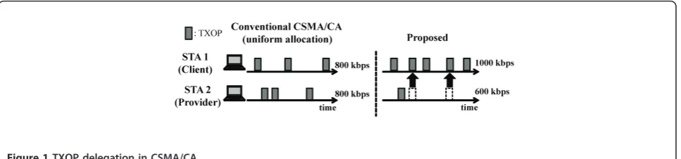
Exchange, compliant STAs cooperatively use their avail-able bandwidth in accordance with their required throughputs. Consider an example of a wireless access network with one AP, two STAs compliant with our architecture, and other STAs. Each of the STAs is downloading a large file, like a video file or a zipped file of photos, to a storage server. The throughput of the STAs is saturated at 800 Kbps. Suppose that one of the compliant STAs, STA 1, wants to increase its through-put to 1 Mbps to download its file faster. If the other compliant STA, STA 2, is not interested in downloading its file faster, then, as shown in Figure 1, it can delegate some of its TXOPs to STA 1 so that the throughput of STA 1 increases up to 1 Mbps. Throughput increase is always beneficial for STAs regardless of how much it is particularly when they download files or receive audio/ video streams with progressive download. In this exam-ple, STAs 1 and 2 are a TXOP client and a TXOP pro-vider, respectively. Each compliant STA can become a provider or a client as necessary. Thus, cooperative exchange of TXOPs enables STAs to satisfy the throughput requirements each other. TXOP Exchange enables compliant STAs to flexibly exchange bandwidth without modifications on the legacy APs and without affecting the performances of the other“non-compliant” STAs, as illustrated in Figure 2.
* Correspondence: [email protected]
1Graduate School of Informatics, Kyoto University, Kyoto, Japan Full list of author information is available at the end of the article
We previously focused on the use of TXOP Exchange for the uplink [4,5]. In this paper, we focus on extending TXOP Exchange so that it can be used for the downlink as well. Unlike the uplink, we cannot realize TXOP Exchange for downlink only by MAC-layer modification at STAs since the packets are sent to the STAs from the connecting AP by using the AP’s TXOP; in other words, the STAs share TXOPs of the AP for their downlink communications. On the other hand, AP sends a packet in the top of sending queue of the AP. Therefore, to enable an STA to delegate its TXOPs to another STA, we need to control the number of packets in the AP sending queue. Considering the implementation con-straint and cost, we propose a transport-level control method that uses proxy servers to control the number of packets arriving at the AP. A proxy server plays roles of a coordinator between STAs and a manager for TCP connections of compliant STAs. In this method, a TXOP provider delegates a chance to increase its TCP window size to the TXOP client, which is controlled by the proxy server. The proxy server also decreases the window size for the TXOP provider where as that for the TXOP client would be decreased with the legacy TCP. This method does not require any modifications of the APs or the legacy STAs and is applicable to access networks other than WLANs since it is based on end-to-end TCP-level controls.
The rest of this paper is organized as follows. Section 2 briefly introduces our TXOP delegation method for the uplink and show how it works. In Section 3, we describe out TXOP delegation method for the downlink in detail. In Section 4, we observe how our method works through computer simulations and verify that it enables an STA to delegate throughput to another STA, while the other STAs see the same throughput as before. We also discuss the performance with varying the number of other STAs and round trip time (RTT). Finally, we mention the related work and conclude our paper in Sections 5 and 6.
2 Previous work: TXOP Exchange for uplink CSMA/CA, which is deployed in WLANs, was originally designed for assigning TXOPs equally to the STAs when the traffic load is heavy. An STA is able to send a data frame when it obtains a TXOP. In WLANs, to the best of our knowledge, there has been no method that enables an STA to delegate its TXOPs to another STA without modification to APs. Therefore, we newly designed a TXOP delegation method in WLAN in [4]. The proposed method requires small modification to the conventional IEEE 802.11 mechanism only of com-pliant STAs and it does not affect co-existing legacy STAs’behaviors. The proposed method exploits RTS/ CTS mechanism to provide such characteristics.
In CSMA/CA with RTS/CTS, an STA sends an RTS frame to the AP before sending a data frame, and the AP sends a CTS frame back to the STA to allocate a TXOP to it and to prohibit the other STAs from send-ing any frames dursend-ing the network allocation vector (NAV) period. Since the RTS frame includes the sender address field, the AP can recognize which STA sent it. In our TXOP Exchange for uplink, the TXOP provider replaces the source address field in the RTS frame with the client address to force the AP to allocate a TXOP to the client with the corresponding CTS frame. We call this RTS frame the coop RTS frame. The provider cal-culates the NAV duration based on the data frame size and the physical transmission rate of the client and includes it in the coop RTS frame. We also introduce a
Proposed Conventional CSMA/CA
(uniform allocation)
STA 2 (Provider)
STA 1 (Client)
: TXOP
time time
800 kbps
800 kbps 600 kbps 1000 kbps
Figure 1TXOP delegation in CSMA/CA.
A B C
A C
Delegated bandwidth Bandwidth
Bandwidth B
STA A
(Client) (Provider)STA B (Other)STA C
coordination server, which a proxy server plays a role of as mentioned in Section 1, to handle the client’s infor-mations, such as MAC and IP address, physical trans-mission rate, data frame size, and throughput requirement. As discussed in our prior work [6], the coordination server works to ensure fairness between STAs and stimulate them to cooperate each other. We also proposed an algorithm that determines how fre-quently the coop RTS frames are sent from the provider according to the required throughput of the client [4,5].
We implemented this method in the QualNet 4.5 [7] simulator. Figure 3 shows the average throughput of each STA as a function of No, where is a single-AP
net-work with a provider, client, and No other STAs. We
assume that the client is requesting additional 500 Kbps throughput from the current throughput. This figure shows that the provider can provide 500 Kbps from its throughput to the client. For example, when the number of other STAs was twelve, the throughput before TXOP delegation (conventional in the figure) was 1.05 Mbps, while the throughputs for the provider and the client after delegation were 0.61 and 1.53 Mbps. We should note that the other STAs in our method behaved the same as in the ‘conventional’, which indicate the throughput when STAs do not exchange TXOPs.
3 TXOP Exchange for downlink
In the downlink of WLANs, the throughput for each STA connected to the AP depends on the number of packets for each STA in the AP sending queue, because the AP sends the packet at the top in its sending queue when it obtains a TXOP. We here consider an example of a wireless access network with one AP and three STAs, STA A, STA B, and STA C. If the ratio of the
number of packets for STA A, B and C in the sending queue of AP is a, b, andc, the downlink throughputs of the STAs are θA =a·θtotal,θB =b · θtotal, and θC =c ·
θtotal
, respectively, where θtotalis the total throughput of STAs. Therefore, for instance, if we want to assign a portion of the bandwidth for STA B to STA A without affecting STA C as illustrated in Figure 2, a and b
should be increased and decreased, respectively, while maintaining c constant. Therefore, we enable the throughput delegation by controlling the number of packets for each STA in the AP sending queue.
There are a couple of possible ways of controlling the ratio of the number of packets for STAs in the AP send-ing queue. One solution may be to replace every AP by the ones equipped with a new queueing function, which is a counter direction of our goal. We therefore chose a transport-level approach. Assigning multiple TCP flows to an STA can be another solution to increase through-put for the specific STA. However, as we will show a simulation example in Figure 4, it is impossible to con-trol throughputs without affecting other STAs. There-fore, we consider modifying the transport protocol in this paper. Since it is unrealistic to modify the transport protocol for every server, we assume that proxy servers are located in each autonomous system (AS) network between the STAs and corresponding servers from which STAs are originally downloading data. The detail of our approach is described in the next subsection.
3.1 System model
Figure 5 illustrates the system model of our TXOP Exchange for the downlink. A proxy server is located in each AS network, while our compliant STAs maintain sessions with the proxy server and download data from
0 1 2 3 4 5 6
1 3 5 7 9 11 13 15 17 19
Th ro ug hp ut (M bp s)
No. of other o
Client Provider Others Conventional
the corresponding servers via the proxy server. Here, we consider an example of window-size delegation between a pair of a provider and a client, both of which connect to an AP. Since the number of packets sent by a server to an STA in RTT is approximately the same as the window size of a TCP flow for the STA [8], the proxy server changes the provider’s and client’s window sizes while keeping the total size unchanged so as to control the ratio of the numbers of their packets arriving at the AP but keeping the number of packets for other STAs unchanged. The proxy server manages TCP flows for the two STAs to enable the provider to delegate its TCP window size to the client. Since TCP flows from the corresponding servers are terminated at the proxy ser-ver, what we need to discuss is only the behaviors of TCP flows from the proxy server to the STAs.
3.2 Basic mechanism of TCP window-size delegation Figure 6 represents an example of behaviors of TCP window sizes for a provider, a client, and a non-compli-ant STA when our window-size delegation works ideally. When the proxy server has received a normal ACK packet, which differs from triple-duplicate ACKs, from the provider, in other words, when the flow for the
provider is in the congestion-avoidance phase, the proxy server increases either of the window sizes for the client
Wcor for the providerWpas below:
Wp=Wp+p(with prob.1 -α)
Wc=Wc+p(with prob.α)
(1)
where Δp was set equal to 1/Wp as in the
conven-tional TCP. It should bonoted that, when the proxy ser-ver has received a normal ACK packet from the client, just as in the conventional TCP, the proxy server updates the client’s window size as Wc = Wc + Δc,
whereΔc= 1/Wc.
The algorithm in Equation 1 means that asaincreases, more window size is delegated from the provider to the client. When the flow for the client is in the slow-start phase and when the flow for the provider is in conges-tion-avoidance phase, the increase in the window size is kept held until the flow for the client comes back in the congestion-avoidance phase and then will be added to the client’s window size. In addition, the proxy server records and updates a virtual window sizes of the provi-der and client, Wv
p andWcv, respectively, which they would obtain if the provider did not delegate its window size to the client. The virtual window size,Wv
x(x=corp), 0
1 2 3 4 5 6 7
1 2 3 4 5
T hr ou gh pu t ( M bp s)
umber of flow for STA A
STA A STA B STA C
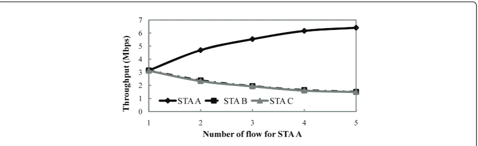
Figure 4Throughputs for STAs A, B, and C versus the number of flows assigned to STA A. We used the model in Figure 9.
Compliant STAs
AS
AP
Corresponding
Server
(CS 1)
CS 2
Proxy
Server
is updated by Wv
x=Wxv+ 1/Wxv when Wxv>0 and
Wv
x=Wx+ 1/WxwhenWxv= 0.Wxvis updated only when the proxy server receives an ACK packet from the STA x. Although the above procedure enables a client to increase its window size, its throughput does not neces-sarily increase because the larger window size of a TCP connection may increase a loss ratio of data packets it sends. Therefore, when the proxy server receives triple-duplicate ACKs from a client, it decreases the provider’s and client’s window size as below:
Wp=Thssp =Wpv/2 (with prob. β)
Wc=Thssc =Wcv/2 (with prob. 1−β),
(2)
whereThssp andThssc are the slow-start threshold of the flow for the provider and client, respectively. Equation 2 means that, as b increases, Wc decreases less often,
which implies the client’s window size is maintained lar-ger. It should be noted that the proxy server retransmits the packets corresponding to the duplicate ACKs in
both cases in Equation 2. After decreasing the window size of the client/provider, the virtual window size of the client/provider is initialized by 0.
3.3 How to setaandb
Figure 7 shows the state diagram of our window-size delegation method. In our method, first of all, a proxy server is required to set a and b in accordance with required throughput and other referenced parameters. Then, it starts the window-size delegation. In this sec-tion, we discuss how to setaandb.
3.3.1a
Here, we consider a case where STA ibecomes a client, STAjbecomes a provider, respectively. We set optimal
ain accordance with a required throughput of STAiθir
and a‘referenced’throughput of the STA θi. As the first
step just after the‘start’in Figure 7, a proxy server mea-suresθi before starting the window-size delegation, and
then the proxy server calculates appropriate afrom θi
andθir.
co ng es tio n
w in do w si ze
time
ProviderClient Other STAs
Figure 6Ideal change in congestion window size over time whena= 1.0.
Measure θiand i
Set α (Start)
Start window size delegation Wait for ACKs
β adjusting algorithm Decrease Wpto Wpv/2
Decrease Wcto Wcv/2
Resend packet 1 2
β> rand
Decrease Wpto Wpv/2
Resend packet
Increase Wc Increase Wcv Send packets
Set Wpv= Wpv/2
Set Wcv= Wcv/2
True
False α> rand
Increase Wc
Increase Wpv
Increase Wp
Send packets
False True
3 4
1 2 3 4
: Recv an ACK from provider : Recv duplicate ACKs from provider
: Recv duplicate ACKs from client : Recv an ACK from client
Start window size delegation with β= 0 Measure p0and c0
Set β
Procedure for Setting β Procedure for Setting α
Let us show the relationship between throughput and window size without window-size delegation. Ideally, in the steady state, the congestion window size of STA i Wi(t) changes as the dashed line does in Figure 8. In
this case, the relationship is written as
θi= (Di) the congestion window size when triple-duplicate ACKs occur in the steady state;TDiis a duration after
triple-duplicate ACKs occur until the next triple-triple-duplicate ACKs occur.
When STA i becomes a client, if our method works ideally, the congestion window size of STA i Wci(x)
changes as the gray line does in Figure 8. Here, the throughput of STAiθciis written as
θci= (Di) dow-size delegation increases an increasing slope ofWci
(x) in an interval of linear to (1 +a)-fold fromWi(x). If
we want to control window-size delegation so thatθci
equals toθir, from Equation 4,ashould be set as times triple-duplicate ACKs for a client and a provider, respectively, occur while the window-size delegation is operated witha given in Section 3.3.1 andb= 0. After setting a, a proxy server starts window-size delegation with the aandb= 0 and then measuresN0ciandN0
pj, as illustrated in Figure 7. Then, b is set using measured parameters,Nci0and N0pj.
How many times the proxy server decreases the win-dow sizes for the client and the provider,NcidNdpj, can be
approximated by Nd
ci= (1−β)N0ci and
Nd
pj=Npj0+β·Nci0, respectively. The effect on the other STAs is minimized when Nd
ci=Ndpjbecause the total of the decreased window size caused by triple-duplicate ACKs for the provider and the client is almost twice as that for the other non-compliant STA. Therefore, b should be set to(N0
ci−N0pj)/2N0ci.
3.4 Adjusting algorithm forb
We discussed how to setb in Section 3.3.2. However, even using the determined b, window-size delegation slightly affects throughputs of other STAs because of a difference ofNci, which is how many times
triple-dupli-cate ACKs occur in a certain period, fromN0
ci, which is initially measured. Here, if the probability that packet loss occurs is the same for all STAs in the network, the following relationship is obtained from Equation 4, which represents the relationship between the actual and referenced throughput of the client:
Nci= 3 +α
3 Ni, (7)
whereNiis the referenced number of how many times
triple-duplicate ACKs occur in Figure 7. Assuming that
Client Without TXOP Exchange
co
our window-size delegation method works ideally, if a provider delegates its window size to a client without affecting on others’throughputs, Equation 7 should be satisfied.
Based on the above discussion, we come up with b adjustment algorithm that adjustsb to maintain Equa-tion 7 satisfied. A simple algorithm for this is
β=β+u
ifNci< 3 +α
3 Ni
β=β−d
ifNci> 3 +α
3 Ni
The proxy server adjusts b based on the algorithm every time duplicate ACKs are received from for STAi, which is illustrated in Figure 7. We setΔu =Δd= 1 in the following simulation section to let Nciconverge to
Ni(3 +a)/3 fast.
4 Simulation evaluation 4.1 Simulation setup
We evaluate our delegation method using QualNet simula-tor [7]. We assume a network in which a provider and a cli-ent download data using TCP from a corresponding server, while the other STA download data directly from another corresponding server. Each of the STAs used only one flow. We assume that a bandwidth between the proxy ser-ver and the corresponding serser-ver for the provider and the client is large enough not to limit throughputs for them. We also idealize wireless channels to make our discussion simple. For instance, when an STA with lower channel quality delegates its TXOPs to another STA with higher channel quality, the overall transmission efficiency might improve. This issue should be included in future work.
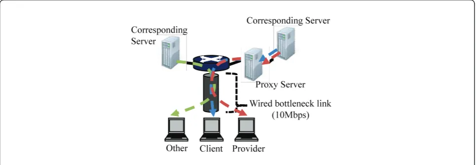
In Section 4.2, we will first observe the dependence of throughputs on a and bof our method introduced in Section 3.2. To observe the basic characteristics of the proposed method, we used the network model illu-strated in Figure 9, where the wireless link is modeled as simply a wired 10 Mbps bottlenecklink; since every packet in a WLAN downlink is always sent from the AP, results from this model would not be far from the ones from a model with CSMA/CA. Therefore, here, the maximum total amount of throughputs of STAs is lim-ited to 10 Mbps by this bottlenecklink.
However, in Section 4.3, we will evaluate the effective-ness and the scalability of our method with a wireless network in a WLAN access link is the bottleneck as illu-strated in Figure 10. The parameters regarding the wire-less link completely follow the standard of IEEE 802.11a, though we fixed the transmission rates to 24 Mbps with no channel errors. In this model, because of the MAC overhead, the total amount of throughputs of STAs is limited to approximately 13.5 Mbps when there are three STAs.
4.2 Dependence of throughputs onaandb
We first demonstrate how a conventional method works. As mentioned in Section 3, a simple way to increase throughput of an STA is to assign multiple flows for the STA. Figure 4 shows the throughputs of each STA as a function of the number of flows assigned to STA A. With increase the number of flows for STA A, the throughput for STA A increases, while through-puts for STAs B and C decrease. As shown in this example, the conventional method may differentiate throughputs but it affects the non-compliant STAs significantly.
Other Client Provider
Wired bottleneck link (10Mbps) Proxy Server Corresponding Server Corresponding
Server
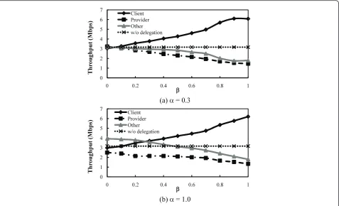
We next observe how our window-size delegation work with varying givenaand b, which means, here, we did not use our criteria for determining a and b described in Sections 3.3. Figures 11a, b plots the throughput of each STA as a function ofb fora= 0.3 and 1.0, respectively.‘w/o delegation’means the average
throughputs for STAs when our method is not used. As you first see in these figures, we successfully increased the throughput for the client compared with‘w/o dele-gation’ by the delegation from the provider. We also observe the increased and decreased throughputs for the client and the provider increase, as givenb increases.
Proxy Server
Wireless bottleneck link (Phy. trans. rate: 24 Mbps) RTTo RTTP
Corresponding Server
Corresponding Server
Other Client Provider
Figure 10Simulation model of WLAN. We used QualNet 4.5.1; TCP SACK with delay-ACKs, Nagale algorithm, RFC1323, and Keepalive probes; maximum segment size was 1,500, bytes; send buffer size was 65,000 bytes; receive buffer size was 65,000, bytes; Access network is IEEE 802.11a WLAN with physical transmission rate of 24 Mbps; other links’bandwidth were 100 Mbps;RTTPwas 10 ms whileRTTovaried from 10 to 500 ms.
(a) α = 0.3
(b) α = 1.0
0 1 2 3 4 5 6 7
0 0.2 0.4 0.6 0.8 1
T hr ou gh pu t ( M bp s)
β Client
Provider Other w/o delegation 0
1 2 3 4 5 6 7
0 0.2 0.4 0.6 0.8 1
T hr ou gh pu t ( M bp s)
β Client
Provider Other w/o delegation
However, the throughput for the other STA is not kept equal to the one in ‘w/o delegation’and depends on a andb. We see the intersection of the throughput for the other between with and without delegation at a combi-nation ofa andb, which suggests we have to choosea andbappropriately.
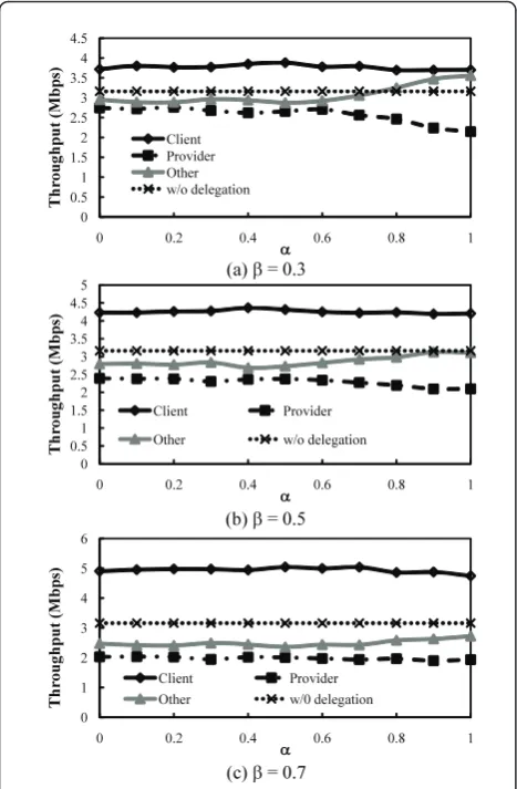
Figures 12a, b, c show the throughput of each STA as a function of a for b = 0.3, 0.5, and 1.0, respec-tively. We can observe from these figure that the throughput of the client remains almost unchanged and independent of a. However, the throughput for the other STA increased when a exceeded a certain point. Unless b is 0.7, when a was appropriately set, the throughput for the other STA was the same as w/o delegation.
The above results suggest we have to introduce an adaptive algorithm for determininga and b appropri-ately. Now, we start to use our designed algorithm
described in Section 3.3. Figure 13 plots the result as a function ofΔr, which is the required additional
through-put from the client: how much the client wants to increase its throughput than before starting TXOP Exchange. We see in the figure that the throughput of the client is successfully controlled almost equally toΔr
without affecting that of the other STA.
4.3 Performance of window-size delegation method in WLANs
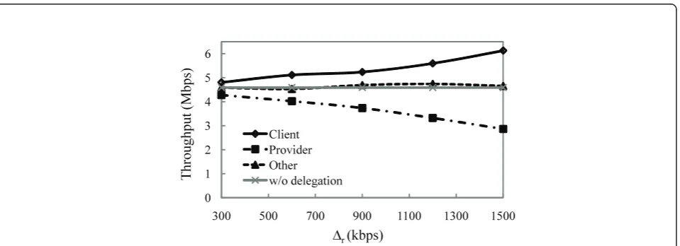
We here evaluate the performance of our method with using a wireless network in Figure 10. Figure 14 shows the average throughput of each STA as a function ofΔr.
In this figure, we confirm the throughput for the client is increased almost equally to Δrcompared with ‘w/o
delegation’ without affecting the throughput for the other STA.
Next, we evaluate the scalability of our method through the following two scenarios, in which the same simulation parameters are used as in Figure 11 except the number of STAs and RTTs between corresponding servers and the AP.
First, we investigate a case where the number of other STAs varies. We assume a network with a provider, a client, and Noother STAs. RTTs here were identically
set to 10 ms. Figure 15 plots the average throughput of each STA as a function of No, in which‘w/o delegation
(compliant)’ indicates the throughput of compliant STAs which download data from the proxy server with-out the window-size delegation, while ‘w/o delegation (other)’indicates the throughput of other STAs which download data from their corresponding server without the window-size delegation. We fixed the required throughput Δr to 300 Kbps. As seen in the figure,
regardless ofNo, the client keeps its increased
through-put approximately 300 Kbps larger than that in ‘w/o delegation (compliant)’. We also see the throughputs of the other STAs did not change from ‘w/o delegation (others)’.
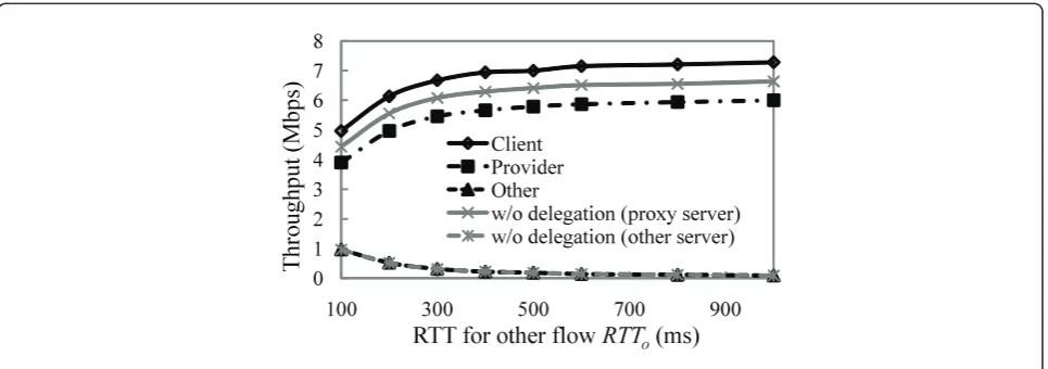
Second, we investigate a case where RTT between the corresponding server for other STAs and the AP RTTo
is different from RTT between the proxy server and the APRTTP . Since the proxy server is located in the same
as the AP and the others’ corresponding server is located in somewhere in the Internet, RTTocan be a
lit-tle or much larger than RTTP . We assume thatRTTP
was 10 ms while RTTovaried from 100 to 500 ms. We
fixed the total number of STAs to 10, which consists of a provider, a client and eight other STAs. Figure 16 shows average throughputs of each STAs versus RTT of flows for others. We set the required throughput Δrto
600 Kbps. This figure also shows that the client main-tains its increased throughput approximately 600 Kbps larger than compared with ‘w/o delegation (compliant)’
(a) β = 0.3
Figure 12Throughput for each STA versusawhen ab= 0.3, b
while others’throughputs are not changed regardless of RTT. As in the above observations, our method enables the client to increase its throughput, which is always beneficial regardless of how much the increase is parti-cularly when they download files or receive audio/video streams with progressive download as described in Sec-tion 1.
5 Related work
Our window-size delegation method in Section 3 enables an STA to delegate its throughputs to another STA in accordance with the required throughput with-out any effect on other STAs. Our method requires only a proxy server which is compliant with our method. To the best of our knowledge, any conventional methods cannot do this. In this section, we introduce several con-ventional methods as below.
Many flow level QoS control methods have been pro-posed including IntServ and DiffServ architectures [2,3,9,10]. In [2,3,9], their approaches are basically to control bandwidths and/or delays of flows between edge routers. They can differentiate throughput and/or delays among flows, while they require replacements or modifi-cations on edge routers, which are limited to their appli-cation range. On the other hand, it has been discussed how to prioritize throughputs for specific STAs with only modifications on a server [10]. In [10], when a ser-ver receives duplicate ACKs from prioritized STAs, the server decreases congestion window size of flows for other altruistic STAs instead of the prioritized STA’s congestion window size. However, this method cannot ensure to increase a throughput of prioritized STA when the number of altruistic STAs is not satisfactorily large.
0 0.51 1.52 2.5 3 3.5 4 4.5
200 400 600 800 1000
Th ro ug hp ut (M bp s)
Δr (kbps)
Client Provider Other w/o delegation
Figure 13Throughput for each STA versusΔrwith one additional TCP flow other than client and provider (other).Δrindicates the
required additional throughput from the client. The model in Figure 9 was used.
0 1 2 3 4 5 6
300 500 700 900 1100 1300 1500
Th ro ug hp ut (M bp s)
Δr (kbps)
Client Provider Other w/o delegation
On the other hand, in WLANs, MAC level QoS con-trol methods also have been proposed including a QoS standard of WLANs called IEEE 802.11e [1]. The AP equipped with IEEE 802.11e can prioritize packets clas-sified as specific traffic like video and voice and differ-entiate throughputs for them from the other traffic. However, it does make it without giving some effect on other STAs in the network especially when the network includes non-compliant STAs. Cooperation methods have been also discussed [11,12] in WLANs. They dis-cussed cooperation in packet forwarding, which can be also effective but is a different model from ours. Furthermore, most of the conventional cooperation methods in wireless networks including [11] and [12] were discussed only in the link or/and physical layer.
6 Conclusion
We proposed a TCP window-size delegation method for downlink TXOP Exchange in WLANs. In our method, a proxy server lets one station (the TXOP provider) dele-gate TCP window size to another station (the TXOP cli-ent) so that the provider delegates its TXOPs in CSMA/ CA to the client. Our method enables an STA to flexibly delegate TXOPs to another STA without adversely affecting the legacy STAs, which is confirmed by com-puter simulations. We also confirmed that our method requires no modification to legacy APs and STAs and needs only minimal modifications of the TCP functions of the proxy server.
We would like to mention that our method enables
N-providers to delegate their window size toM-clients
0
0.5
1
1.5
2
2.5
3
3.5
4
4.5
5
1
3
5
7
9
11
Th ro ug hp ut (M bp s)
No. of other No
Client
Provider
Others
w/o delegation (compliant)
w/o delegation (others)
Figure 15Average throughput of each STA versusNoin network with provider, client, and otherNoSTAs. Bottlenecklink was IEEE 802.11a WLAN with physical transmission rate of 24 Mbps. RTTs between AP and corresponding servers were identically 10 ms.
0 1 2 3 4 5 6 7 8
100 300 500 700 900
Th
ro
ug
hp
ut
(M
bp
s)
RTT for other flow
RTT
o(ms)
Client Provider Other
w/o delegation (proxy server) w/o delegation (other server)
simultaneously, although, in this paper, we consider only a case where a provider delegates its window size to a client. We will observe the case where N-providers dele-gate their window size to M-clients in the future work. Future work also includes a design of a coordination algorithm that ensures fair incentives for cooperation between STAs.
Acknowledgements
This work is supported in part by the National Institute of Information and Communications Technology (NICT), Japan, under Early-concept Grants for Exploratory Research on New-generation Network.
Author details
1Graduate School of Informatics, Kyoto University, Kyoto, Japan2Cybermedia Center, Osaka University, Osaka, Japan
Competing interests
The authors declare that they have no competing interests. Received: 2 February 2011 Accepted: 11 August 2011 Published: 11 August 2011
References
1. IEEE Std 802.11e,Medium Access Control (MAC) Quality of Service Enhancement(Nov 2005)
2. R Braden, D Clark, S Shenker,Integrated Services in the Internet Architecture: An Overview, RFC 1633 (June 1994)
3. S Blake, D Black, M Carlson, E Davies, Z Wang, W Weiss,An Architecture for Differentiated Services, IETF RFC 2475 (Dec 1998)
4. T Nishio, R Shinkuma, T Takahashi, N Mandayam, TXOP Exchange: A Cooperative Resource Exchange Method in CSMA/CA, inIEICE General Conference, B-15-6 (March 2010)
5. T Nishio, R Shinkuma, T Takahashi, N Mandayam,Transmission-Opportunity Exchange for Cooperative Bandwith Allocation in Wireless Local Area Networks. IEICE Technical Report, MoMuC2010-3, 13–18 (May 2010)
6. T Nishio, R Shinkuma, T Takahashi, N Mandayam, A Coordination Algorithm for N-node Cooperation Problem in Open-Resource Wireless Access Networks, inIEICE Communications Society Conference, BS-9-5 (Sept 2010) 7. QualNet, http://www.qualnet.com
8. J Padhye, V Firoiu, D Towsley, J Kurose, Modeling TCP throughput: a simple model and its empirical validation, inProceedings of ACM SIGCOMM, 303–314 (Oct 1998)
9. M Guirguis, A Bestavros, I Matta, N Riga, G Diamant, Y Zhang, Providing soft bandwidth guarantees using elastic TCP-based tunnels, inInternational Symposium on Computers and Communications, Proceedings of ISCC 2004, 760–765 (July 2004)
10. J Valdez, M Guirguis, Liberating TCP: the free and the stunts, inInternational Conference on Networking, 2008, ICN 2008, 72–77 (Apr 2008)
11. P Liu, Z Tao, S Narayanan, T Korakis, S Panwar, CoopMAC: a cooperative MAC for wireless LAN. IEEE J Sel Areas Commun.25(2), 340–354 (2007) 12. P Bahl, R Chandra, P Lee, V Misra, J Padhye, D Rubenstein, Y Yu,
Opportunistic use of client repeaters to improve performance of WLANs. IEEE/ACM Trans Netw.17(4), 1160–1171 (2009)
doi:10.1186/1687-1499-2011-58
Cite this article as:Nishioet al.:TCP-based window-size delegation
method for TXOP Exchange in wireless local area networks.EURASIP
Journal on Wireless Communications and Networking20112011:58.
Submit your manuscript to a
journal and benefi t from:
7 Convenient online submission 7 Rigorous peer review
7 Immediate publication on acceptance 7 Open access: articles freely available online 7 High visibility within the fi eld
7 Retaining the copyright to your article