R E S E A R C H
Open Access
A survey of performance enhancement of
transmission control protocol (TCP) in wireless
ad
hoc
networks
Noor Mast
1,2*and Thomas J Owens
1Abstract
Transmission control protocol (TCP), which provides reliable end-to-end data delivery, performs well in traditional wired network environments, while in wirelessad hocnetworks, it does not perform well. Compared to wired networks, wirelessad hocnetworks have some specific characteristics such as node mobility and a shared medium. Owing to these specific characteristics of wirelessad hocnetworks, TCP faces particular problems with, for
example, route failure, channel contention and high bit error rates. These factors are responsible for the
performance degradation of TCP in wirelessad hocnetworks. The research community has produced a wide range of proposals to improve the performance of TCP in wirelessad hocnetworks. This article presents a survey of these proposals (approaches). A classification of TCP improvement proposals for wirelessad hocnetworks is presented, which makes it easy to compare the proposals falling under the same category. Tables which summarize the approaches for quick overview are provided. Possible directions for further improvements in this area are
suggested in the conclusions. The aim of the article is to enable the reader to quickly acquire an overview of the state of TCP in wirelessad hocnetworks.
1. Introduction
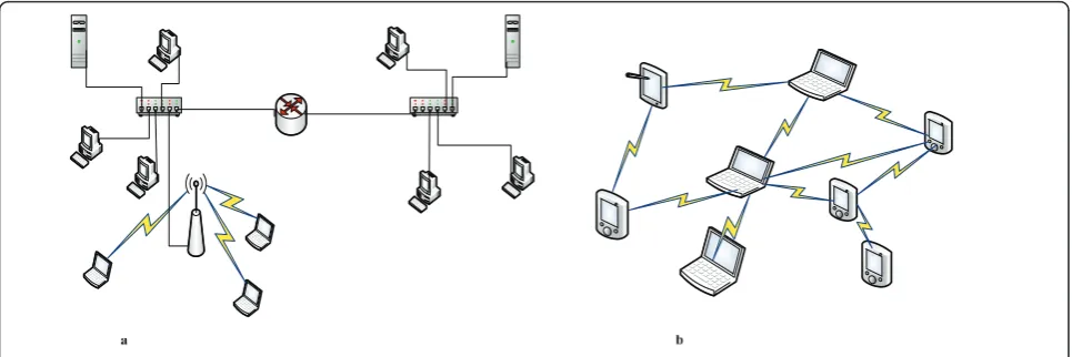
Over the last decade, there has been a very rapid growth in wireless technology. One of the aims of wireless tech-nology is to provide network availability to users every-where, at all times and at low cost. Fundamentally, wireless networks can be divided into two types: infra-structure, andad hocnetworks (also called infrastruc-ture less networks). Examples of infrastrucinfrastruc-ture and wireless ad hoc networks are given in Figure 1a, b, respectively. In an infrastructure network, the wireless nodes have access to a wired network through a wired access point (AP) which works as a backbone. A
wire-less ad hoc network is a collection of nodes, and its
characteristics can be summarized as follows [1,2]:
• Nodes communicate through wireless links using shared medium.
•A node can work as a router.
•There is no infrastructure and centralized control.
•Nodes can be static or free to move.
• Nodes can join or leave the network without any restriction.
•It can be setup anywhere.
Owing to their flexible structure, wireless ad hoc net-works are well suited for scenarios where an infrastruc-ture is unavailable. Thus, they can be used for crisis management services applications, such as in disaster relief operations where the quick restoration of commu-nications infrastructures is essential. Other examples of their use include police exercises, urgent business meet-ings outside the office environment and in battlefield applications by the military including situation aware-ness systems, where IEEE 802.11 MAC protocol [3] pro-vides support to establishad hoc networks. It is obvious that wirelessad hocnetworks have the potential to pro-vide significant facilities to users. However, owing to these specific characteristics of wireless ad hoc net-works, there are a lot of technical problems that need to be solved to achieve an efficient utilization of wireless technology. The research community is trying to solve these technical problems and formulate possible smooth deployment of wireless technology. Transmission con-trol protocol (TCP) [4], which is a dominant transport * Correspondence: [email protected]
1School of Engineering and Design, Brunel University, London, UK
Full list of author information is available at the end of the article
layer connection oriented and reliable end-to-end proto-col, is facing challenges in wireless ad hoc networks. From the literature review reported in this article, it is clear that TCP faces the following challenges in wireless
ad hocnetworks:
•Route failure and network partition
•Shared medium
○Hidden and exposed terminal problem
○Channel contention
•High bit error rate and burst losses
•Inability to differentiate congestion losses from other losses
The objectives of this article are to provide a clear overview of different proposals suggested by the research community for performance improvement of TCP in wirelessad hocnetworks and provide a guide as to what are the possible directions for further improve-ments in this area. In this way, it aims to provide an overview of the current state of TCP on wirelessad hoc networks. In the process, a classification of the proposals is provided to give the reader a new angle from which to view the work on TCP in wireless ad hocnetworks. Discussion in the article will show that this classification makes it easy to compare approaches that fall under the same category. It is difficult to present a comprehensive comparison of all the approaches together because each one addresses specific problems.
This article is organized as follows. Section 2 presents a brief overview of the working mechanism of TCP, while Section 3 outlines the challenges TCP faces in wirelessad hocnetworks. Section 4 presents a survey of the approaches available to improve the performance of TCP in wirelessad hoc networks and provides taxon-omy of these approaches. Section 5 concludes the article and provides suggestions for possible directions for
future study seeking to improve the performance of TCP in wirelessad hocnetworks.
2. TCP working mechanisms
TCP is a window-based reliable transport layer protocol that achieves its reliability through sequence numbers and acknowledgements (ACKs). TCP uses the ACK as a clock to transmit data to the network and adjust its transmission rate according to the available network capacity; because of this mechanism, TCP is also known as a self-clocking algorithm.
according to [5]. To identify segments damaged in tran-sit, the TCP sender adds a checksum field to each seg-ment, and the receiver must apply validate the checksum on receiving each segment, discarding the segment if the validation fails.
TCP also provides a mechanism for the receiver to control the amount of data a sender is sending to it. The receiver specifies in each ACK a window size (win-dow size means the amount of data) named the adver-tised window or receiver window (rwnd) that the receiver is ready to accept. Similarly, a congestion win-dow (cwnd) specifies the amount of data a sender can transmit to a receiver without receiving any ACK from the receiver for the data sent to it. The amount of data equal to the minimum of one of these windows will be transmitted over the network by the sender, i.e.
data to be transmitted = min(cwnd, rwnd).
Slow start and congestion avoidance are the two main phases of the TCP congestion algorithm. In the slow start phase the cwnd is incremented exponentially until the slow start threshold is reached. Afterward, the con-gestion avoidance phase starts, and the cwnd is incre-mented by one maximum segment size (MSS) up to some predefined value. In each phase, the cwnd is incre-mented in response to a non-duplicate ACK. It should be clear that TCP will recover one lost packet per round trip time (RTT). Thus, when multiple losses occur in the same cwnd, TCP may experience very poor performance. To overcome this problem, a selective acknowledgment (SACK) [6] was introduced. TCP New-Reno [7] provides an alternative way to tackle this pro-blem; the working mechanisms of SACK and TCP NewReno are explained below.
To understand the working mechanism of SACK, let us suppose that a TCP sender is sending data segments with sequence numbers in the following order where each segment consists of 512 bytes:
N= 500,N+ 512,N+ 1024,N+ 1536,N+ 2048,N+ 2560
Further suppose that the TCP receiver received two segments with sequence numbers ofN= 500 and N+ 2560, which means that the four segments having sequence numbers betweenN= 500 andN+ 2560 are missing. After receiving the segment N + 2560, the receiver will ask for the retransmission of the segment N+ 512 in ACK. Thus, the receiver confirms that it has received the segments with sequence numbers less than N + 512. Although the receiver has also received the segment of sequence numberN+ 2560, it does not pro-vide any information to the sender about this segment. In contrast, the SACK has an option that allows the TCP receiver to acknowledge that it has received non
contiguous data segments. Thus, in the case of a lost segment(s), the sender can infer from the SACK which segment(s) has(have) been lost and should be retrans-mitted. In the above example, the SACK can indicate that segments with sequence numbersN= 500 and N+ 2560 have been received. As a result, the sender will be able to infer that the segments between these two (i.e. segments of sequence numbers N+ 512,N+ 1024, N+ 1536 andN+ 2048) have been dropped.
On the other hand, it is stated in [7] that, in the absence of SACK, some information is still available to a TCP sender to detect a single or multiple segments lost and make a retransmission decision. To detect that there is a loss of a single or multiple segments, the first information available to the TCP sender comes from receiving an ACK for the retransmitted segment. If a single segment has been dropped, then the ACK received for the retransmitted segment must confirm the reception of all those segments transmitted before the activation of the TCP retransmission algorithm. If the ACK confirms some but not all of the segments, then it is an indication of multiple segments lost and the ACK is known as a partial ACK. In [7], it is sug-gested that the TCP sender respond to the partial ACK by inferring that the segments not acknowledged have been lost, and retransmit the first unacknowledged seg-ment. Thus, in response to each partial ACK, the TCP sender retransmits the next unacknowledged segment, until all the segments have been acknowledged. This modification to TCP Reno results in TCP NewReno.
3. Challenges for TCP in wireless ad hocnetworks TCP was designed for wired networks without consider-ing the complexity of wireless networks. With the advent of wireless technology TCP was also employed in wireless environments. In wireless technology, changes were made in the lower layers of the communications stack without considering their effects on the upper layers. Consequently, in wireless networks, the commu-nication environment is significantly different from that of wired networks, while TCP treats a wireless network like a wired one and, as a result, TCP faces challenges in wireless environments such as
I. Route failure and network partition
In wireless ad hoc networks nodes are free to remain static or move as well as can join or leave the network without any restriction. Owing to this freedom, wireless
ad hoc networks have a dynamic topology. As a result,
is computed, and the instantaneous throughput of TCP becomes zero. Therefore, frequent route failure means a lot of time is wasted in a network, just for searching new routes. During the path recovery process, there may be retransmission timeout (RTO) resulting in pack-ets’retransmission followed by an activation of the slow start algorithm of congestion control. In slow start phase, the cwnd size is set to one segment which is the minimum amount of data require to transmit over the TCP connection, which causes the poor utilization of the network resources. The second type of problem is network partition where the sender and receiver end up being located in separate networks as a result of route failure. Network partition can be more serious than sim-ple route failure if it remains unresolved for a long time, say longer than several RTO.
II. Shared medium
Owing to the shared medium, where the carrier sense multiple access with collision avoidance (CSMA/CA) method is used for medium access in the IEEE 802.11 MAC protocol [3], wireless networks have two main problems: (a) hidden and exposed terminals; and (b) channel contention.
(a) Hidden and exposed node problem
To explain the problem of hidden and exposed term-inals, the following example is provided:
Suppose there are four nodes A, B, C and D and adja-cent nodes are in transmission range of each other as shown in Figure 2. Both nodes B and C can communi-cate with two other nodes directly, while nodes A and D have only one node in direct communication range.
Further suppose that node A is transmitting data to node B while at the same time node C has started data transmission to node B. There will be data collision at node B because nodes A and C do not know about each other and are hidden from each other.
Now, suppose node B is sending data to node A and at the same time node C wants to transmit data to node D. When node C senses the medium, it finds that mission is taking place. Therefore, node C defers trans-mission, but actually there is no problem with node C transmitting data to node D; this is called the exposed terminal problem.
The IEEE 802.11 standard provides two techniques to handle interference from other nodes: one is physical carrier sensing, while the second is the RTS/CTS (request to send/clear to send) technique, also known as
virtual carrier sensing. The RTS/CTS is basically designed to tackle the hidden terminal problem. In the RTS/CTS mechanism, a sending node sends a RTS mes-sage to the receiving node before transmitting a data frame. Once the RTS message is sent, there are two pos-sibilities: (1) If the RTS message is not answered with a CTS message, then the sender reschedules the RTS mes-sage. (2) If the RTS message is answered with a CTS message, then the sending node can transmit the data frame, and the other nodes defer their transmission on receipt of the CTS message. The interference range of a node is greater than its transmission range. Therefore, nodes out of the receiver’s transmission range cannot receive the CTS message, which would defer their trans-mission, but can interfere with the transmissions of sending and receiving nodes which are within their interference range. This interference has been reported in [8] and causes performance degradation of the net-work. To further clarify these interference effects, con-sider the following example which is taken from [8].
In this example, consider a chain topology of six nodes depicted in Figure 3. The distance between the nodes is 200 m, and the transmission and interference ranges of the nodes are 250 and 550 m, respectively.
When node 1 is transmitting to node 2, then nodes 2 and 3 cannot transmit at the same time, and thus, the channel transmission capacity is reduced to 1/3 of the total capacity of the channel. However, if the interfer-ence (sensing) range is considered, then the transmis-sion capacity further reduces to 1/4 of the channel capacity, because node 4 also cannot transmit concur-rently with node 1, since it will interrupt the reception at node 2. Thus, the IEEE 802.11 MAC protocol can schedule very well the transmissions of nodes 1, 2 and 3 with the help of RTS/CTS so that nodes 2 and 3 will defer sending data while node 1 is transmitting; how-ever, it cannot schedule concurrent transmissions by nodes 1 and 4 because node 4 is not in the transmission range of nodes 1 and 2 and so does not receive the CTS message sent by node 2 in response to RTS message from node 1. Thus, the hidden and exposed node pro-blems do not allow efficient use of the medium because of a spatial reuse problem, as only one transmission can take place at a time.
(b) Channel contention
In IEEE 802.11 networks, owing to the shared medium, there exists a race condition among nodes for medium access. As a result, the transmissions of data packets and their ACKs lead to channel contention [9] which causes collision and packet loss. Although the introduc-tion of the RTS/CTS mechanism in IEEE 802.11 MAC protocol is a good solution for handling packets interfer-ence, still it is observed in a nine-node chain topology that, for a single flow, packets are dropped at a rate of
0.83-3.63 packets/s due to channel contention [10]. A detailed analysis of RTS/CTS and its alternatives can be found in [11-13].
Furthermore, channel contention also leads to the problem of unfairness and can be classified into two types:
•Cases of unfairness that happen among flows passing through different paths in the neighbourhood or among flows passing through the same path. Furthermore, it is pointed out in [14] that, if there are two flows passing through the same path, then the flow starting later gains more bandwidth than the first one.
•The second type of unfairness is among the nodes. Therefore, it is necessary to ensure fair access to the medium for each node. If medium access is not fairly shared between the nodes then disadvantaged nodes will start dropping packets after a specified number of attempts. Meanwhile, it is also possible that the queue size will build up on a disadvantaged node, and the node starts dropping packets because of queue overflow. In addition, the problem of wrong notification of route failure arises because of channel contention. In IEEE 802.11 MAC protocol, when the number of attempts for medium access exceeds a specified limit, the sender assumes that the receiver is out of range and stops its transmission attempts. The MAC protocol notifies the upper layer that the path is unavailable, and the upper layer starts a route recovery procedure [15]. At this stage, TCP stops transmission, and throughput becomes zero during the route recovery process. Moreover, if the route recovery process takes longer than the RTO, then there will be unnecessary activation of TCP congestion control.
III. High bit error (random losses) rate and burst losses
In a wireless network, the bit error rate is high com-pared to a wired network; in a wired network, the losses due to bit corruption or link errors can be negligible. For a wired network, the bit error rate typically varies from 10-6to 10-8, while for wireless networks, it varies from 10-1to 10-3 [16]. This comparatively high bit error rate leads to non-optimal performance. TCP shows poor performance in the case of burst losses which mostly occur because of channel fading or a change in topol-ogy, but they can be due to interference. On receiving three duplicate ACKs for a segment, TCP assumes that the corresponding packet has been lost. After retrans-mitting the segment concerned, TCP determines the
next lost packet on receiving three duplicate ACKs. Consequently, it takes some time to recover from the loss of multiple segments. Owing to this limitation of TCP, it performs very poorly in an environment prone to high losses [15].
IV. Unable to differentiate congestion losses from other losses
As mentioned above, packet loss is very high in wireless networks compared to wired networks. Packet loss may be due to interference, fading or channel contention, but TCP assumes that all packet losses are congestion losses, which leads to the activation of congestion con-trol and a reduction in the cwnd.
In addition, in wireless ad hocnetworks out-of-order packets can arrive because of the use of multipath rout-ing protocols. When packets are forwarded through dif-ferent paths to the same destination, the packet transmitted last could reach its destination before the packet transmitted first, but TCP always assumes packet loss in case of out-of-order packets, and this causes its poor performance. Thus, it also becomes difficult to implement multipath routing protocols in a system which is more sensitive to the reordering problem.
4. Available proposals for TCP improvement
4.1. Taxonomy of available proposals
Before introducing the novel taxonomy of proposals for improving the performance of TCP on wirelessad hoc networks, those readers who are interested in single-hop wireless networks are referred to [17]. The readers inter-ested in the surveys of TCP enhancement in wireless networks can refer to [18] where six of the surveyed proposals are related to ad hoc networks, and five of these six had already been surveyed in [19]. In [19], the survey is focussed on the approaches related to TCP improvement in wireless ad hoc networks, in which a total of 15 proposals had been surveyed.
approaches is explained later in this section. At second level, all proposals are grouped according to the pro-blems that the proposal addresses. This makes it easier to compare the proposals falling under the same cate-gory where it is difficult to present a comprehensive comparison of all the proposals because each one addresses specific problems. This is illustrated by dis-cussing each category and then comparing the proposals in that category. The resulting novel overall classifica-tion is shown in Figure 4. At the second level, the three categories of proposals are:
•Route failure: The proposals included in this
cate-gory address the problem of route failure to tackle route failure in a proper way. Thus, the sender will be in the position to avoid misinterpreting losses that are not due to route failure, as being due to route failure.
•Congestion and transmission losses: The proposals in
this category are focussed towards resolving the pro-blems of congestion and transmission losses to avoid the injection of more data into the network than its available capacity can accommodate.
•Shared medium: As mentioned in Section 3, in
wire-less ad hoc networks, the medium is shared and, as a
result, TCP faces problems such as channel contention and unfairness. Therefore, the approaches included in this category are those that address problems arising due to the shared medium.
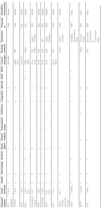
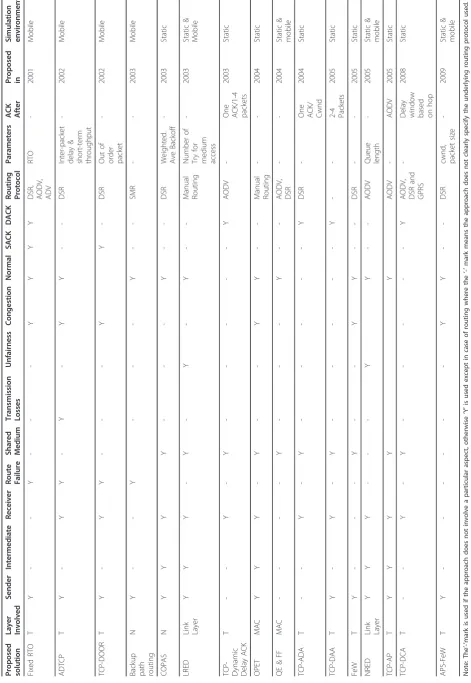
Based on the cross-layer and layered categorisation, Tables 1 and 2 provided in Section 4 summarize the dif-ferent proposals in more detail for quick overview. This tabular representation specifies the different characteris-tics of each proposal, such as which layer(s) is(are) involved in the proposal and clarifies whether the pro-posal is sender side, receiver side, or whether both sen-der and receiver are involved. The above tables also show whether or not a proposal relies on the involve-ment of intermediate nodes for feedback.
Now, let us explain that what is the difference between the cross-layer and layered approaches. The International Standards Organization (ISO) established a framework known as the open system interconnection (OSI) reference model aiming to standardize communi-cation systems. The OSI model consists of seven layers each with specific functionalities. From bottom to top, these layers are the physical, data link, network, trans-port, session, presentation and application layers [20]. The objective of cross-layer design is to pass informa-tion from lower layers to upper layers to facilitate deci-sion making in upper layers for better performance of the network. Passing information in such a way is a vio-lation of the OSI reference model, because, according to OSI model, each layer must perform its task indepen-dently. This attempt to violate the principles of the OSI reference model is called the cross-layer design
approach [21], while its opposite approach is called a layered approach. In [21], which is mainly focussed on the complexity of cross-layer design, those authors state that the traditional layered architecture is unable to
TCP
make efficient use of wireless network resources and, as a result, cross-layer design has been adopted to provide optimized operations in heterogeneous wireless environ-ments. Cross-layered design has been adopted in various application areas. Those readers who are interested in understanding the various aspects of cross-layer design, such as its complexity and the communication overhead it introduces, are referred to [21]. In next two sections (i.e. 4.2 and 4.3), each proposal for improving the per-formance of TCP in a wireless ad hocnetwork is dis-cussed in detail.
4.2. Cross-layer approaches
The cross-layered proposals for TCP improvement in wireless ad hocnetworks are presented under their sec-ond-level subcategories.
4.2.1. Route failure
TCP-feedback (TCP-F)TCP-F [22] addresses the pro-blem of TCP’s inability to distinguish between the losses due to route failure and the losses due to congestion. If any node detects route failure, then it immediately informs the source about the route failure to avoid unnecessary activation of congestion control. When the network layer detects disruption in the route due to mobility, then it informs the source using a route failure notification (RFN) message. On receiving the RFN mes-sage, each intermediate node must prevent other packets from passing through the failed route. In addition, if at any intermediate node an alternate route to the destina-tion is available, then the intermediate node must divert the traffic onto this path and discard the RFN message; otherwise, the intermediate node forwards the RFN message towards the source node.
On the other hand, when an RFN message arrives at the source node, then the source must enter snooze state. In the snooze state, the source must (a) stop all kinds of transmission, (b) freeze its state variables, (c) start a route failure timer, and (d) wait to receive the route re-establishment notification (RRN). There are two ways for the source to come out of the snooze state: (i) On receiving the RRN message, the source breaks out of the snooze state, or
(ii) When the route failure timer expires, then the source breaks out of the snooze state.
Expiry of the route failure timer is the worst case as it causes retransmission of all the unacknowledged pack-ets. If there are a large number of unacknowledged packets, then it can lead to a burst of traffic and a highly contended situation. If the source changes to its active state on receiving an RRN message, it restores the timer to the frozen value, and the cwnd also remains the same. However, continuing the transmission with the same cwnd may not be suitable for the new path. Similarly, while resuming transmission with the old
values of timers, there is a chance that timeout occurs before receiving ACK for unacknowledged packets, which is a drawback
Explicit link failure notification (ELFN)The objective of ELFN [23] is to provide route failure information to the source to avoid unnecessary activation of congestion control. In [23], it is stated that one of the ways to inform a TCP sender about route failure is to use a
‘host unreachable’ ICMP (internet control message pro-tocol) message for notification. However, in a case of route failure, the routing protocol will send a route fail-ure message to the sender. The approach taken by ELFN is to piggy-back a route failure message for TCP on the routing protocol route failure message. The ELFN message contains the sender and receiver addresses and port numbers as well as the TCP seg-ment’s sequence number. To implement the ELFN scheme, the route failure message of dynamic source routing (DSR) [24] protocol was modified to piggy-back the route failure message for TCP.
When the TCP sender receives an ELFN message, it enters a ‘standby’mode by disabling its retransmission timers. To gain information about the route re-estab-lishment in the ELFN scheme, the sender sends a probe packet periodically in‘standby’mode. On arrival of ACK for the probe packets, the sender breaks out of the
‘standby’mode restoring its timers and continues trans-mission with its cwnd unchanged. In addition, it is sug-gested to assign a fixed value to the time interval between two consecutive probe packets, and this value should be a function of the RTT.
TCP-buffering capability and sequence information (TCP-BuS)Considering the problem of TCP’s inability to differentiate route failure losses from congestion losses, a scheme named TCP-BuS [25] was suggested to tackle the route failure losses. In TCP-BuS, the associa-tivity-based routing protocol (ABR) [26] is the underly-ing routunderly-ing protocol which is a source-initiated on-demand routing protocol. TCP-BuS is a feedback mechanism based on TCP-F [22] which includes reliable delivery of control messages and avoids the unnecessary retransmission of packets along the broken path. In this regard, TCP-BuS has the following five enhancement features compared to TCP-F:
(i) Explicit route notification: To inform the source about route failure, an explicit route disconnection noti-fication (ERDN) message is generated at a pivoting node (PN)–a pivoting node is a node which detects a route failure. The explicit route successful notification (ERSN) is used to notify the source about route re-establishment and to resume transmission from the source.
packets on route re-establishment. It is possible that timeout occurs for the buffered packets. Therefore, it is necessary to increase transmission timeout values to avoid timeout events. For ease of implementation, the proposed scheme just doubles the timeout values.
(iii) Selective retransmission requested by receiver for lost packets: When the retransmission timer value for the buffered packets at the source and along the path to the PN expires, it is adjusted to be double its current value. The lost packets are not retransmitted until the adjusted timer value expires. To handle the packet loss along the path from the source to the PN, an indication is made to the source so that it can retransmit the lost packets selectively before their timeout value expires.
(iv) Avoiding unnecessary requests for fast retransmis-sion: On route restoration, the destination can notify the source about the lost packets. In response, the source simply retransmits the lost packets. The packets buffered along the path from the source to the PN may arrive at their destination earlier than the retransmitted packets, but the destination continues to send duplicate ACK until the expected packets arrive at the destination (via the fast retransmit method adopted by TCP-Reno). In TCP-BuS, these unnecessary request packets for fast retransmission are avoided.
(v) Reliable transmission of control messages: It is suggested, for a reliable transmission of the control mes-sages, if a node ‘A’ sends an ERDN message to its upstream node‘B’ then the ERDN message should be forwarded by node‘B’to its upstream node and must be overheard by node ‘A’; otherwise, the ERDN message will be considered lost and node ‘A’will retransmit the ERDN message. A similar technique is adopted for the reliable delivery of ERSN messages.
Ad hoc TCP (ATCP)The ATCP [27] is a sender-side solution that addresses the problems of route failure, high bit error rate and congestion. It inserts a layer between the TCP and IP layers to maintain compatibil-ity with original TCP. ATCP monitors the network state
information provided by explicit congestion notification (ECN) [28] and ICMP ‘Destination unreachable’ mes-sages to make decisions. ATCP runs in one of four states: Normal, loss, congested and disconnected as shown in Figure 5. It starts in normal state and counts the number of duplicate ACKs. On receiving a third duplicate ACK, it stops forwarding the third duplicate ACK to TCP and puts TCP into ‘persist’mode. Also, when RTO is about to occur, ATCP puts TCP into‘ per-sist’mode and enters the loss state. In the loss state, it retransmits all the unacknowledged packets. When a new ACK arrives for any of these retransmitted unac-knowledged packets, it is forwarded to TCP which comes out of its ‘persist’mode and ATCP returns to its normal state.
Whenever ATCP observes that the ECN flag is on, it shifts to the congested state to activate TCP congestion control without any interruption. However, receipt of an ICMP ‘destination unreachable’ message means route failure, or network partition has occurred. In response, ATCP enters ‘disconnected’ state and puts TCP into
‘persist’mode. In disconnected state, probe packets are used periodically to detect route re-establishment. On route re-establishment, ATCP returns to its normal state and takes TCP out of ‘persist’ mode into normal mode. ATCP sets the cwnd to one segment, as in the TCP slow start phase, along the new path.
Exploiting cross-layer information awareness (ECIA)
The study carried out in [29] is based on TCP-ELFN and proposes two mechanisms for further improve-ments. In [29], it is stated that a number of data packets as well as ACK packets get lost before the sender goes to ‘standby’ mode. The loss of Data and ACK packets leads to retransmission timeout. Therefore, it is impor-tant for the network layer to be aware of these losses to help in reducing TCP timeout due to mobility-induced losses. In this regard, two mechanisms, namely, early packet loss notification (EPLN) and best-effort ACK delivery (BEAD) were suggested. In case of route failure,
if an intermediate node cannot salvage the data packet, then the task of EPLN is to send a notification which includes the sequence number of every dropped packet to the sender concerned. As a result, the TCP sender should disable its retransmission timer and retransmit the lost data packets with the lowest sequence number on route availability. In the same way, if ACKs are not salvaged by an intermediate node, then the task of BEAD is to notify the receiver that generated the ACK. In response, the receiver resends the ACK with the highest sequence number on route availability. The DSR routing protocol has been modified to implement the BEAD and EPLN mechanisms.
Enhanced inter-layer communication and control (ENIC) The scheme named explicit notification with ENIC [30] was proposed to solve the problem of TCP performance degradation due to route failure. ENIC uses an explicit route state notification (ERSN) mechan-ism for inter-process communication (IPC). The ERSN has two types of control messages: explicit route error notification (EREN), and explicit route recover notifica-tion (ERRN). For external process communicanotifica-tion, ENIC uses routing protocol messages to feedback the route status. Route request (RREQ), route reply (RREP) and route error (RERR) are the three types of external routing messages amongst different nodes.
On detecting a route failure, a node generates a RERR broadcast control message for all the related source and destination nodes, while intermediate nodes receiving this message will drop all the packets related to this failed route.
On receiving a RERR message, the source initiates a route recovery process by broadcasting a RREQ control message and stops the transmission of data packets (new and retransmission); In addition, it puts TCP into suspension state by freezing values of state variables and initializing the route recovery timer. If the source does not receive a RREP before the expiry of the route recov-ery timer, then the route recovrecov-ery process is repeated until the pre-specified maximum number of attempts allowed for route recovery is reached. On making the maximum number of unsuccessful attempts allowed, the source closes the connection. On receiving the RREP message, the source breaks the suspension state and transmits all the unacknowledged packets, while return-ing all variables to their original states except the retransmission timer. This approach uses the DACK (delay acknowledgement) and SACK mechanisms.
Preemptive routingA scheme, named preemptive rout-ing [31], which addresses the problem of route failure, tries to detect when route failure is near to occurring to potentially avoid the disconnection altogether. The sig-nal strength is used for determining closeness to route failure. When the signal strength goes below a specified
threshold (called the preemptive threshold), then it means that link failure is near to occurring. In such a situation, the node concerned must inform the source; as a result, the source initiates discovery of a new route.
Ping-pong messages were proposed to measure the signal strength and avoid initiating a false route failure warning. Ping-pong messages are actually small size packets used for probing a link state. A node sends a ping message and receives the pong message in response from the other node, to measure whether signal strength is either below or above the particular threshold. DSR
and ad hocon-demand distance vector (AODV) [32]
routing protocol were modified to implement this tech-nique, and the modified versions are called preemptive DSR and preemptive AODV routing, respectively.
however, the authors of ATRA claim that ATRA will work with all on-demand routing protocols.
Signal strength-based link managementThe objective of the scheme proposed in [34] is to overcome packet loss due to mobility and packet loss due to false route failure information. When, in IEEE 802.11 MAC proto-col, a sending node fails to establish RTS/CTS hand-shake with a receiving node after a specified number of attempts due to channel contention, then the sending node notifies the network layer that the path is not available and drops the packet. This type of route failure notification is a wrong (false) notification, because the path is available, but the sending node is unable to establish RTS/CTS handshake because of channel con-tention. In the proposed approach, it is suggested to double the number of attempts for medium access if there is a high probability that the neighbouring nodes are still within the transmission range of each other. Each node maintains a record of the signal strength of its neighbouring nodes to observe how the signal strength changes over time and computes the probabil-ity of a node being present within its transmission range.
Two other mechanisms were also proposed in [34] known as proactive and reactive link managements (LM). The aim of proactive LM is to inform the routing protocol that a link is near to breaking, and the routing protocol then informs the packet source. As a result, the source stops sending packets, and route discovery is initiated. Reactive LM increases the transmission range of a node to restore a broken link for a short time to give a chance to the packets in transit to traverse the high power link. For successful transmission, it is neces-sary that both the nodes (the nodes between which the route failure has occurred/is near to occurring) shift to a high transmission power to have an RTS/CTS hand-shake. However, a node must shift quickly to the lower transmission range to communicate with other nodes. The nodes are not allowed to broadcast a RREQ mes-sage with high transmission power because the new route must contain a default power link. AODV is used as the routing protocol. In [34] changes were made at the MAC and routing layers to implement the proposed mechanisms.
Comparison Nine cross-layer proposals have been stu-died: TCP-F, TCP-BuS, ELFN, ATCP, ECIA, ENIC, pre-emptive routing, ATRA, and signal strength-based LM. These proposals address the problem of route failure and seek to ensure that route failure and congestion losses are not misinterpreted.
The TCP-F mechanism used the route failure and route re-establishment notification to inform the sender about route status. The TCP-F mechanism also has the route recovery timer. When this timer expires before
receiving route re-establishment notification, then the sender retransmits all the unacknowledged packets. This retransmission of unacknowledged packets can lead to the injection of a burst of packets into the network and can create network congestion. In contrast, restoring variables to their original values on receiving RRN can lead to two types of problems: (1) it is possible that the new path will be long and timeout occurs; (2) the band-width will be different on the new path, which may be unsuitable for continued transmission with same cwnd. TCP-BuS is based on TCP-F using the network layer notification about route failure and re-establishment. TCP-BuS provides a reliable mechanism for control messages over TCP-F and provides selective ACK for the retransmission of lost packets.
A group of four approaches ELFN, ATCP, ECIA and ENIC does not use the route re-establishment mechan-ism like TCP-F and TCP-BuS. The ELFN mechanmechan-ism is the first approach in this group. It modified the route failure message of DSR to piggy-back the route failure notification for TCP, while using the probe packet to detect route re-establishment. On route availability, ELFN comes out of standby mode into normal mode, restoring the retransmission timer and cwnd to their original states. It is possible that the original retransmis-sion timer and cwnd may not be suitable for the new path as is the case with TCP-F. The authors state that for efficient performance of a network, it is better to restore the cwnd to its original state (the state before the route failure) rather than restore the cwnd to its initial size as in the slow start phase. Thus, both the TCP-F and the ELFN mechanisms fail to find out the actual size of the cwnd required on the new path. In ELFN, there is no mechanism to divert the traffic on intermediate nodes as in TCP-F.
ATCP also uses the probe packet to detect route re-establishment and shrinks the cwnd on route re-estab-lishment, which causes a slow down in the traffic and can lead to poor utilization of network resources, espe-cially on long paths. ATCP and ELFN are contradictory in adapting the size of cwnd on the new path, and further analysis is needed to determine which option is the best. When ATCP moves to disconnected or loss state, it puts the sender in ‘persist’ mode. There will be no transmission in ‘persist’mode. Because ATCP stops the forwarding of ACK packets to TCP in ‘persist’ mode, it causes the clocking mechanism of TCP to be lost.
sender/receiver transmits those data/ACK packets to avoid transmission timeout.
The approach named ENIC is also based on ELFN to notify both the sender and the receiver about the route failure. However, it uses broadcast messages for all the related source/destination nodes. In ENIC, the inter-mediate nodes drop the packets on receiving the route failure message, which is the opposite strategy to that adopted in TCP-BuS which buffers the packets, while TCP-F diverts the traffic if another route is available. Therefore, there are three opinions on what to do with the packets on intermediate nodes in the event of route failure, which necessitates further evaluation of these approaches.
The three approaches named preemptive routing, sig-nal strength-based LM and ATRA are based on sigsig-nal strength to tackle route failure. The significance of these three approaches is that they inform the sender of route failure before it occurs.
In preemptive routing, when the signal strength between two nodes decreases below a specified thresh-old, then the source is informed before the path failure occurs to minimize the delay in establishing a new route. One of the unfavourable aspects of this approach is that it uses ping-pong control messages which create an extra overhead on the channel. Furthermore, the per-formance of this approach is dependent on the selection of the preemptive threshold. If the value is too low, then there will not be enough time to find an alternative path. If the value is too high, then it causes unnecessary route discovery to be initiated and unnecessary usage of the medium.
In the signal strength-based LM scheme, route discov-ery is also initiated before the failure of the current route. At route failure, an increase in the transmission power of the two nodes allows the packets to traverse the path. However, in the signal strength-based LM scheme, the second mechanism introduced, which is to double the number of reattempts for medium access, is suspect. This is because of wrong estimation in the sec-ond mechanism, which just causes unnecessary attempts for data transmission.
The third approach based on signal strength is ATRA. The route failure and re-establishment mechanisms of ATRA and ELFN are the same, but ATRA notifies all the sources that used the failed path in lastT seconds of the route failure, whereas ELFN notifies only the source from which connection the packet was dropped. It is difficult to decide at this point without any further evaluation which technique is the best.
4.2.2. Congestion and transmission losses
Restricted congestion window enlargement (TCP/ RCWE) TCP/RCWE [35] employs the ELFN [23] mechanism to tackle route failure. Its innovation is to
tackle the congestion and packet loss due to a high bit error rate, and, for this reason, it is discussed under the category of ‘Congestion and transmission losses.’In the TCP/RCWE mechanism, a network state estimator (NSTATE) has been introduced to detect whether a net-work is congested or not, which is based on the RTO and can be represented as
NSTATE = true if RTOnew≤RTOold
NSTATE = false if RTOnew>RTOold
According to the NSTATE, if the current RTO (RTOnew) is greater than the previous one (RTOold), it means that the network is congested. In this case, the sender should continue its transmission without any increase in the size of the cwnd. If the current RTO is less than or equal to the previous one, then it means that there is no congestion and the sender can increase the size of the cwnd. During the running phase, the TCP/RCWE scheme will be in one of the three states, i.e. Normal, Congested, and Link break, see Figure 6. In the congested state, the sender decision is based on the NSTATE as mentioned above. On the other hand, the aim of the Link break state is to tackle route fail-ure, but TCP/RCWE is totally dependent on the mechanism of ELFN in this case; there is no integra-tion of any new idea for handling route failure in TCP/RCWE.
Cross-layer congestion control for TCP (C3TCP) Klia-zovich et al. [36] proposed a C3TCP scheme which is a feedback system to mitigate the problem of network congestion. C3TCP is focussed on limiting the amount of data emitted to the network in order to avoid conges-tion. In this regard, C3TCP measures the available band-width at each node, and the delay encountered by each Link, and the gathered information, is inserted into the option field of the MAC header. After measuring band-width for the first node and its link delay, the second node must compare the bandwidth of both nodes and pick the minimum bandwidth, while the delay on the second link is summed with the delay on the first link, and this operation is repeated at each node. When a TCP data packet reaches its destination node, its MAC header will contain information on the minimum avail-able bandwidth and the link delay for the whole path. When the destination node replies with TCP ACK, the gathered information is also transmitted to the sender. Based on the bandwidth and the delay information, the sender should adjust its outgoing traffic. It is noted that the Link Delay is obtained as the sum of the forward and backward delays.
increase or decrease the injection of packets into the network, while incorporating the ELFN mechanism to tackle the route failure. During simulation, TCP/RCWE was compared with TCP to establish that its perfor-mance is better. However, for route failure, TCP/RCWE is totally dependent on the ELFN mechanism, and the simulations failed to show any improvement of TCP/ RCWE over ELFN. C3TCP is measuring the end-to-end delay during each packet transmission and finding out the minimum available bandwidth along the path, and using the information to inject the data into the network accordingly. To compute the transmission rate, this mechanism uses the bandwidth-delay product which is the product of a data link’s capacity and its end-to-end delay. The idea behind this proposal seems quite good, but the demand of this proposal is to provide optional field support to the existing IEEE 802.11 MAC protocol. 4.2.3. Shared medium
Wireless congestion control protocol (WCCP) Zhai et al. [10] proposed a scheme named WCCP to handle the contention problem. The authors of [10] state that con-tention is the main reason for TCP unfairness and throughput instability. WCCP uses the channel’s busy-ness ratio to characterize the network utilization and congestion status. WCCP measures the available band-width in the shared channel and, based on this, inter-node and intra-inter-node resource allocation schemes are proposed to determine the available resources for each node and each flow. WCCP uses two modules, one at the transport layer to replace the TCP windows algo-rithm with a rate based algoalgo-rithm, while the other is between the network and the MAC layers to monitor and possibly modify the feedback field in each TCP data packet. This field is sent back to the sender in an ACK and, on the basis of received feedback, the sender regu-lates its transmission rate.
TCP contention control (TCTC) In the TCTC [37] scheme, the problem of TCP intra-flow instability, which lies in overloading the network by sending more data than the capacity of the channel, has been addressed. Intra-flow instability refers to a situation where the successive transmissions of packets in a single flow interfere with each other and, as a result, a large number of packets are dropped. To dynamically adjust the data transmission rate and provide intra-flow stabi-lity, the TCTC technique monitors two things at the receiver end for a fixed probe interval, one being the achieved throughput and the other the level of conten-tion delay experienced by packets. Based on these obser-vations, the receiver estimates the optimum amount of traffic and passes this information to the sender. As a result, the sender will regulate its transmission accord-ingly. Moreover, the contention delay-measuring time starts when a node places the first fragment of a packet at the beginning of a buffer and continues until the packet leaves the buffer for actual transmission. If a packet is dropped because of unsuccessful RTS/CTS handshake, then the delay is added to the contention delay of next packet. To estimate the optimum amount of traffic that should be sent by the sender, TCTC defines a new variable called the TCP contention win-dow (ctwnd), the value of which is computed according to the following four stages of the TCTC scheme:
(i.) Fast probe: After connection establishment, TCTC enters the fast probe phase. In this phase, the ctwnd increases exponentially as it does in the TCP slow start phase. Whenever TCTC observes severe contention, then it enters a fast probe phase.
probe phase. In this phase, the aim of the receiver is to increase the amount of network traffic by adding one MSS to thectwndafter each probe interval.
(iii.) Light contention: When the receiver observes that there is an increase in the achieved throughput and con-tention delay, it means that the network is overloaded and, as a result, the TCTC scheme adopts the light con-tention phase. In this phase, the receiver reduces the amount of network traffic by subtracting one MSS from
the ctwnd, while ignoring the decrease in the
throughput.
(iv.) Severe contention: If the contention delay increases and the throughput decreases, then it is an indication of severe contention. At this stage, TCTC sets its ctwnd to 2*MSS to force the sender to slow down the data transmission rate, and TCTC enters a fast probe phase.
Comparison In this group, there are two cross-layer solutions, named WCCP and TCTC, to tackle the con-tention problem that arises because of the shared med-ium. WCCP uses the busyness ratio of the medium to measure the network utilization and congestion status, and then uses the measured value to adjust the trans-mission rate. The TCTC scheme measures the through-put achieved and the contention delay experienced by the packets on receiver side for a fixed time interval and then computes the optimum transmission rate for the sender. Thus, TCTC is totally dependent on the value of the time interval, if measurements are taken on expiry of a properly selected time interval well then; otherwise, the network will be underutilized or more congested.
4.3. Layered approaches
The layered proposals for TCP improvement are now presented under their second-level subcategories. 4.3.1. Route failure
Fixed RTODyer and Boppana [38] analysed the perfor-mance of TCP over three routing protocols which included two on-demand routing protocols named DSR [24] and AODV [32], and an adaptive distance vector (ADV) [39] routing protocol that combines an on-demand approach with proactive distance vector rout-ing. It was observed that ADV performed well under variety of conditions compared to the on-demand rout-ing protocols, DSR and AODV.
Moreover, a scheme is proposed in [38] to distinguish between route-failure losses and congestion losses which is a sender-side scheme named fixed-RTO (retransmis-sion timeout). However, ADV does not get any benefit from this scheme because its route repair does not occur fast enough. In traditional TCP, RTO increases exponentially, but in fixed-RTO, on the expiry of two RTOs consecutively without receiving the ACK, it is assumed that route failure has occurred, and then the
unacknowledged packets are retransmitted without increasing the RTO for a second time. According to [38], Fixed-RTO is only applicable in wireless environ-ments and can be implemented easily in UNIX, by mod-ifying thegetsockoptand setsockoptfunctions.
TCP-friendly transport protocol The scheme proposed in [40] is an end-to-end approach named ADTCP which tries to detect congestion, route disconnection/failure and channel errors, and trigger an appropriate action. Moreover, ADTCP uses two metrics, the inter-delay dif-ference (IDD), and the short-term throughput (STT) to detect network congestion. The IDD is the interval between two consecutive packets arriving at the receiver end. An increase in this interval is a sign of network congestion. STT is the throughput measured for a speci-fic interval in the near past at the receiver end. A decrease in STT is also a sign of network congestion. These two metrics are used in combination to deter-mine the network state which is either congested or not, and how to regulate the data transmission. On the other hand, the out-of-order packets and loss ratio are used for detecting route changes and channel losses. The feedback is provided to the sender in ACK which then reacts accordingly.
TCP detection of out-of-order and response (TCP-DOOR): Wang et al. [41] proposed a transport-layer scheme named TCP-DOOR, which is a pure end-to-end approach, to tackle the problem of route failure. In con-ventional TCP, when a sender sends packets, they should arrive in sequence at the receiver end. Otherwise, the receiver assumes that packets have been lost. How-ever, on receipt of out-of-order packets, TCP-DOOR assumes that a route change has occurred.
In a TCP session, the delivery of out-of-order packets can happen in either direction, i.e. it can happen with data packets or ACK packets. The sender detects out-of-order delivery of ACK packets from the ACK sequence number, since every new ACK sequence num-ber must be greater than the previous one if the ACKs are received in correct order. However, two duplicate ACKs have the same contents. Therefore, additional information is required to detect out-of-order delivery. In this regard, it is proposed to add a one byte TCP option to the TCP-ACK header called an ACK duplica-tion sequence number (ADSN). The initial value of the ADSN will be zero with each ACK, while sending a duplicate ACK for the same sequence number will trig-ger an increment in the ADSN number.
including retransmitted data packets. Thus, in a case of retransmission, the TPSN will be different from the pre-vious one. The second method is to add a time stamp to each data packet instead of a TPSN.
On detecting out-of-order events, the receiver must inform the sender by setting the out-of-order bit in the TCP-ACK. After the sender knows about the out-of-order event, it can take the following two actions: the sender disables the congestion control for a pre-defined time and the values of state variables remain unchanged, and as a second action (known as instant recovery), TCP sender adopts a somewhat older state, which was invoked in the past T seconds. It should be clear that TCP-DOOR is a derivative of TCP-SACK.
Backup path routingLim et al. [42] proposed a backup path routing protocol to improve path availability in mobile environments. In [42], the performance of TCP was analysed over an on-demand multipathad hoc rout-ing protocol named split multipath routrout-ing (SMR) [43] which is an extension of DSR protocol. It was observed that the multipath routing is detrimental to the perfor-mance of TCP. As a result, the backup path routing protocol strategy was suggested.
SMR uses two approaches to discover a new path. In the first approach, a new route discovery process is initiated as soon as a route becomes invalid. In the sec-ond approach, a route discovery process is initiated, when all routes become invalid. Through analysis, it is found that the second approach is better than the first one. Therefore, it is adopted in the proposed backup path routing protocol.
In addition, it was reported in [42] that TCP per-formed better when a single path was used for a TCP connection compared with using multiple paths for a single TCP connection. This is because forwarding data through different paths maximizes the chance of out-of-order packets, while TCP generates duplicate ACK in case of out-of-order packets and, as a result, there will be data retransmission. Moreover, each route has differ-ent RTT, and so there will be inaccurate average RTT calculation. Therefore, in the proposed backup path routing protocol, it is suggested to discover two paths between the source and the destination for each connec-tion. However, only a single path is used for data trans-mission and the second one maintained as a backup path to minimise the chance of route unavailability. To select a primary path and a backup path, two selection options were suggested. The first option is to select the hop path as the primary path and the shortest-delay path as the backup path. In the second option, the shortest-delay path is selected as the primary path and the maximally disjoint path as the backup path. In both cases, it is a good practice to select paths where both
the primary and the backup paths have minimum over-lapping nodes.
ComparisonFour layered proposals addressing the pro-blem of route failure have been studied in this section. Three of them named Fixed RTO, TCP-DOOR and AD-TCP are transport-layer solutions, while backup path routing is a network-layer solution. In Fixed RTO when two consecutive RTOs expire, it is assumed that the path is not available, and the packet is retransmitted without increasing the RTO. Thus, it has an effect like an ELFN-probing packet, but Fixed RTO is easier to implement than ELFN. The second transport-layer approach named TCP DOOR has been shown to deliver a 50% improvement in throughput, but it fails to set the transmission rate properly on the new path.
The AD-TCP mechanism uses the IDD and short-term throughput to detect network congestion, while out-of-order packets and loss ratio are used for detect-ing route change and channel losses. However, from an implementation point of view, 300 lines of code are needed for AD-TCP which adds an extra computational load on the system. In contrast, the backup path-routing mechanism has been shown to deliver a 30% improve-ment in TCP performance, while discovering two paths for transmission. One of these paths is used for trans-mission and the other one as a backup path. Thus, the data and ACK packets of a connection are forwarded through the same path for better performance, but the TCP-COPAS (TCP-contention-based path selection) mechanism, which will be discussed in Section 4.3.3, contradicts this strategy.
4.3.2. Congestion and transmission losses
Fractional window increment (FeW) The scheme is proposed by Nahm et al. [44]. First of all, it was ana-lysed how the network congestion and MAC contention effect the interaction between TCP and on-demand ad hocrouting protocol. It was observed that one of the reasons for TCP’s low throughput lies in its window mechanism. By nature, TCP is aggressive in increment-ing the cwnd, which causes network congestion and channel contention.
ratio, so that TCP can achieve a high throughput. The mathematical equation of [45] was also used for the eva-luation of FeW, and it was found that it could increase the throughput compared to standard TCP.
TCP with adaptive pacing (TCP-AP)TCP-AP[46] is a novel congestion control algorithm to handle the injec-tion of data into the network and avoid large bursts of packets. TCP-AP is a pure end-to-end approach that seeks to keep a proper pacing between the packets before injecting them into the network. To introduce adaptive pacing between successive packets transmis-sion, TCP-AP uses an estimation of the four-hop propa-gation delay (FHD) and the coefficient of variation of the recently measured round trip times (RTTs). The FHD is the time a packet takes, after its transmission, to arrive at a node four hops away from the source node. It is claimed that TCP-AP achieved up to 84% increase in the goodput.
Adaptive packet size on top of FeW (APS-FeW)Wang et al. [47] studied the window adjustment mechanism of FeW [44] and found that it cannot make full use of its predicted window. The fractional part of the cwnd has no effect on transmission and, consequently, a certain amount of predicted network capacity is wasted. Thus, the FeW scheme is too strict in limiting the amount of data transmission. Therefore, an adaptive packet size (APS) [47] scheme was proposed to fully utilize the size of the predicted window. The packet size in FeW is fixed, whereas APS-FeW can adapt the packet size to the current predicted window. APS uses equation (A) below to compute the current packet size.
packetsize = ((cwnd ×initPacketsize)/cwnd ) (A)
where initPacketsize_ is the initial packet size which has a fixed value,cwnd_is the cwnd size andpacketsize_ is the current packet size. The TCP sender uses equa-tion (A) to compute the new packet size when there is any change in the cwnd. Moreover, when retransmission timeout occurs, the TCP sender goes into the slow-start phase resetting the cwnd to 1. The TCP source needs to repack the data in its buffer with an initial packet size. When the TCP source enters the fast retransmit phase due to three duplicate ACKs, then there is no need to repack the lost data packet, but just to transmit the packets in the buffer. The current packet’s size never goes beyond double that of the initial packet size
ComparisonIn this group, three approaches have been studied, namely TCP-AP, FeW and APS-Few. The objective of these approaches is to limit the injection of data into the network to avoid network congestion, and to reduce the packet losses. The TCP-AP approach uses an estimate of the FHD between the successive packets and achieves an up to 84% improvement in goodput
over TCP NewReno. On the other hand, instead of introducing some pacing mechanism to slow down the traffic and avoid network congestion, FeW and APs-FeW both limit the increase in the cwnd to reduce the aggressiveness of TCP. However, FeW is too restrictive in limiting the cwnd, to the point of wasting some pre-dicted network capacity, and so the aim of APS-FeW is to fix this problem with the FeW mechanism to achieve a higher throughput.
4.3.3. Shared medium
COPASCordeiro et al. [48] proposed a scheme named contention-based path selection (COPAS) to handle the problem of channel contention by forwarding the data and ACK packets through different least-contended paths. For route selection, two criteria were adopted: first of all to find out all the possible routes between the source and the destination, then select two disjoint routes for forwarding data and ACK packets. To select the least-contended routes, COPAS monitors the paths continuously for channel contention and diverts the traffic towards the least-contended path. To determine the contention in its neighbourhood, each node counts how many times it has been backed off during the last
TBACKOFF seconds, and then computes the weighted
average (μBACKOFF). Each node appends the weighted average to the non-duplicate RREQ packet, and a deci-sion is made on the basis of this weighted average as to which path is the least contended. The COPAS mechan-ism is applicable to any source initiated on-demand routing protocol such as AODV and DSR.
Dynamic delay acknowledgement (DD ACK) Altman et al. [49] proposed a scheme named DD ACK which is a receiver-side solution for dealing with the contention problem by limiting the number of ACK. This technique is based on RFC 1122 [50] which defines a standard for generating an ACK afterd(d = 2) packets or after some specific time ifd packets are not received in this time. In DD ACK, d varies from 1 to 4. To begin with, DD ACK generates an ACK for one packet (d = 1), and then gradually moves towards generating an ACK after every four packets (d = 4). Moreover, [49] defines three thresholds l1,l2 and l3 to control the increase in the value of dsuch that d= 1 if the sequence numberNis less thanl1; if the sequence numberNis such thatl1 < N < l2, thend =2;d = 3 ifl2 <N < l3;andd= 4 when
l3 < N. Whendreaches 4, then there is no mechanism to bring it back down in this scheme. Suppose at some point the TCP connection enters a slow start phase, whered = 4, then more time is required to increase the cwnd to achieve good utilization of the available bandwidth.
consists of two mechanisms. The first mechanism pro-vides high-priority medium access to the current recei-ver to avoid intra-flow contention at each node. The second mechanism is backward-pressure scheduling which restricts the forwarding node from sending more packets to its downstream node. The downstream node will be ready to receive more packets for a particular flow when it forwards the previous packets of this flow. To restrict the forwarding node, each downstream node receives packets from the forwarding node up to a parti-cular limit named the backward-pressure threshold. After reaching the backward-pressure threshold, a node sends a negative-clear-to-send (NCTS) message as a response to a RTS message instructing the upstream node to stop forwarding further packets. To resume the transmission after a NCTS message, the receiver initi-ates the three-way handshake mechanism CTS/DATA/ ACK instead of the RTS/CTS/DATA/ACK handshake mechanism. In the CTS/DATA/ACK three-way hand-shake mechanism, the receiver should clearly identify the source address and flow ID.
Quick exchange (QE) and fast-forward (FF) (QE & FF)
Two MAC layer mechanisms named QE and FF were proposed by Berger et al. [52] to tackle the problem of self-contention. QE aims to handle the problem of inter-flow self-contention (contention between packets of the same connection moving in opposite directions). FF aims to overcome intra-flow self-contention (conten-tion among packets of the same connec(conten-tion moving in the same direction).
The quick exchange mechanism allows the two pack-ets to be exchanged through a single RTS/CTS control message as shown in Figure 7, which adds an extra data packet (DATA2) to the normal exchange procedure of RTS/CTS/DATA/ACK, where DATA2 is a packet mov-ing in the opposite direction to that of packet DATA1. In addition, the time field of the CTS message is modi-fied by adding an extra time interval to reserve the
channel for transmission of DATA2. All the neighbour-ing nodes should update their status on receivneighbour-ing the CTS message. After receiving the data packet DATA1, the receiver replies with ACK and must piggy-back the DATA2 packet with the ACK. Afterward, the original sender must acknowledge the DATA2 packet to com-plete the transmission process. If there is no DATA2 packet to transmit in the opposite direction, then the nodes continue transmission using the original RTS/ CTS/DATA/ACK mechanism.
The FF mechanism is shown in Figure 8, where the RTS/CTS taking place is normal at the beginning, but during the ACK for the first set of DATA1 packets, the receiver sends the RTS messages with a piggybacked ACK if it has data packets to send in the opposite direction.
TCP-ADA (TCP with adaptive delayed ACK) The solution proposed by Singh et al. [53] is known as TCP-ADA, which is a receiver-side solution. The authors claim that TCP-ADA is the best choice for generating an ACK for one cwnd to handle the problem of channel contention and collision among Data and ACK packets.
TCP dynamic adaptive ACK (TCP-DAA) strategy
TCP-DAA [54] is another solution that belongs to the category of generating a delayed ACK, which generates an ACK according to the channel conditions. If channel conditions are good, then the ACK is delayed for up to four packets; otherwise an ACK is generated after two packets have arrived. If out-of-order packets are received or packets are filling the gaps in the sequence space of packets in the receiver buffers, then an ACK is gener-ated immediately. Fast retransmission of packets takes place after receiving three duplicate ACKs in conven-tional TCP. In TCP-DAA, this number is decreased from three to two packets to minimize unnecessary retransmission. Figure 9 shows how the receiver dynamic window (dwin) changes. Under normal condi-tions, it is maintained at a maximum size of four
packets. When there is any packet drop, then TCP-DAA reduces the dwinsize to two, i.e. it generates an ACK after two packets. Afterward the size of dwinis incre-mented to delay ACK up to three packets and then four.
TCP-delayed cumulative ACK (TCP-DCA)Chen et al. [55] proposed a scheme known as TCP-DCA which also belongs to the category of generating a delayed ACK. DCA is inspired by the idea underpinning TCP-DAA. It tries to determine the delay window based on the hop count. For a short path (h≤3, h represents the number of hops) TCP-DCA will delay an ACK for the whole cwnd to achieve the best performance. For paths where 3 <h≤9, TCP-DCA will send an ACK after five packets; if h≥ 10 then an ACK is sent after three pack-ets. The delay windows proposed by TCP-DCA based on hop count are listed in Table 3.
The simulations of [55] used each of AODV, DSR and greedy perimeter stateless routing (GPRS) [56] as the routing protocol.
Link randomly early detection (LRED) Fu et al. [57] observed that there exists an optimal cwnd size for which TCP can achieve the best performance, but that, instead of trying to find the optimal cwnd size, TCP increases its cwnd aggressively, which leads to packets
being dropped at the link layer. It is also observed in [57] that the drop of packets due to buffer overflow is rare in wireless networks if the buffer size at a node is greater than 10 packets. Actually, in wirelessad hoc net-works, medium contention is the major cause of dropped packets, which is also an indication that the network has been overloaded. As a solution, two mechanisms were proposed to address contention and unfairness named LRED and adaptive pacing.
The LRED algorithm maintains the average number of attempts for medium access. When the average number reaches a particular threshold, then the packets’ drop-ping probability is computed according to the random early detection (RED) [58] algorithm. The RED algo-rithm is a mechanism for wired networks to drop pack-ets from the router queue, when the queue size becomes greater than a particular threshold. In notifying the sender, in the RED algorithm, the dropped packets are taken to be a sign of congestion, whereas in the LRED algorithm, they are taken to be a sign of contention.
The second mechanism, adaptive pacing, is used for regulating the data flow in a more balanced and fair way. Adaptive pacing adds an extra interval to the back-off time, which is equal to the transmission time of the previous data packet. Addition of this extra interval to the backoff time causes a slowdown in the data flow rate and, as a result, poor utilization of the network resources.
Neighbourhood randomly early detection (NRED)
Contention among the nodes due to the shared medium also leads to the problem of unfairness; in this regard, Figure 8802.11 with Fast Exchange[52].
Ack count
Figure 9 Receiver dynamic window for delaying packets in TCP-DAA[54].
Table 3 Delay window at the TCP-DCA receiver
Path length (h) Delay window limit
h≤3 cwnd
3 < h≤9 5


![Figure 5 State transition diagram for ATCP at the sender [27].](https://thumb-us.123doks.com/thumbv2/123dok_us/952455.1116419/10.595.61.541.572.714/figure-state-transition-diagram-atcp-sender.webp)
![Figure 6 State diagram of TCP/RCWE [35].](https://thumb-us.123doks.com/thumbv2/123dok_us/952455.1116419/14.595.56.546.88.262/figure-state-diagram-of-tcp-rcwe.webp)
![Figure 7 802.11 with Quick Exchange [52].](https://thumb-us.123doks.com/thumbv2/123dok_us/952455.1116419/18.595.56.539.567.712/figure-with-quick-exchange.webp)
![Figure 8 802.11 with Fast Exchange [52].](https://thumb-us.123doks.com/thumbv2/123dok_us/952455.1116419/19.595.302.538.667.724/figure-with-fast-exchange.webp)
