Study of the ballistic behaviour of UHMWPE composite material:
experimental characterization and numerical simulation
Hakim Abdulhamid1, *, Paul Deconinck1, Pierre-Louis Héreil1 and Jérôme Mespoulet1 1Thiot Ingénierie, Route Nationale, 46130 Puybrun, France
Abstract. This paper presents a comprehensive mechanical study of UHMWPE (Ultra High Molecular Weight Polyethylene) composite material under dynamic loadings. The aim of the study is to provide reliable experimental data for building and validate the composite material model under impact. Four types of characterization tests have been conducted: dynamic in-plane tension, out-of-plane compression, shear tests and plate impact tests. Then, several impacts of spherical projectiles have been performed. Regarding the numerical simulation, an intermediate scale multi-layered model (between meso and macro scale levels) is proposed. The material response is modelled with a 3d elastic orthotropic law coupled with fibre damage model. The modelling choice is governed by a balance between reliability and computing cost. Material dynamic response is unconventional [1, 2]: it shows large deformation before failure, very low shear modulus and peeling strength. Numerical simulation has been used both in the design and the analysis of tests. Many mechanical properties have been measured: elastic moduli, failure strength and EOS of the material. The numerical model is able to reproduce the main behaviours observed in the experiment. The study has highlighted the influence of temperature and fibre slipping in the impact response of the material.
1 Introduction
The use of polymer-based composite like polypropylene, aramid and ultra-high molecular weight polyethylene (UHMWPE) has become more and more popular in light weight armours. Due to their composite structure, such type of material can exhibit diverse failure modes depending on the characteristics (geometry, material, velocity) of the threats. Therefore, it becomes convenient to use numerical tool for the analysis and optimisation of such type of armour against different threats. Many studies have been conducted on UHMWPE composite material dynamic response. For example, [1] investigated in-plane deformation behaviour and [2] shock propagation in-fibre direction. Out-of-plane compressive response has been studied by [3] in static and [4] under shock loading. Furthermore, a comprehensive literature is available regarding, the ballistic response of such material [5-6]. [6] used a numerical model combining orthotropic behaviour and EOS for the simulation of ballistic response on UHMWPE plate.
This paper describes a study combining experimental and numerical tools to develop a ballistic FE model for UHMWPE composite panel. The material mechanical response and failure mode is investigated under four types of dynamic solicitation: in-plane tension, out-of-plane compression, out-of-plane shear
input of an orthotropic material law coupled with fibre damage. The paper is divided into two main parts, the first section details the characterisation tests with the corresponding FE model and the second section deals with the ballistic tests and simulation. Some results had to be normalized to comply with the confidentiality obligations of the study.
2 Material characterisation
The material is available as a stratified composite panel of UHMWPE unidirectional fibres. It is the strongest fibre available in terms of strength to weight ratio. The panel is obtained from multiple stack 0°/90° plies impregnated with thermoplastic matrix. All the tests conducted in this study have been realised from the same lot of material.
2.1 Dynamic tension
90°), any attempts to load the 45° direction fails due to a very low in-plane shearing strength of the material. Table 1 shows the normalized tension failure strength of the composite along the fibre directions. The values have been normalized by a mean tensile strength obtained from quasi-static tests. An average 10 % increase of the strength is observed during dynamic tests.
Table 1. Normalized tensile failure strength.
Test No 1 2 3 Avg. Std.
dev. Normalized σ11fail &
σ22fail 1.05 1.08 1.17 1.1 0.06
Fig. 1.Dynamic tensile tests configuration.
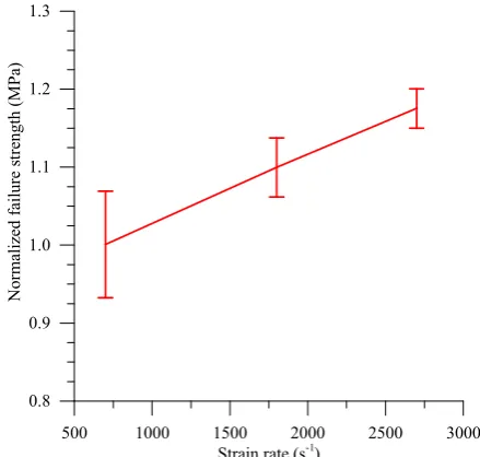
2.2 SHPB compression
Compression tests are conducted on Hopkinson bars. Specimens of 10x10x5 mm3 dimensions are cut with waterjet from the main plate. Compressive loading is applied in the out-of-plane (o-o-p) direction of the specimen.
Eight tests are realised with three values of striker speed to target three different mean strain rates: 3000, 4500 and 5600 s-1. Figure 2 shows the evolution of the
strain rate during a SHPB test. A strain rate peak is reached between 0.05 and 0.10 of deformation, then it decreases until failure. For all tests, the compressive stress versus compressive strain of the material exhibits a linear response until failure. An increase of the failure strength is observed at high strain rate (Figure 4). At 2700 s-1, the failure strength increases about 20 %. The
o-o-p compression failure mode of this composite material is quite unconventional. Failure is triggered by
0.00 0.05 0.10 0.15 0.20 0.25 0
1000 2000 3000 4000 5000 6000
Test 4 Test 5 Test 6
St
rai
n r
at
e (
s
-1 )
O-o-p compressive strain
Fig. 2. Evolution of strain rate during the o-o-p compressive test.
Fig. 3.Failure mode under compressive o-o-p loading.
500 1000 1500 2000 2500 3000
0.8 0.9 1.0 1.1 1.2 1.3
N
or
m
al
ized
fai
lu
re s
tren
gt
h
(M
Pa)
Strain rate (s-1)
Fig. 4. Strain rate effect on o-o-p compressive failure strength.
2.3 Dynamic shear
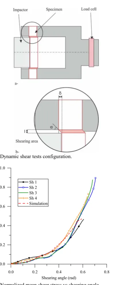
A mean o-o-p shear response is measured with the configuration presented in Figure 5a. A cylindrical specimen is clamped on its edge and impacted by a cylindrical projectile. The diameter of the impactor is chosen to be slightly smaller than the inner diameter of the specimen clamp to generate shear stress in the area in between (Figure 5b).
A load cell at the back of the fitting records the loading transmitted through the shearing of the specimen. The specimen back face velocity is measured with a Photon Doppler Velocimetry (PDV) not shown in the figure. It is then integrated to compute the o-o-p displacement of the specimen. The shearing angle is computed as:
The mean shear stress is computed from the loading F recorded by the cell:
Where D and e are respectively the inner diameter of the clamping tool and the specimen thickness.
Four tests are realized with specimen thickness varying from 3.5 to 15 mm. Figure 6 shows the normalized shear stress versus shear angle curve obtained from all tests. The strain rate profile is also similar and ranges between 4000 and 5500 s-1. The
material response is quite similar for all specimen thicknesses; it confirms that the flexure contribution of the loading is negligible. The response is bilinear: a moderate slope is observed up to 0.4 shear angle and then followed by a steeper slope. The first loading phase corresponds to a pure shearing of the specimen. As the displacement increases, some load is transferred as a tension into the fibers which explains the increase in the slope rate.
The identification of the shear modulus G13 and G23
is realized through a numerical simulation of the test. The FE model is designed to replicate all the specificity of the testing condition (impactor, specimen boundary condition, load cell …). A linear orthotropic model is used for the composite. Using an identification technique, the value of G13 and G23 is modified until the
curve shear stress versus shear angle fits the experimental data (Figure 6). Figure 8 shows the localization of the shearing in the specimen in the simulation. Identifying the shear modulus G13 and G23
can only be conducted through this method since the experimental represents a homogenized shear response all along the circumference of the specimen.
Fig. 5. Dynamic shear tests configuration.
0.0 0.2 0.4 0.6 0.8
0.0 0.2 0.4 0.6 0.8 1.0
N
or
m
al
iz
ed
sh
ea
r s
tres
s
Shearing angle (rad) Sh 1
Sh 2 Sh 3 Sh 4 Simulation
0.0 0.2 0.4 0.6 0.8 0
1000 2000 3000 4000 5000 6000
Str
ai
n r
ate (
s
-1 )
Shearing angle (rad) Sh 1 Sh 2 Sh 3 Sh 4
Fig. 7. Shear strain rate vs shearing angle.
Fig. 8. Simulation of the dynamic shear test.
2.4 Plate impact
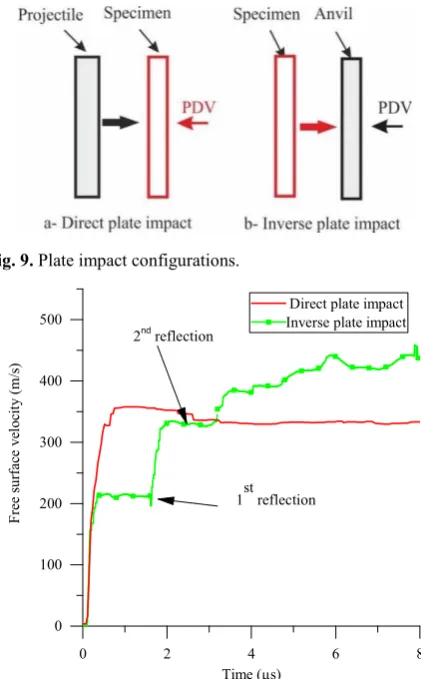
Plate impact tests are conducted to study shock wave propagation inside the material. Two configurations are tested (Figure 9a and b): a direct impact in which the specimen is impacted by a plate with well-defined EOS and an inverse impact in which the specimen is the projectile. A PDV is used to measure the material velocity at the free surface. For all tests, the impact face is normal to the third direction of the composite, therefore it is only the shock propagation in the o-o-p direction which is studied. The response in the fibre direction can be different due to the orthotropy of the material. This is at the origin of the main difficulty in conducting this test. Since wave propagates at a higher speed in the fibre direction, radial release waves rapidly reach the centre of the specimen and effects the measurement.
Typical curves are similar to the ones presented in
curves of direct plate impact. It is the case for all the curves and no spalling deformation is observed on the recovered specimens though the plies can be easily peeled. The analysis of all the data has led to the definition of the EOS of the material shown in Figure 11. The direct plate impact tests are reproduced in a FE model using a Mie-Grüneisen EOS couple with a low strength homogeneous material defined with MAT124 of LS-DYNA. The comparison of the curves is shown in Figure 12. Good correlation is obtained with the experimental data. The use of a very low tensile strength enables to prevent spalling at the back face of the specimen.
Fig. 9. Plate impact configurations.
0 2 4 6 8
0 100 200 300 400 500
Fr
ee s
ur
fa
ce
v
el
oci
ty
(m
/s)
Time (µs)
Direct plate impact Inverse plate impact
1st reflection
2nd reflection
Fig. 10. Free surface velocity obtained from plate impact tests.
clamped Sheared
0.0 0.2 0.4 0.6 0.8 1.0 0.5
1.0 1.5 2.0 2.5
N
orm
al
ized
sh
ock
sp
eed
Normalized material velocity
Fig. 11. Normalized o-o-p EOS of the composite material.
-1 0 1 2 3 4 5
0 50 100 150 200 250 300 350 400
Fr
ee
su
rf
ace v
el
oc
ity
(m
/s
)
Time (µs) Imp-1
Imp-2 Imp-3 ImpSim-1 ImpSim-2 ImpSim-3
Fig. 12. Comparison of experimental and numerical free surface velocity of direct plate impact tests.
3 Ballistic impact response
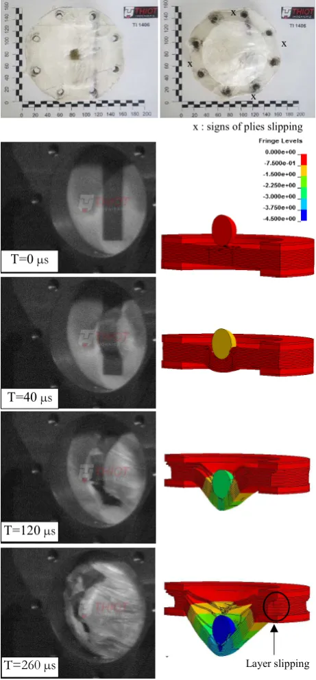
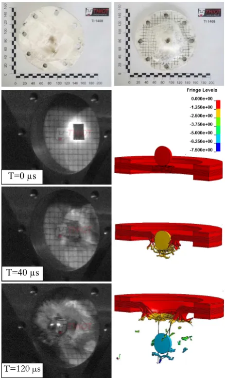
The study of the material is completed with ballistic impact tests. The test configuration is presented in Figure 13. A spherical steel projectile of 25 mm is launched with a gas gun. The target, a disk of 150 mm of diameter is clamped around its edge. The back face of the target is monitored with a PDV system to measure the velocity and a high-speed camera through a mirror. Two tests are performed with different target thickness in order to obtain non-perforated TI1406 (Figure 14) and perforated TI1408 cases (Figure 15).
For TI1406 specimen, one third of the plies from the front side are perforated. The projectile is recovered in between plies after impact. Important ply interface delamination is observed on the perforated plies.
Fig. 13. Ballistic tests configuration.
T=0 s
T=40 s
T=120 s
T=260 s
x
x x x
x : signs of plies slipping
Fig. 15. Perforated ballistic impact test (TI1408), simulation shows the o-o-p displacement in cm.
Around the impact point, the nature of the polymer has also changed as if it has been heated close to its melting point. The camera images show that the target undergoes an important back face deformation. Post-mortem analysis of the recovered target shows that non-failed plies undergo large slipping which explains the non-round shape of the specimen edge after the test.
For TI1408 test, apart from reducing the specimen thickness, it is also conducted at a higher projectile velocity. The target is completely perforated. Its deformation is not as important as TI1406 however similar signs of temperature increase is found around plies failure.
Considering all the information gathered throughout the characterization tests and the ballistic impact, a FE model of the ballistic test is realized in LS-DYNA (Figure 16). The target is modelled in 3D at a
pseudo-perforation of both ballistic cases with a little decrease in the projectile speed. The target does not have time to deform before it is perforated.
Fig. 16. FE model for ballistic impact.
400 450 500 550
0.00 0.25 0.50 0.75 1.00 1.25
Ba
ck
fac
e v
el
oci
ty
(m
/s
)
Time (µs)
TI1408 TestProjectile SimuTI1408 SimuProjectile
Fig. 17. Experimental and numerical comparison of the back-face velocity of the target and projectile residual velocity for TI1408.
To improve the simulation results, a damage model is added to the material model using MAT221in LS-DYNA. The parameter for damage evolution is set to reproduce the results of TI1408. This modification is motivated to account for the softening due to temperature increase before ply failure. The comparison of obtained back face velocity and projectile residual velocity with the experimental data is shown in Figure 17. The cinematics (Figure 15) of the deformation and perforation is also coherent with the test. The target is perforated before important ply slipping. This model is then used to simulate TI1406 test and results in a T=0 µs
T=40 µs
4 Conclusion
In conclusion, this paper has presented a detailed characterisation study of UHMWPE composite material for shock and dynamic applications combining experimental and numerical tools. Four types of characterisation tests have been conducted: in-plane tension, out-of-plane shear, compressive responses and wave propagation. The plate mechanical response is between dry fabric and thermoplastic UD composite. UD fibre provides it with good tensile strength but the matrix low shear strength makes it prone to delamination, peeling and fibre slipping. The design and analysis of the characterisation tests have been driven by such specificity in order to acquire enough data for the building of the ballistic model. The ballistic tests have highlighted the importance of ply slipping and temperature increase in the perforation mode of the plate. The simulation approach developed in this study shows interesting results for the modelling of ballistic response of UHMWPE. The modelling scale choice represents a good compromise between calculation time and reproduction of main physical phenomena. This study should be pursued on a more detailed investigation of the failure mode of material at high temperature to confirm the modelling assumptions regarding fiber damage evolution. Another important aspect would also be the investigation of friction in ply slipping.
This research was done with the financial support of the DGA Land Systems, French MoD The authors would like to thank all the team of THIOT-INGENIERIE laboratory for performing all the tests of this study.
References
1. L. Govaert, P.J. Lenstra,Colloid Polym Sci. 270 455 (1992)
2. P.J. Hazell, G.J. Appleby-thomas, X. Trinquant and D.J. Chapman, J. Applied Phys., 110 (2011)
3. J.P. Attwood, S.N. Khaderi, K. Karthikeyan, N.A. Fleck, M.R. O’Masta, H.N.G. Wadley, V.S. Deshpande, J. Mech. Phy. Solids, 70 200 (2014) 4. T. Lässig, F. Bagusat, M. May, S. Hiermaier, Int. J.
Impact Eng., 86 240 (2015)
5. M.R. O’Masta, B.G. Compton, E.A. Gamble, F.W. Zok, V.S. Deshpande and H.N.G. Wadley, Int. J. Imp. Eng. 86 131 (2015)