A Miniaturized Multiband CPW-Fed
Microstrip Antenna with Modified Ground
Structure for Wireless Applications
Neelam Sharma, Ramanjeet Singh,
Student, Dept. of ECE, Ludhiana College of Engineering and Technology, Ludhiana, India
Assistant Professor, Dept. of ECE, Ludhiana College of Engineering and Technology, Ludhiana, India
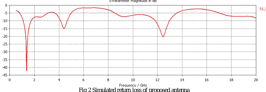
ABSTRACT: In this paper, a CPW-fed Microstrip antenna is proposed with modified ground structure for various wireless applications. The rectangular patch has four symmetrical circular slots in the patch for improved antenna characteristics. The proposed antenna has been designed with miniaturized dimensions of 30x 38x 0.7 mm3 , using Rogers RT5880 substrate. It is a multiband antenna radiating at different frequencies wit bandwidth of 0.65 GHz (1.08 GHz-1.74 GHz), 0.54 GHz (4.12 GHz-4.66 GHz) and 1.18 GHz (11.80 GHz-12.98 GHz). The VSWR is calculated to be less than 2 throughout the bandwidth and the return loss upto -42.289 dB has been obtained. The antenna is designed and analyzed using CST Microwave Studio software through which all the important antenna parameters like VSWR, gain, return loss, radiation pattern are discussed.
KEYWORDS: CST Microwave studio, Coplanar waveguide (CPW), Multiband antenna, Modified ground structure (MGS)
.
I. INTRODUCTION
In the present era of wireless communication, there is a rising need for compact size antennas with improved radiation characteristics and enhanced bandwidth. The Microstrip antennas are nowadays used for various wireless applications like WLAN, Wi-MAX and RFID as it exhibits wider bandwidth, lower radiation loss, ease of fabrication, lighter in weight, low cost and smaller in dimension. In order to achieve these results different kinds of feeding techniques are used. However the results show that out of all the conventional feeding techniques CPW feeding technique proved to be most promising. The CPW structure has resulted in ease of fabrication of patch and ground both on same plane (MGS) for reduced complexity [1].
A CPW-fed antenna [2] with operating bandwidth of 2.6 to 13.04 GHz is presented for UWB applications. A Microstrip antenna protruded with pair of L-strips and inverted L-strips on either side resonating at 3.6 GHz and 8.1 GHz for Wi-Fi applications is formed using CPW feeding technique [3]. The ground is modified to form two UWB antennas radiating across 2.9-11.5 GHz and 2.9-11.89 GHz respectively [4].
is observed that by cutting slots in the patch of Microstrip antennas the bandwidth can be enhanced [5]. The multiple slots can increase the bandwidth of an antenna up to 70.8%without affecting resonant frequency, and radiation pattern [6].A multiple circular slots Microstrip antenna is formed which works in four frequency bands applicable in C-band, X-band, Ku-band and K-band [7].
A trapezoidal CPW fed antenna shows omnidirectional radiation pattern across the whole bandwidth of 2.3-9.7 GHz [8] applicable in ultra wideband applications. An antenna is formed with 56 similar radius circular slots for operation in ISM band [9]. A rectangular patch [10] with two symmetrical steps like slots modifies the patch to give omnidirectional radiation pattern and ultra bandwidth region.
II. ANTENNA DESIGN
The geometrical specifications of the proposed antenna for multiband applications are illustrated in figure 1. The given antenna is made of Rogers RT5880 substrate with permittivity 4.4. The length and width of substrate are 60mm and 80mm respectively and the thickness of substrate is measured to be 0.5mm. As shown in figure 1, the radiating patch of the antenna has four symmetrical circular slots of radius (r) 3.2 each.
Fig1: Design of proposed antenna
Parame
ter Description Dimension (mm)
W Width of substrate 80
L Length of substrate 60
Wp Width of patch 38
Lp Length of patch 30
Wf Width of feed 7.8
L1 Width of ground plane 36
L2 Length of ground
plane
14.5
s Width of stub 5
h Height of substrate 0.5
W
L
Wp
Lp
L1 Wf
Fig 2 Simulated return loss of proposed antenna
Also, the proposed antenna satisfies the VSWR characteristics i.e. the VSWR throughout the resultant resonant frequencies of the multiband antenna is less than 2 as shown in figure 3.
Fig 3 VSWR plot for the proposed antenna
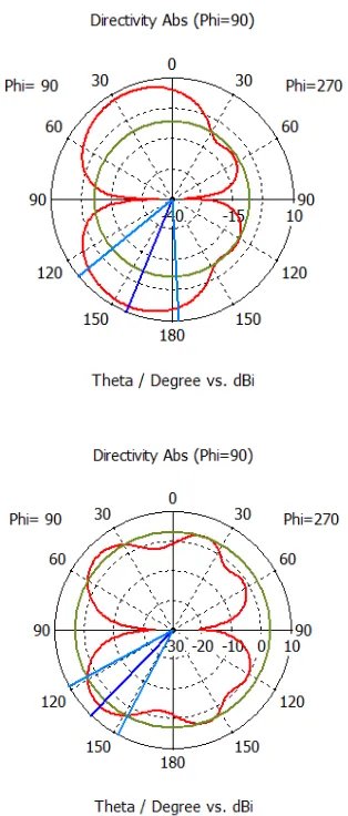
Fig 4 E-plane radiation patterns at different resonating frequencies
3. S.Chidambara Krishnan, S.A.Arunmozhi, “ Design of CPW Fed Monopole Microstrip Patch Antenna For Wi-Fi application,” 978-1-4799-3358-7114/$3l.00 ©2014 IEEE
4. Kirti Vyas, Arun K. Sharma, Promod K. Singhal, “ Design and Analysis of Two Novel CPW-Fed Dual Band-Notched UWB Antennas with Modified Ground Structures,” Progress In Electromagnetics Research C, Vol. 49, 159-170, 2014
5. Meriem Harbadji, Amel Boufrioua, “ Investigation of rectangular multi-band Microstrip patch antennas with slots,” 978-1-4799-7391-0/14/$31.00©2014 IEEE
6. Achmad Munir, Guntur Petrus, Hardi Nusantara, “ Multiple Slots Technique for Bandwidth Enhancement of Microstrip Rectangular Patch Antenna,” 978-1-4673-5785-2/13/$31.00 ©2013 IEEE
7. Md. Imran Hasan, M.A. Motin, Md. Samiul Habib, “ Circular Ringing Slotting Technique of Making Compact Microstrip Rectangular Patch Antenna for Four Band Applications,” 978-1-4799-0400-6/13/$31.00 ©2013 IEEE
8. Shaowen Hu, Yiqiang Wu, Ye Zhang, Huilin Zhou, “ Design of a CPW-Fed Ultra Wide Band Antenna,” Open Journal of Antennas and Propagation, 2013, 1, 18-22
9. Waqas Farooq, Masood Ur-Rehman, Qammer H. Abbasi, Khawaja Qasim Maqbool, Khalid Qaraqe, “ Study of a Microstrip Patch Antenna with Multiple Circular Slots for Portable Devices,” Proceedings of the 8th IEEE GCC Conference and Exhibition, Muscat, Oman, 1-4 February, 2015 978 − 4799 − 8422 − 0/15/$31.00c 2015 IEEE