Review of ZigBee based Communication
System Design for Future Micro Grids
Pranav Bhalerao
M.E. Student, Dept. of E&TC., SPCOE, Savitribai Phule Pune University, Pune, India
ABSTRACT: A communication system for micro grids (MGs) is presented in this project using NS2. It is assumed that each MG consists of one central controller and multiple distributed generation units with respective local controllers. The communication system is designed for transmitting and receiving data amongst these controllers and the end sensors or actuators. This communication system will prove useful with low cost and low power consumption devices like ZigBee. However, ZigBee has low data transfer rate. Hence the proposed system is designed to filter out redundant data using duplicate acknowledgements and it also utilizes a data management scheme which reduces overall data transfer rate requirement. The communication system can smartly route the data between the nodes in case of failure of a path or device. Finally, I have also plotted the output of PDR, throughput and end to end communication time.
KEYWORDS: Communication system, data management scheme, micro grids (MGs), ZigBee, NS2
I. INTRODUCTION
Current energy distribution grid has been in use for almost a century. The aging of equipment and increasing consumer demands necessitate a revolution in the grid. By 2020, it is foreseen that the energy demand will almost be double the present demand. Recently, North American and European governments have been investing largely on smart grid technologies to change the way the energy is produced, distributed and consumed.
The number of renewable energy resources like solar, wind and micro-hydro are growing significantly in the form of distributed generation (DG) units over past decade. Integration of these units in electric network will have several benefits such as reduced network expansion cost, minimized power loss, increased reliability and faster recovery of faults [1]. A Micro grid is a geographically bound part of smart grid with clusters of distributed generation units and loads. The micro grid has two modes of operations: autonomous mode and grid-connected mode. In grid connected mode, the central controller dictates the network voltage and frequency. The mode of operation is controlled by circuit breaker.
A micro grid will be fully automated in near future [2]. This will include collecting data from sensors and sending it to the central controller and finally passing the action commands to the actuators. Hence a fast, reliable and accurate communication system is must to transfer the data between respective controllers. ZigBee based communication system is ideal for this purpose.
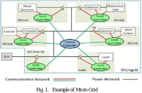
Micro grid (MG) is a cluster of loads, DGs and energy storages interconnected by a network of feeders and located in the same geographical area. It can act as an independent power system whenever needed. In the presence of a utility grid, an MG can operate either in grid-connected mode or in autonomous mode. In grid-connected mode, the network voltage and frequency are dictated by the grid; hence the DGs are controlled such that the desired amount of power (based on maximum power point tracking or economic power dispatch) is supplied by each DG.In autonomous mode, the DGs are not only required to supply the MG load demand but should also regulate the feeder voltage and frequency within acceptable limits. Therefore, for proper operation and control of DGs within an MG, each DG should be updated with the information about the MG operating mode. This information is required to be transferred from the MG main circuit breaker (CB) that connects the MG and the grid to all the DGs
transfer the action controls to the local controller if any action is needed. Central Controller will also provide the status of circuit breaker to each local controller.
Fig. 1. Example of Micro Grid
II. COMMUNICATION TECHNOLOGIES
We can use both wired and wireless technologies in MGs. Popular wired technologies are serial communication RS 232/422/485, power line communication, bus technology and Ethernet. On the other hand, popular wireless technologies are Wi-Fi, WiMax, ZigBee, cellular, radio frequency and microwave [3].
Wired technologies are more reliable and have higher data bandwidth however they add to already complex grid network and have costlier installation process. Wireless technologies are comparatively cheaper and suitable for remote location. They can also easily accommodate any future expansion needs.
The cost of implementing a wired technology will be significantly high with every increasing number of meters, sensors and actuators. Hence, wireless technology is best suited for the purpose of MG applications even though they have lower data transmission rates [4].
The delay of the communication system is very crucial in MG applications and must be kept within acceptable limits. The processing time of ZigBee is about 400 – 600 μs, for transmitting three different data. ZigBee has two communication capabilities, i.e., reduce function device (RFD) and full function device (FFD). A RFD can communicate with end nodes like sensors, meters or actuators but it cannot communicate with other RFDs. Hence it acts as an end node. FFD can communicate with other FFDs as well as the sensors, meters or actuators. Hence it acts as a router [5].
III.COMMUNICATION SYSTEM DESIGN
A. Block Diagram
The sensors, actuators and meters in the network can directly communicate with the local controller using analog to digital converters, serial communication or general purpose input output ports. The local controller can process this data and transmit it to the central controller through FFD. This is shown in Fig. 2(a).
Fig. 2. (a) DG local controller connection to MG central controller. (b) CB status and voltage/frequency data transfer to central controller through RFD.
The connection between the end nodes like sensors, meters and actuators to the local controller is wired wherein local controller communicates to the central controller through a ZigBee FFD wireless node. The RFDs are known as reduced functionality devices and can only connect to end nodes, whereas the fully functional devices can also connect to other FFDs.
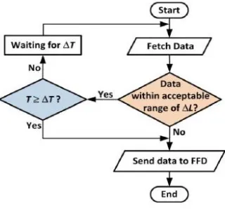
B. Communication Flow Chart
Due to huge number of end nodes involved, the micro grid communication system will have large number of data transmission. As ZigBee has limited rate of data transmission, a careful management of data flow is must such that the network bandwidth can handle the data traffic [6].
Real time data transfer is required only for the CB status. Other parameters like voltage magnitude, frequency and angle can be sent after a short interval of ∆T. This will reduce the data transmission through channel. To further reduce the data transmission, we can define acceptable limits for data variation such that the data will be transmitted only if it exceeds the defined limit ∆L. For example, data variation limit for frequency will be 49.5 to 50.5 Hz and for voltage, it will be 210 to 250 volts. Based on the interval and data variation value, the flow chart is shown in Fig. 3. Thus we can efficiently use ZigBee devices which have less data transmission bandwidth but are but are cheaper for mass use.
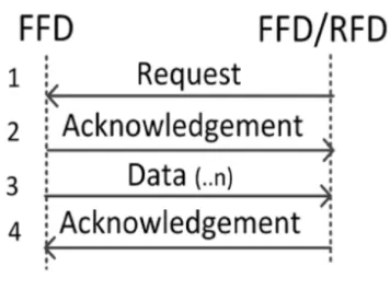
The system is designed to have a dual handshake protocol for better reliability. Fig. 4 shows the communication sequence of data transfer between RFDs and FFDs. The coordinator of FFD sends a request for data transmission to RFD/FFD. Then, the RFD / FFD confirm the request by sending an ACK signal and the requested data. Once the complete data is received, the coordinator will send an ACK signal to the respective RFD/FFD. So both the nodes will have an acknowledgement of data increasing reliability of the system. Hence by using the time interval, data variation limit and dual handshake, we can achieve both low transmission rate as well as reliability of the data.
Fig. 4. Communication sequence between RFDs and FFDs.
IV.DATA MANAGEMENT IN MGS
Number of DGs in MG changes the number of parameters, nodes and data to be monitored and maintained in MG. In addition, there might be variation of data types in different DGs, such as, some DGs might need to send data related to weather condition as well.. Consequently, the number of data to be transferred in the MG can be very large. Since the data transfer rate of ZigBee is only up to 250 kbps, the data transmission in MGs should be carefully managed such that the network bandwidth can handle the data transactions.
The data management scheme proposed in this project is based on defining a suitable time interval for transmitting the data and proper number of bits representing the data. Fig 5 shows the proposed number of bits for each data parameter in the MG.
Fig. 5. Data management scheme of the system.
The data value for each parameter can be sent in text as well as binary format. Text format is useful for human understanding and future expansion of the system. The text data first needs to be converted into ASCII code. This ASCII code is used to create a binary value of the data. This increases system overload. The binary data on the other hand can be easily coded and transmitted into the system, but it proves difficult to understand.
V. CONCLUSION
as well as the reference for voltage magnitude and angle and CB status from the central controller to the local controller of each DG unit.
ZigBee standard data frame will be utilized for transmitting the data while a new coding is presented for the data payload section of this frame. The new coding can represent each of the above-mentioned data, their values, dimensions and the origin of the data (sensor, meter, etc.) in binary or text formats. The data payload section may be composed of a fixed number of bits or a variable number of bits, as proposed.
The selection of the binary/text format, fixed/variable number of bits for the data payload, and the carrier frequency will affect the data transmission delay. A comparison will be provided on the expected data transmission delay as well as the maximum number of symbols used for the data transaction in MGs with several DG units. These analyses will be carried out for the above-mentioned data sets and the relevant transmission delays will be calculated in each format/coding configuration
From primary analyses, it can be seen that to cover a vast area, ZigBees with carrier frequency of 868 or 915 MHz are required; however, the data transmission delay is increased while for shorter distances, a 2.45 GHz ZigBee can be used which has a much smaller data transmission delay.
REFERENCES
[1] Robert H. Lasseter, Paolo Piagi, “The design space of wireless sensor networks”, in Proc. IEEE 35th Annu. Power Electron. Spec. Conf., Aachen, Germany, pp. 4285–4290, 2004.
[2] A. Sendin, “Communication and Networking in Smart Grids”, in Communication and Networking in Smart Grids, Y. Xiao, Ed. Boca Raton, FL, USA: CRC Press, pp. 241–275, 2012.
[3] Department of Energy, US government, “Smart Grid”, https://www.smartgrid.gov .
[4] Nithin.S and Dr.N.Radhika, “Smart Grid test bed based on GSM”, Procedia Eng., vol. 30, no. 2011, pp. 258–265, 2012.
[5] N. C. Batista, R. Melício, J. C. O. Matias, and J. P. S. Catalão, “Photovoltaic and wind energy systems monitoring and building/home energy management using ZigBee devices within a smart grid,” Energy, vol. 49, pp. 306–315, Jan. 2013.