High speed and Area Efficient Rounding Based Approximate Multiplier for
Digital Signal Processing
B Chandravathi1, D Nagaraju2
1M.Tech Student, Department of ECE, Vagdevi Institute of Technology and Science , Proddatur, India 1Assistant Professor, Department of ECE, Vagdevi Institute of Technology and Science , Proddatur, India
ABSTRACT
Approximate computing can decrease the design complexity with an increase in performance and power efficiency for error resilient applications. This brief deals with a new design approach for approximation of multipliers. Energy consumption is one of the key factors for various processing application like DSP, ASIC and FPGA. The main aim of this project is to approximate the multiplying operation. The approach is to round the operands to the nearest exponent of two. Through this way the speed is increased and energy consumption is reduced by reducing computational operations at the price of a small error. In this way, the computational intensive part of the multiplication was omitted improving speed and energy consumption at the price of a small error. The proposed approach was applicable to both signed and unsigned multiplications. Three hardware implementations of the approximate multiplier including one for the unsigned and two for the signed operations were discussed. The proposed 8-bit RoBA multiplier for signed and unsigned multiplication offers better efficiency in energy consumption .Furthermore, the area is compacted well besides it provides reduction in Power Delay Area (PDA).
Keywords : Round-off, Approximate, Energy consumption Rounding Based Approximate Multiplier (RoBA), Power Delay Product (PDA).
I.
INTRODUCTIONEnergy minimization is one of the main design requirements in almost any electronic systems, especially the portable ones such as smart phones, tablets, and different gadgets. It is highly desired to achieve this minimization with minimal performance (speed) penalty. Digital signal processing (DSP) blocks are key components of these portable devices for realizing various multimedia. Applications. The computational core of these blocks is the arithmetic logic unit where the multiplications and additions are the major part. The multiplications play the high percentage of operation in the processing elements which can leads to high energy and power
consumption. The power and energy efficiency plays major role in processor effectiveness.
advantage of this proposed architecture reduces the error rate and gain high speed.
In this paper, we focus on proposing a high-speed low power/ energy yet approximate multiplier appropriate for error resilient DSP applications. The proposed approximate multiplier, which is also area efficient, is constructed by modifying the conventional multiplication approach at the algorithm level assuming rounded input values. We call this rounding-based approximate (RoBA) multiplier. The proposed multiplication approach is applicable to both signed and unsigned multiplications for which three optimized architectures are presented. The efficiencies of these structures are assessed by comparing the delays, power and energy consumptions, energy-delay products (EDPs), and areas with those of some approximate and accurate (exact) multipliers. The contributions of this paper can be summarized as follows:
1) Presenting a new scheme for RoBA
multiplication by modifying the conventional multiplication approach;
2) Describing three hardware architectures of the proposed approximate multiplication scheme for sign and unsigned operations.
The architectures for both accurate and approximate calculations are performed by eliminating some of the steps without affecting the expected output with the help of this method. The main objective of this project is to achieve an energy minimization, error rate reduction, low power and high speed by reducing the number of shifting and adding operations. For correcting the division error compare operation and a memory look up is required for the each operand is required which increases the overall time delay.
Broken Array Multiplier (BAM) was proposed for efficient VLSI implementation of soft computing
application [2]. The mean and variance of the errors of the imprecise model increase by only 0.63% and 0.86% with respect to the precise WPA and the maximum error increases by 4%. The inaccurate multipliers achieve an average power saving of 31.78% − 45.4% over corresponding accurate multiplier designs, for an average error of 1.39%−3.32%. Low-Power DSP uses approximate adders which are employed in various signal processing algorithms and architectures. When compared with standard multiplier, the power dissipation of the ETM dropped from 75% to 90%. While maintaining the lower The multiplication of A by B may be written as
( ) ( ) ( ) ( ) ( ) ( )
Key observation is that the multiplications of , and may be implemented just by the shift operation which is shown in the eqn (1).
To perform the multiplication process, the following expression is used
(( ) ( )) ( ) ( )
Thus, one can perform the multiplication operation using three shift and two addition/subtraction operations. In this approach, the nearest values for A
and B in the form of 2n should be determined. When the value of A (or B) is equal to the (where p is an arbitrary positive integer larger than one), it has two nearest values in the form of2n with equal absolute differences that are 2p and 2p−1. While both values lead to the same effect on the accuracy of the proposed multiplier, selecting the larger one (except for the case of p = 2) leads to a smaller hardware implementation for determining the nearest rounded value, and hence, it is considered in this paper. It originates from the fact that the numbers in the form of are considered as do not care in both rounding up and down simplifying the process, and smaller logic expressions may be achieved if they are used in the rounding up.
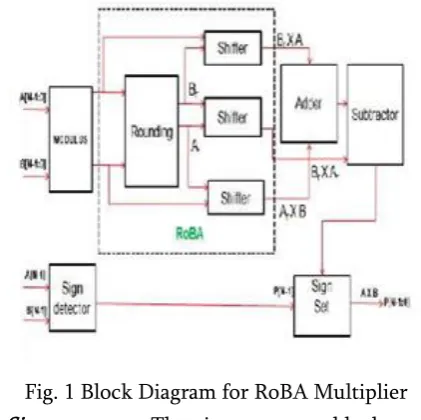
Fig. 1 Block Diagram for RoBA Multiplier
1) Sign extractor: The sign extractor block extracts the sign of the input values and gives as output their absolute value. It detects the sign bit (most
significant bit) of the input represented in two’s complement format. Then, it reverses the input in the case of negative values, and keeps it unchanged for the positive ones
2) Round/ shift: This block applies the rounding on the absolute values to find the nearest values of the inputs. Therefore, the output values are extracted in the form of 2 n following the rounding process. Along the process, each rounded bit could be equal to one in the following cases: When the two right-side bits of the input bit M[i] are one, M[i] and all the bits on its left-side are zero. When the right side bit of M[i] and all its left-side bits are zero while M[i] is one. Since the rounded values are represented in the form of 2n, the products are simply obtained through a barrel shifter. The products of n bit width are shifted based on or depending on the operand M or N respectively. The output bit widths generated from the shifter block are 2n.
3) Brent kung Adder:
The Brent Kung adder computes the prefixes for 2 bit groups. These prefixes are used to find the prefixes for the 4 bit groups, which in turn are used to compute the prefixes for 8 bit groups and so on. These prefixes are then used to compute the carry out of the particular bit stage. These carries will be used along with the Group Propagate of the next stage to compute the Sum bit of that stage. Brent Kung Tree will be using 2log2N - 1 stage. Since we are designing a 32-bit adder the number of stages will be 9. The fan out for each bit stage is limited to 2. The diagram below shows the fan out being minimized and the loading on the further stages being reduced. But while actually implemented the buffers are generally omitted.
The entire BKA is a process divided into the following three stages:
2. Carry generation network 3. Post-processing
During Pre-processing stage, the generate and propagate signals corresponding to each pair of bits from the inputs A and B are obtained. Mathematically, this may be defined as
Where Pi and Gi are the propagate and generate for ith input and Ai and Bi are the inputs for the ith stage. During the next stage, carries corresponding to each bit is computed using the carry generation network. This network consists of two fundamental elements called as Grey cell and Black cell. The grey cell computes the carry output of the current stage based on all previous carried directly, while the black cell computes both generate and propagate based on previous inputs. The generation operation is carried out in parallel and therefore accounts for the high processing speed of this adder. The functioning of this adder may be explained by the following set of equations:
( ) ( ) ( )
( ) ( ) ( ( ) ( ))
The Generate Gi:j is generated by the grey cell. While the Propagate Pi:j is generated by the black cell along with the generate block for the same stage. The structure of the propagate and generate, black cell and the grey cell are as shown in Figures below respectively. After obtaining final generate signal, sum is obtained by performing XOR operation between propagate signal from PG block and generate signal from each grey cell.
Figure2 - Structure of Black Cell for the implementation of KSA
Figure3- Structure of Grey Cell for the implementation of KSA
Figure4 – Brent Kung Adder
4) Sign set: The main function of the sign set block is to set the sign of the final multiplication result. It reverses the output of the subtractor when the extracted sign (from sign extractor) for the two input values is different.
III.
Structure Level Design Of ROBA Multiplierrounding criteria discussed in the upcoming chapter. There are four cases for selecting the values of the final rounded of value from the original input values there are discussed below
a. In this case the value of Ar is high and the value of Br is low.
b. In this case the value of Ar is low and the value of Br is high.
c. In this case the value of Ar is high and the value of Br is high.
d. In this case the value of Ar is low and the value of Br is low.
By selecting the case one, the approximate result is higher than the exact result. From the case two and three, the approximate result is slightly higher than the accurate result when compared with the case one. For case four, the approximate result is lower than the exact result. The program should be slightly modified for each one of the case. The error rate is very low when case one and four are considered when compared with other two cases. The error rate is also one of the important factors that should be considered while designing the approximate multiplier. The mean error distance is calculated before calculating the error rate of the proposed rounding based approximate multiplier. In this paper, if the negation is performed exactly (approximately), the implementation is called signed RoBA (S-RoBA) multiplier [approximate S-RoBA (AS-RoBA) multiplier]. In the case where the inputs are always positive, to increase the speed and reduce the power consumption, the sign detector and sign set blocks are omitted from the architecture, providing us with the architecture called unsigned RoBA (U-RoBA) multiplier.
IV.
Results and DiscussionsIn this section, inaccuracies of the three architectures discussed above are considered. The inaccuracies of
the U-RoBA multiplier and S-RoBA multiplier, which originate from omitting the term ( ) ( ) from the accurate multiplication of A × B, are the same. Assuming Arand Br are equal to 2n and 2m, respectively, the maximum error occurs when A and B are equal to 3x 2n and 3 x 2m, respectively. Hence the error rate for signed approximate RoBA multiplier is given in the eqn (3).
In this case, both Ar and Br have the maximum arithmetic difference from their corresponding inputs rounding which is equal to and 2m, respectively and their maximum error rate is given in the eqn (4).
In this case of the AS-RoBA multiplier, the error includes an additional term due to approximate Negation. Therefore, in the worst case (where both inputs are negative), one may obtain the maximum Error from the eqn (5).
Compared with above equation the second term comes from the negation approximation obtained from the following relation: Therefore the eqn (6)
when one of the inputs is −1, the maximum error, which is 100%, occurs. Finally, in the case of the AS-RoBA multiplier, as mentioned before, the maximum error happens when one of the
Comparison of area and delay between three architectures of ROBA multiplier
Multipliers Area in
LUTS
delay
Signed ROBA 218 25.08ns
Unsigned
ROBA 200 15.532ns
Approximate S
ROBA 120 11.918ns
Table1. Three architecture comparisons
Comparisons between ROBA with kogge stone adder and ROBA with less area Brent Kung adder
ROBA with KS adder
ROBA with BK adder
AREA 265 218
DELAY 20.183ns 25.08ns
Table 2. Comparisons between ROBA
Block Diagram
Schematic Diagram
Simulation Result
V.
Conclusion And Future ScopeVI.
REFERENCES[1]. Mitchell, J. N. (1962). Computer multiplication and division using binary logarithms. IRE Trans. Electron. Comput. EC-11: 512–517. [2]. H. R. Mahdiani, A. Ahmadi, S. M. Fakhraie,
and C. Lucas, “Bio-inspired imprecise computational blocks for efficient VLSI
implementation of soft-computing
applications,” IEEE Trans. Circuits Syst. I, Reg. Papers, vol. 57, no. 4, pp. 850– 862, Apr. 2010 [3]. R. Venkatesan, A. Agarwal, K. Roy, and
A.Raghunathan, “MACACO: Modeling and analysis of circuits for approximate computing,” in Proc. Int. Conf. Comput.-Aided Design, Nov. 2011, pp. 667– 673.
[4]. F. Farshchi, M. S. Abrishami, and S. M. Fakhraie, “New approximate multiplier for low power digital signal processing,” in Proc. 17th Int. Symp. Comput. Archit. Digit. Syst. (CADS), Oct. 2013, pp. 25–30.
[5]. P. Kulkarni, P. Gupta, and M. Ercegovac, “Trading accuracy for power with an under designed multiplier architecture,” in Proc. 24th Int. Conf. VLSI Design, Jan. 2011, pp. 346–351. [6]. V. Gupta, D. Mohapatra, A. Raghunathan, and
K.Roy, “Low- power digital signal processing using approximate adders,” IEEE Trans. Comput.-Aided Design Integr. Circuits Syst., vol. 32, no. 1, pp. 124– 137, Jan. 2013.
[7]. M. Alioto, “Ultra-low power VLSI circuit design demystified and explained: A tutorial,” IEEE Trans. Circuits Syst. I, Reg. Papers, vol. 59, no. 1, pp. 3–29, Jan. 2012.
[8]. K.Y. Kyaw, W. L. Goh, and K. S. Yeo, “Low-power high-speed multiplier for error tolerant application,” in Proc. IEEE Int. Conf. Electron Devices Solid-State Circuits (EDSSC), Dec. 2010, pp. 1–4.
[9]. A.B. Kahng and S. Kang, “Accuracy-configurable adder for approximate arithmetic
designs,” in Proc. 49th Design Autom. Conf. (DAC), Jun. 2012, pp. 820–825.
[10]. Samir Palnitkar, Verilog HDL: A Guide to Digital Design and Synthesis, Second edition, Prentice-hall PTR, 2003.