Super Twisting Algorithm Direct Power Control of
DFIG using Space Vector Modulation
Farida. Mazouz*, Sebti. Belkacem,*LEB, Department of Electrical Engineering, University Mostefa Ben Boulaid Batna-2 Algeria *[email protected],
s.
[email protected]Abstract:
This paper presents the super-twisting algorithm (STA) direct power control (DPC) scheme for the control of active and reactive powers of grid-connected DFIG. Simulations of 5 KW DFIG has been presented to validate the effectiveness and robustness of the proposed approach in the presence of uncertainties with respect to vector control (VC). The proposed controller schemes with fixed gains are effective in reducing the ripple of active and reactive powers, effectively suppress sliding-mode chattering and the effects of parametric uncertainties not affecting system performance.Keywords: DFIG , SVM, VC, 2-SMC, STA, Wind Turbine (WT), parameters uncertainly.
1. Introduction
In recent years and with its economic and environmental benefits, wind energy has become more and more a source of energy for many countries, in addition, and because of its advantages, the dual feed induction generator (DFIG) is currently the generator of choice for driven wind turbines [1-8].
The vector control (VC) using conventional proportional-integral (PI) controllers allowsdecoupled control of the active and reactive powers typically applied for their simplicity [9-10]. However, the
VC structure strongly count on the parameters of the machine and require exact knowleduses of the system model, therefore can not ensure the robustness of the system in the face of parameter
variations and model uncertainties. Different strategies have been presented in the literature to remedy the aforementioned difficulties. Direct torque control (DTC) or direct power control (DPC) has been introduced in [11-12]. The application of DPC on the DFIG had many advantages over the classical VC method: no coordinate transformations, no current loops, less dependence on
parameters. From its basic version the classical direct power control causes fluctuations in the currents, the reactive, active powers and the variable switching frequency because of the use of
hysteresis regulators. Several approaches are suggested on the development of DPC techniques operating at a constant switching frequency. using space vector modulation [13-16]. its precaution is
elimination of the hysteresis regulators and the switching table. The reduction of the power pulsation and the quality of the power has been achieved. These controllers are not robust to
uncertain parameters.
The authors suggested the application of DPC in a DFIG-based wind turbine system under
unbalanced grid voltage conditions [17-18]. The control strategy consists of a purely sinusoidal and
balanced stator and GSC current injector, without the need to extract the negative sequence
harmonics. The dual frequency pulses of the reactive power of the stator and the torque are
completely eliminated when the torque / power is changed in transient and transient conditions
when the voltage is unstable.
Several model predictive direct power control (MP-DPC) techniques were proposed in [19-20].
Its advantages over conventional control techniques such as multivariate control do not require
phase locked loops (PLLs) or the removal of cascading control loops, good reference tracking to
grid parameter variations. The drawback of the MPC command takes a long time for execution, so
the method finds its application much more in slow systems with large sampling period where the
application of numerical methods does not pose a problem. For fast sampled high frequency
systems such as motors, robots ..., the online digital solution of the optimization problem may be
impractical. Also, it is useful to look for quick and effective solutions.
Sliding mode control (SMC) is an effective control strategy that has been well developed in the literature because of its simplicity, robustness to parameter variations and external disturbances.
This algorithm has already been suggested in different applications [21-23]. The combination of this algorithm and DPC improves power responses. The disadvantage of this combination is that the use of the discontinuous function introduces a static error, high frequency oscillations due to chattering phenomena, this phenomenon is the major disadvantage of hits practical implementation. In
literature a lot of work to suppresses chattering, for example, replacing the discontinuous saturation control function. This technique was one of the classical techniques used to reduce ripples. Although
this method reduces chattering but the controller becomes continuous and the SMC characteristics, such as convergence and robustness, can not be achieved and steady-state errors can also occur.
Another technique is to use a second-order or higher sliding-mode command, such as super-twisting , which combines a MPPT using a fuzzy logic algorithm [24]. In [25-28], the authors
propose controllers in second order sliding control.
The purpose of this paper is to use a second order continuous sliding mode control for a DFIG drive, this control strategy presents attractive features such as robustness to parametric uncertainties and attenuate chattering. The proposed strategy is compared with vector control.
2. WIND TURBINE MODELING
The relationship between the wind power and wind speed by the rotor blade of a wind turbine can be expressed as:
3 1
. . . 2 v
P = S v (1)
The mechanical power expression as [30]:
3 1
. . ( , ). . . 2
aer p v p
P =C P = C S v (2)
The tip speed ratio is described by:
. turbine
R v
= (3)
3 1 1 ( , ). . . . . 2 aer aer p turbine turbine P
T = =C S v
(4)
2 turbine g J J J G
= + (5)
The dynamic equation can be written as follows [31]:
. turbine .
g em mec
d
T T J f
dt
− = + (6)
3. MODELING OF THE DFIG
In the synchronous repository (d-q) we can highlight the DFIG dynamic equations as follows[4]:
ds
ds s ds s qs
qs
qs s qs s ds
dr
dr r dr r qr
qr
qr r qr r dr
d
V R I
dt d
V R I
dt d
V R I
dt d
V R I
dt = + − = + + = + − = + + (7)
The flux equations are given by:
ds s ds dr
qs s qs qr
dr r dr ds
qr r qr qs
L I MI
L I MI
L I MI
L I MI
= + = + = + = + (8)
We present the torque equation as follows:
( )
em qr ds dr qs
s M
T p I I
L
= − (9)
We define the supplied active and reactive powers as:
( )
( )
s ds ds qs qs
s qs ds ds qs
P V I V I
Q V I V I
= +
= − (10)
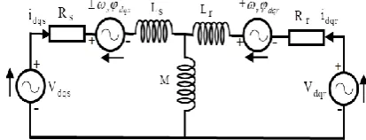
The Figure 1. represented the equivalent circuit of a DFIG expressed in the synchronous rotating
reference frame.
Figure 1. Equivalent circuit of a DFIG in synchronous rotating reference frame.
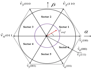
Three phase voltage-fed PWM inverters are shown in Figure 2. Sector 1 Sector 2 Sector 3 Sector 4 Sector 5 Sector 6
(100) 1 Vr V sref r (000) 0 Vr (111) 7 V r (101) 6 Vr (001) 5 Vr (011) 4 Vr (010) 3Vr Vr2(110)
Figure 2. Model of SVM techniques for inverter.
Each voltage vector in every sector, is composed by basic space voltage vector of the two side of sector and one zero vector. For example, in the first sector, we have a compound spatial vector
expressed by [13]:
s ref s 0 0 1 1 2 2
V T = V T + V T + V T (11)
With: T = T + T + Ts 0 1 2
Where, T0,T1andT2 is the working time of basic space voltage vectors.
PRINCIPAL OF VECTOR CONTROL APPLIED TO THE DFIG
The vector control based on the stator flux orientation makes it possible to independently control the active and reactive powers by the rotor side converter (RSC). The currents are controlled
by two PI correctors which determine the references of the voltages to be applied (Vrd, Vrq).
The objective of VC is consists in maintain φ = 0 , and φ = φqs ds s. wheresrepresent the reference
flux. By remplasing the principle of vector control, the electromagnetique torque is presented as:
( )
em qr s
s M
T p I
L
= (12)
The rotor voltages expression according to the rotor currents are obtained by the organization of the equations (7) and (8) by:
2 2
2 2
(L ) (L )
(L ) (L )
dr
dr r dr r s r qr
s s
qr s
qr r qr r s r dr
s s s
dI
M M
V R I g w I
L dt L
dI M V
M M
V R I g w I g
L dt L L
= + − − −
= + − − − +
(13)
Negligible stator resistance Rs and the stator flux is constant oriented along the axis, we can deduct
from equation (7):
0
s ds
qs s s qs
d V dt V V = =
We can be expressed the active and reactive powers with the rotor currents as follows:
( )
s s qr
s
M
P V I
L
= − (15)
2
( s )
s s dr
s s s
V M
Q V I
L w L
= − (16)
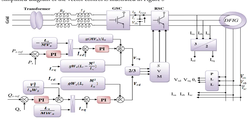
The simplified diagram of the vector control is illustrated in Figure 3
Grid DFIG
Transformer GSC RSC
Ps-ref
Qs-ref
Ps
Qs
Ira Irb Irc
PI
2/3 PI
PI
PI
3 2
Ird Irq
P L L
Vsd Vsq θs
Isa Isb Isc V
M
S
Figure 3. Vector control of DFIG.
DESIGN OF SECOND ORDRE SLIDING MODE CONTROL OF DFIG
The purpose of the SMC is to converge the system state trajectories to a predefined sliding variety.
The controller causes unwanted high frequency ripples. The second order sliding mode control is useful for reducing "chattering" as it applies to the second derivative of the system. This section
introduces the Super Twisting algorithm. In order to reduce the chattering phenomenon, and maintaining the properties of robustness and convergence of the system in finite time. In this control,
the sliding surfaces are chosen so as to be compatible with the errors in the powers of the stator.
6. 1.Super Twisting Algorithm
The (STA) among the most popular second-order sliding mode algorithms. This algorithm only
applies to systems of relative degree 1. Its interest lies in the reduction of chattering, due to the continuity of the control signal. This command breaks down into an algebraic and integral term. We
can therefore consider this algorithm as a nonlinear generalization of a PI [25]. The Super-Twisting algorithm, like other algorithms of the same categorical, requires only the information on S and
causes the cancellation of that one in a finite time; it also makes it possible to construct a differentiator called generally an exact differentiator [26]. The command law of fuper-twisting is
1 2
u= −s sign(s)−
sign(s).dt (17)where 𝛼 and 𝛽 are positive bounded constants.
The controller gains 𝛼 and 𝛽 should be over-estimated respecting to the system bounds with
uncertainty in order to get a robust controller, as given in [28].
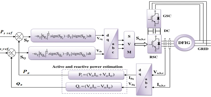
Figure 4 illustrates the proposed 2-SMC-SVM scheme for controlling active and reactive powers.
GRID DFIG RSC S V M GSC DC Sa,b,c Vrq Vdr Va,b,c Ia,b,c Idq Vdq
Active and reactive power estimation d q a b c d q a b c SP SQ 1 2
s s s
P P P
1. S .sign(S ) 1.sign(S ).dt
− −
1 2
s s s
1. SQ .sign(SQ) 1.sign(SQ).dt
− −
s qsds ds qs
Q =(V I −V I )
s ds ds qs qs
P =(V I +V I )
Figure 4. Block diagram of the control structure by 2- SMC. 7. SIMULATION RESULTS
In order to validate the results obtained through the different approaches, it is necessary to make
a comparison of the static and dynamic characteristics of the two control techniques under the same operating conditions and in the same simulation configuration. Simulation studies of the
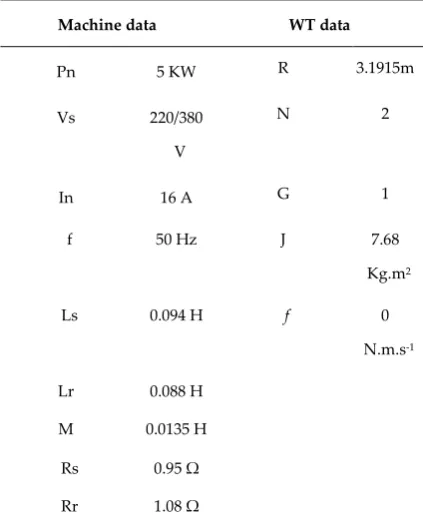
DFIG-based training system were performed using MATLAB / Simulink. The parameters of a wind turbine and a DFIG are presented in Table.2.
7. 1.Simulation Results Without Parametric Variation
A. Simulation Results With Constant Speed
Simulations involving vector control and second order sliding mode control schemes. DFIG is used
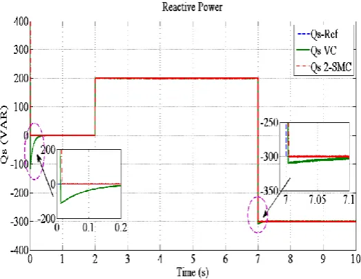
in a constant speed mode. Figures 5 and 6 compare the responses of the system during different active and reactive power steps for the two schemes, respectively. As these figures show, the
robustness of the proposed controller scheme is also confirmed in terms of tracking aptitude compared to VC.
Figure 5. Active power response.
Figure 6. Reactive power response.
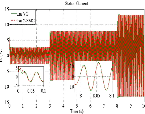
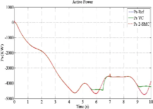
B. Simulation Results with Variable Speed Wind Turbine
In order to test the influence of the variation of wind speed for both strategies. The reactive and
active powers as well the stator current are illustrated in Figures (8 to 10), these results show that the suggested approach provides near-perfect performance in terms of system tracking performance
relative to classical vector control. However, noticeable improvements have been recorded thanks to the new approach.
Figure 8. Response of stator active power
Figure 10. Waveform of stator current
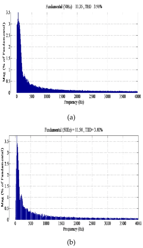
(a)
(b)
Figure 11. Stator current harmonic spectra, Ps = -5 kW, Qs = 0 kVar ,(a) VC, (b) 2-SMC.
Further to investigate the performance of the proposed scheme, the stator current harmonic spectra with Ps = -5 kW and Qs = 0 kVar for different control strategies are obtained as shown in Fig. 11. It
obtained by 2-SMC-SVM schemes.
7. 2.Simulation Results With Parametric Uncertainty
To study the influence of the electrical parameter variation on the behavior of the DFIG, we also simulated the system for a +150% of the nominal rotor resistance and inductance at time t = 5.5s. The
figure12 and 13 illustrates the evolution of the powers, we note from this result, the scheme (VC) has a slight variation due to the variations of Lr and Rr. The proposed method is robust against
parameter variations and allows a fast and suitable dynamic response.
Figure 12. Simulated results of stator active power.
Figure 13. Simulated results of stator reactive power.
Table 1 presents the quantitative analysis of the two approaches. The comparison among the presented techniques for power control implicates that the proposed scheme gives much less
chattering with a seamless transient response.
TABLE 1. Performances comparison of the two controllers.
Sensitivity to parameters
variation
Medium Low
Stator current spectrum (THD) Medium Low
Chattering Medium chattering Small chattering
Ps transient performance Medium settling time Fast with low settling time
Rising time of Ps 0.12 s 0.01 s
Qs transient performance Medium settling time Low settling time
Rising time of Qs 0.18 s 0.016 s
Implementation Complexity High Medium
8. CONCLUSION
In this paper, second order sliding mode control for DFIG has been presented. The suggested control
has been compared to the vector control. Simulation results demonstrate that the power ripples and total harmonics distortion (THD) are lower in second order sliding mode control compared with
classical control. The effectiveness of the proposed controller was verified using simulation tests with a 5 KW DFIG. Moreover, the proposed controller was examined for DFIG parameter variations
it has been demonstrated that the suggested algorithm gives better performance. The advantages of the suggested algorithm are highlighted by the following points:
1. Good robustness against the machine's parameter
2. Improvements of the stator current spectrum
.
APPENDIX
TABLE 2. Machine parameter and the WT values
Machine data WT data
Pn 5 KW R 3.1915m
Vs 220/380 V
N 2
In 16 A G 1
f 50 Hz J 7.68
Kg.m2
Ls 0.094 H f 0
N.m.s-1
P 3 References
1. T. Ackermann, Wind Power in Power Systems. John Wiley and Sons, 2005.
2. A. R. Solat; A. M. Ranjbar; B. Mozafari. "Coordinated Control Of Doubley Fed Induction Generator Virtual Inertia And Power System Oscillation Damping Using Fuzzy Logic". International Journal Of Engineering. Transactions A: Basics Vol. 32, No. 4, (April 2019), pp. 536-547.
3. H. Wanger, J. Mathur. "Introduction to wind energy systems. Green Energy and Technology", Berlin Heidelberg: Springer, 2013.
4. M. Tazil, V. Kumar, S. Kong. "Three-Phase doubly fed induction generator: An over view", IET Electric Power Application, (2009), pp. 75–89.
5. L. Yang, Z. Xu, J. Stergaard, ZY. Dong, KP. Wong. "Advanced control strategy of DFIG wind turbines for power system fault ride through". IEEE Trans Power Syst, Vol. 2, Issue 27, (2012), pp. 713–22.
6. R. Cárdenas, Peña R, Alepuz S, Asher G. "Overview of control systems for the operation of DFIGs in wind energy applications", IEEE Trans Ind Electron, Vol. 7, (2013), pp. 2776–98.
7. R. W. De Doncker and D. W. Novotny, “The universal field oriented controller”. IEEE Transactions on Industry Applications, vol. 30, No 1, (1994), pp. 92-100.
8. M. Reddak, A. Berdai, A. Gourma, J. Boukherouaa, "An Improved Control Strategy using RSC of the Wind Turbine Based on DFIG for Grid Harmonic Currents Mitigation", International Journal of Renewable Energy Research, Vol. 8, No. 1, (March 2018), pp. 266-273.
9. F. Amrane, A. Chaiba, Babes, B.E, Mekhilef, S. "Design and Implementation of High Performance Field Oriented Control for Grid Connected Doubly Fed Induction Generator Via Hysteresis Rotor Current Controller", Rev. Roum. Sci. Techn. – Électrotechn. Et Énerg, Vol. 61, No. 4, (2016), pp. 319–324.
10. F. Mazouz, S. Belkacem, Y. Harbouche, R. Abdessemed, S. Ouchen, "Active and Reactive Power Control of a DFIG For Variable Speed Wind Energy Conversion", IEEE 6th International conference on systems and control (ICSC’2017), Batna
Algeria, 2017.
11. S. Tamalouzt, I. Kassa. R. Toufik. A. Rachid, "Direct Torque Control of Wind Turbine Driven Doubly Fed Induction Generator", Rev. Roum. Sci. Techn. Électrotechn. Et Énerg, Vol. 61, No. 3, (2016), pp. 244–249.
12. M. Rasouli Khatir, H. Ghoreishy, S. A. Gholamian. "Virtual Flux Based Direct Power Control on Vienna Rectifier". International Journal of Engineering. Transactions B: Applications Vol. 31, No. 2, (February 2018), pp. 284-291.
13. C. Belfedal, S. Moreau, G. Champenois, T. Allaoui, M. Denai, "Comparison of PI and direct power control with SVM of doubly fed induction generator", journal of electrical & electronics engineering, Vol 8, No. 2. (2008), pp. 633-641. 14. K.S. Sarat, M. Balamurugan, P.L. Krishna, S.K. Prabhakar, "Comparison of SVM and DPC for reactive power control of
DFIG based wind energy systems", International Journal of Renewable Energy, Vol 11. No. 1, ( 2016), pp. 1614-1621. 15. M. Mariusz, J. Marek, M.P. Kazmierkowski, "Simple direct power control of three-phase PWM rectifier using
space-vector modulation (DPC-SVM)", IEEE Transactions on Industrial Electronics, Vol. 51. No. No. 2, (2004), pp. 447 – 454.
17. J. Zandzadeh, A.M. Vahedi. Improvement of direct power control of DFIG under unbalanced grid voltage condition. Electrical Power and Energy Systems 2014; 59: 58–65.
18. M. Farshadnia, T. Seyed Abbas. Current-based direct power control of a DFIG under unbalanced grid voltage. Electrical Power and Energy Systems 2014; 62: 571–582.
19. M. Darabian, A. Jalilvand. Predictive control strategy to improve stability of DFIG- based wind generation connected to a large-scale power system. Int Trans Electrical Energy Syst, Vol. 25, No. 2, (2017).
20. A. Bektache, B. Boukhezzar., Nonlinear predictive control of a DFIG-based wind turbine for power capture optimization, Electrical Power and Energy Systems, Vol. 101, (2018), pp. 92–102.
21. F. Mazouz, S. Belkacem, I. Colak, S Drid, “Direct Power Control of DFIG by Sliding Mode Control and Space Vector Modulation”, 7th International conference on system and control, IEEE (ICSC), Valencia – Spain, October 2018, 24-2 22. T. Douadi; Y. Harbouche; R. Abdessemed; I. Bakhti. "improvement Performances of Active and Reactive Power Control
Applied to DFIG for Variable Speed Wind Turbine Using Sliding Mode Control and FOC". International Journal Of Engineering. Transactions A: Basics Vol. 31, No. 10, (October 2018) 1689-1697.
23. B. Yang, T. Yu, H. Shu, J. Dong, L. Jiang. "Robust sliding-mode control of wind energy conversion systems for optimal power extraction via nonlinear perturbation observers". Appl Energy 2018.
24. T. Boutabba, a,b, S. Drid, L. Chrifi-Alaouic, M. E. Benbouzidd. "A New Implementation of Maximum Power Point Tracking Based on Fuzzy Logic Algorithm for Solar Photovoltaic System". International Journal of Engineering. Transactions A: Basics Vol. 31, No. 4, (April 2018), pp 580-587.
25. M. Nasiri, S. Mobayen, and Q. M. Zhu, "Super-Twisting Sliding Mode Control for Gearless PMSG-Based Wind Turbine", Hindawi Complexity Journal, Vol. 1, April 2019.
26. O. A. Morfin, C. E. Castañeda, A. Valderrabano-Gonzalez, M. Hernandez-Gonzalez, and F.A. Valenzuela, "A Real-Time SOSM Super-Twisting Technique for a Compound DC Motor Velocity Controller", Energies Journal, Vol, 10, (2017). PP. 1286-1304.
27. Levant A, Alelishvili L. "Integral high-order sliding modes". IEEE T Automat Contr. Vol. 52, (2007), pp. 1278-1282. 28. A. Levant. "Higher-order sliding modes, differentiation and output feedback control". Int J Control.Vol. 76, (2003), pp.
924-941.
29. Matraji I, Al-Durra A, Errouissi R, Design and experimental validation of enhanced adaptive second-order SMC for PMSG-based wind energy conversion system, Electrical Power and Energy Systems 2018; 103: 21–30
30. M. K. Salehi, R. Zeinali Davarani. "Effect of Different Turbine-generator Shaft Models on the Subsynchronous Resonance Phenomenon in the Double Cage Induction Generator Based Wind Farm". International Journal Of Engineering. Transactions B: Applications Vol. 29, No. 8, (2016), 1103-1111.