ABSTRACT
BARRETT, ROLIN FARRAR, JR. Mechanical Engineering Capstone Senior Design Course Textbook. (Under the direction of Eric Klang.)
This textbook is intended to bridge the gap between mechanical engineering equations and mechanical engineering design. To that end, real-world examples are used throughout the book. Also, the material is presented in an order that follows the
chronological sequence of coursework that must be performed by a student in the typical capstone senior design course in mechanical engineering. In the process of writing this book, the author surveyed the fifty largest engineering schools (as ranked by the American Society of Engineering Education, or ASEE) to determine what engineering instructors are looking for in a textbook. The survey results revealed a clear need for a textbook written expressly for the capstone senior design course as taught throughout the nation. This book is designed to meet that need.
This text was written using an organizational method that the author calls the General Topics Format. The format gives the student reader rapid access to the information
contained in the text. All manufacturing methods, and some other material presented in this text, have been presented using the General Topics Format. The text uses examples to explain the importance of understanding the environment in which the product will be used and to discuss product abuse.
follow design steps, helpful for both the student and new engineer. Prototyping is presented as consisting of three phases: organization, building, and refining.
MECHANICAL ENGINEERING
CAPSTONE SENIOR DESIGN COURSE TEXTBOOK
by
ROLIN FARRAR BARRETT, JR.
A dissertation submitted to the Graduate Faculty of North Carolina State University
in partial fulfillment of the requirements for the degree of
Doctor of Philosophy
MECHANICAL AND AEROSPACE ENGINEERING
Raleigh 2005
APPROVED BY:
___________________________ Chairman of Advisory Committee
BIOGRAPHY
Rolin Farrar Barrett, Jr., was born in Raleigh, North Carolina. He earned a Bachelor of Science in Electrical Engineering from North Carolina State University in 1986 and a Bachelor of Science in Mechanical Engineering from North Carolina State University in 1991. Mr. Barrett earned a Master of Science in Mechanical Engineering from Louisiana Tech University in 1996 and has worked to fulfill the requirements for a Ph.D. in Mechanical Engineering from North Carolina State University since 2000.
Mr. Barrett is a professional engineer and has been awarded design patents. Through his work as a consulting engineer, Mr. Barrett has analyzed more than 650 vehicle accidents, more than 175 fires and explosions, industrial accidents, ship and boat accidents, and
TABLE OF CONTENTS
LIST OF FIGURES ... vi
Preface ... ix
Chapter 1 - Working as a Team... 1
1.0 - This Book and You...1
1.1 - The Best Advice ...1
1.2 - Your Project...1
1.3 - Choosing the Team...2
1.4 - What to Expect at Your First Team Meeting ...2
1.5 - Small-Group Dynamics ...4
1.6 - Scheduling and Budgeting...5
Chapter 2 - Information-Gathering and Communicating Your Ideas... 7
2.0 - Introduction ...7
2.1 - Literature Reviews...7
2.2 - Learning the Environment ...8
2.3 - Analyzing Existing Designs ...13
2.4 - Plans and Drawings ...15
2.5 - Presentations...16
2.6 - Website ...18
Chapter 3 - Safety... 20
3.0 - Ethics ...20
3.1 - Regulations and Standards ...23
3.3 - Workplace Issues...29
3.4 - Power-Tool Safety...36
3.5 - Vehicle Safety Issues - Land ...44
3.6 - Vehicle Safety Issues - Air ...60
3.7 - Occupant Protection ...61
3.8 - Vehicle Safety Issues - Other Vehicles ...71
3.9 - Fire Safety and Burn Injuries ...74
3.10 - Agricultural Equipment ...81
3.11 - Recreational Products ...82
3.12 - Designing for the Elderly, Handicapped and Infirm ...85
3.13 - Discussion Topics...87
Chapter 4 - Design Principles and Creativity... 90
4.0 - Introduction ...90
4.1 - Key Principles ...90
4.2 - Inspiration and Creativity ...105
Chapter 5 - Application of Theory... 110
5.0 - Introduction ...110
5.1 - Hand Analysis ...110
5.2 - How to Gain the Most from the Steps ...117
5.3 - Key Steps...117
Chapter 6 - Preparing to Prototype... 128
6.0 - Introduction ...128
6.2 - Vendors...129
6.3 - Using Time Efficiently ...132
6.4 - Budget Realities...133
Chapter 7 - Building the Prototype... 134
7.0 - Introduction ...134
7.1 - Fastening Methods...134
7.2 – Bearings ...136
7.3 - Drives ...138
7.4 - Substituting Drives ...148
7.5 - Actuators...151
Chapter 8 - Testing, Evaluating, and Refining the Prototype... 159
8.0 - Introduction ...159
8.1 - Evaluating Your Prototype ...160
8.2 - Potential Trouble Areas ...165
Chapter 9 - Designing for Manufacture... 169
9.0 - Introduction ...169
9.1 - More Commonly Used Manufacturing Processes ...169
9.2 - Less Commonly Used Manufacturing Processes ...204
LIST OF FIGURES
Figure 1 - Typical muddy construction site ...10
Figure 2 - Keyless electric drill chuck...12
Figure 3 - Homemade grinder guarding...31
Figure 4 - Switch guard...32
Figures 5a and 5b - Integrated safety...33
Figure 6 - Slip and fall...34
Figure 7 - Lawnmower guarding...40
Figure 8 - Trimmer shield...41
Figure 9 – Pressure-relief safety...42
Figure 10 - Deform and absorb...62
Figure 11 - Fire safety...74
Figure 12 - Hair dryer filter...79
Figure 13 - Coffee maker...80
Figure 14 - Cork retainer...84
Figure 15 - Belt drive...140
Figure 16 - Gear drive...142
Figure 17 - Shaft drive...143
Figure 20 - Cable-and-pulley actuator ...152
Figure 21 - Cam actuator...153
Figure 22 - Gravity actuator...154
Figure 23 - Trip-lever actuator...155
Figure 24 - Spring actuator...156
Figure 25 - Blow molding...171
Figure 26 - Cold heading...173
Figure 27 - Drilling...175
Figure 28 - Extrusion...177
Figure 29 - Forging...179
Figure 30 - Grinding...181
Figure 31 - Heat treating...183
Figure 32 - Injection molding...186
Figure 33 - Lathe...188
Figure 34 - Material coatings...190
Figure 35 - Milling...192
Figure 36 - Roll forming...194
Figure 37 - Sawing...196
Preface
What This Book Offers
-
Chronological presentation of material
- Real-world examples
- General Topic Format
- Rapid access to information
- Key design principles
- Easy-to-follow design steps
- Step-by-step guide to ethics
- Unique safety content
Many books have been written about mechanical engineering design. Some of these books are widely used as references by mechanical engineers in their professional work. While these books offer equations and formulae for determining pertinent engineering data, they fail to convey the analytical thought that culminates in a safe and successful design. For example, current mechanical engineering design books may provide the student with the material necessary to calculate the design features of a stamped part and a machined part, but they seldom concisely explain why a stamped part might be preferred over a machined part.
Mechanical engineers do not design products that are independent of the world around them. Their designs must be competitive against other similar products while avoiding the pitfalls of cost and liability. This textbook is intended to fill the gap between mechanical engineering equations and the demands of mechanical engineering design.
student learns to calculate the flow of heat, the deflection of components under load, and the output and efficiency of engines, as well as how to conduct experiments. The third phase requires the student to apply the knowledge gained over the previous three phases. If any one course represents the application of mechanical engineering knowledge, it is the final mechanical engineering design course. The students are presented with an industry problem, and they must work in concert with a group of classmates to create a product that addresses the problem. They not only calculate and make decisions; they must also justify their decisions based on accepted engineering practices.
I was surprised by the similarity among the capstone senior design courses offered by the programs ranked in the ASEE's top fifty. Even more remarkable was how course
instructors told me they had little familiarity with the capstone senior design courses taught at other schools. Initially, I reasoned that the similarity was likely influenced by the guidelines of the Accreditation Board for Engineering and Technology (ABET) guidelines. However, examination of ABET guidelines revealed insufficient detail to account for the commonality. Future analysis may find a correlation between commonality of capstone senior design courses and industry feedback.
senior design course.
According to ASEE, the number of mechanical engineering degrees awarded
nationally has steadily increased, from 12,995 in 1999 to 13,769 in 2003. More than half of these degrees were awarded by the top fifty programs, with more than one sixth of the total number of degrees awarded by the top ten programs.
I spoke or communicated with instructors for the mechanical engineering capstone senior design courses at each of these top fifty schools. The most common answer to inquiries about textbook selection was that no textbook was in use for the capstone senior design course. The universal reason for no textbook being selected was that faculty teaching the course had judged no textbook to be worthy of adoption. Among those schools where textbooks were specified for the capstone senior design course, the books served as little more than reference material and were usually textbooks from a prerequisite course. In telephone conversations, every instructor teaching the capstone senior design course stated that it was necessary to provide additional faculty-written material to the students. This suggested that a need existed for a textbook written for the capstone senior design course taught throughout the nation. Instructors also often stated that the diverse range of topics taught in the course could not be found in any single textbook. Some schools selected multiple texts. One school selects five relevant texts for its mechanical engineering capstone senior design course every semester. Existing textbooks do not seem to satisfy instructors’ needs. All instructors expressed interest in a better textbook. The results of the survey revealed a clear need for a textbook written expressly for the capstone senior design course.
previously integrated into the programs of top fifty schools, but safety has not generally been included. Some faculty suggested that "case studies" should be included in a safety chapter.
Safety has been explored as a separate chapter in this text. A thorough discussion of safety requires an explanation of rules, recommendations, standards, and the entities that create them. A chapter on safety should include key safety concepts and the legal implications of product failure. Such a chapter should also explain to the mechanical
engineer the importance of understanding the environment in which the product will be used, and the chapter should give the mechanical engineer an understanding of product abuse.
Most of the instructors expressed the opinion that ethics was an important topic in the course. Despite the overwhelming support for ethics, only one ASEE top fifty school has a dedicated ethics text.
Safety and ethics are almost always overlooked or undervalued in mechanical engineering design books. Ethical issues are presented as little more than an injunction to "Do the right thing", while offering the student an unrealistic view of the professional world. Such advice might work if the engineer's co-workers were always completely honest and impartial and the engineer wealthy enough to weather all possible legal problems. Sadly, such simplistic advice is of little use to a new engineer with dependents, debt and a mortgage, who might jeopardize a promising career by calling attention to a safety issue. At a time when the new engineer must balance conscience, legal liability, and professional career, a step-by-step analysis of ethical engineering procedures is needed.
manufacturing process presented in this book using the General Topics Format is illustrated below.
Process: Abrasive-flow machining, abrasive jet machining17 How it is used: Polishing turbines and complex shapes Advantages:
- Little heat is generated.
- Causes no heat damage to the workpiece. - Suitable for finishing inaccessible surfaces. Disadvantages:
- Equipment is expensive. - Slow material removal.
- Poor tolerance control (10%-50% common, 25% normal).
Abrasive-flow machining is performed by transporting an abrasive-filled viscous semisolid medium across the surfaces of the workpiece. As the viscous semisolid medium is pumped across the workpiece, the abrasive particles rub on jagged edges and other sharp features, slowly removing the tiny protrusions. The finished part is analogous to a shiny, well-worn boat propeller that has been polished by sand particles suspended in the water. ...
Many mechanical engineering design books have been written to show how to calculate relevant design features, but few authors have explained why engineers make the choices that they do. The purpose of these chapters is to convey some of the lessons of experience learned by mechanical engineers. Each engineering problem and each solution will differ, so there is no handy formula to cover every possibility. However, the engineer with a good understanding of engineering ethics and safety and the will and ability to incorporate these concepts in optimal designs will excel.
Chapter 1 - Working as a Team
1.0 - This Book and You
This book was written specifically to be a textbook for the capstone senior mechanical engineering design course that is taught in most major universities. Though the reader may be a senior in the undergraduate mechanical engineering program, he or she is referred to as the engineer throughout the book. It is the author’s hope that this book will serve you well, both in the capstone senior mechanical engineering design course and in your engineering career.
1.1 - The Best Advice
If there is any secret to achieving a high grade in this course, it is to quickly build an effective team. The capstone mechanical engineering senior design course is normally taught over one semester. The actual time available for working on the group project is about fourteen weeks. In fourteen weeks, each team will have to conceive a design, communicate that design, construct a prototype, test the prototype, and correct any deficiencies.
1.2 - Your Project
In this course, you will work as a team member to solve a real-life problem. This problem has been posed by an industry sponsor who has also provided funding to purchase supplies and pay for equipment usage. As part of a team, you will analyze the problem and create a viable solution. Your solution must be based on sound engineering principles.
Because your ideas are of little use if you cannot communicate them in an easily understood manner, this course requires that you present your solution through a set of plans, as well as oral and written reports.1
1.3 - Choosing the Team
Your instructor may allow the students to form their own teams. If this is allowed, certain skills should be sought, regardless of the project. It is desirable to have members with proficiency in: computer aided drafting (CAD), technical writing, welding, machining, basic hand tool usage, and other relevant areas.
Some instructors opt to assign students to their respective teams. This is far more representative of the workplace that the new engineer will likely face after graduation. Additionally, the use of instructor-selected teams removes the burden of team selection from the students.2
1.4 - What to Expect at Your First Team Meeting
Your team probably will consist of four to eight students. From the beginning of the first team meeting, a phenomenon called group dynamics—how people interact with one another—will be a factor influencing the work of your group. Some individuals will feel comfortable speaking, while others prefer to remain quiet.3 Your group’s goal should be to leave this meeting as an organized team.
Try to hold your first team meeting in an unoccupied room with a chalk or ink board. List your team members’ names on the board. Beneath each name, write the skill (CAD, technical writing, welding, etc.) that the team member considers his or her strong point.
best oversee the successful completion of the assigned project. Ideally, the leader should be mature, experienced in teamwork, and somewhat diplomatic in personality.5 The team leader will need to keep accurate data on the team’s budget and scheduling.
During the semester, the team leader may be absent due to a test or illness or may simply be overburdened by the team’s needs. For this reason, you should also choose an assistant team leader. The assistant team leader can share some of the responsibilities of contacting team members and vendors.
At this first team meeting, you should discuss the problem statement. This stage is sometimes called brainstorming. It is a method of gathering and organizing ideas. Do not berate or ridicule the ideas of any team member, since this can lead to future confrontations, a reluctance to reveal new ideas, a divided team, and almost certainly a lower grade in the course.
If you strongly disagree with an idea, use engineering facts to confront it. Remain objective and refer to the idea, not to an individual who favors the idea. For example, if your idea is to use a four-bar linkage, refer to it as “the four-bar linkage” and not as “my idea.” If you call an idea “stupid” or “bad” (or worse), those team members favoring the idea may take your remark as an insult. Speak in terms of advantages and disadvantages of a given idea.4
By the third or fourth week of the course, the team will have to submit drawings and possibly a written or oral report of their design for the project. This necessitates CAD plans, so you should choose two members who will do the actual CAD drawing. Technical writing skills will also be beneficial.
1.5 - Small-Group Dynamics
During the semester, your team may experience some of the classic interactions among members that have often been observed in small groups. (For the purposes of this section, assume that there are six to eight people in your team.)
Two individuals may vie against each other for the leader’s position or control of the group. When the group selects a leader, it becomes incumbent upon the rest to work as loyal members of the team. Should you observe a problem in this area, remind members that course grades will depend on their success as a team. If the conflict continues to grow, you may wish to consult privately with the instructor, but this is best left as a last resort.
At the other extreme is a team member who is consistently absent from team meetings or who simply refuses to contribute.6 In an eight-member team, seven can complete the work with little added difficulty. Even in a six-member team, five can complete the work in a timely manner. Remind disgruntled team members that the “fairness” issue created by a non-contributing team member can be resolved by consultation with the instructor or by peer grading if that is an option.
1.6 - Scheduling and Budgeting
Every project will have a schedule and a budget. Your team’s ability to adhere to these will influence your grade. The schedule may specify only a presentation date, but your team will need to add intermediate steps and their corresponding dates in order to keep up with the rest of class.7
The budget can be addressed in the design phase. As part of the design process, you should estimate the costs of the raw materials. For many products, the cost of labor is a more significant contributor to the final price than the material costs. Remember, besides adding to the final cost of the prototype, a labor-intensive design adds to your team’s time in the shop during the semester.
One way to facilitate planning is to use calendar software. Print the relevant months with entries for the appropriate date and time of important deadlines as well as for future group meetings or work sessions. Regularly update the calendar, and print copies for all of the team members. Mark the version of the updated calendar to avoid confusion with previous versions of the calendar. Your team may wish to mark the calendars with numbers or letters. For example, the fifth updated calendar might be marked “5” or “E” (the fifth letter of the alphabet).
Chapter 2 - Information-Gathering and Communicating Your Ideas
2.0 - Introduction
In engineering, as in the rest of life, each generation builds upon the achievements of the previous generation. Few innovations would result if every generation of engineers had to reinvent the wheel. This chapter shows the designing mechanical engineer how to find technical knowledge about his design project.
Before a mechanical engineering team can create a superior design, they have to learn about existing designs. In studying existing designs, the mechanical engineering team can determine specific shortcomings that their design should avoid. This chapter gives the mechanical engineering design team a guide for the evaluation of existing designs.
The best ideas in the world are of little value if they are not communicated to others. This chapter also discusses ways to present the mechanical engineering design team’s ideas in a clear and concise manner.
2.1 - Literature Reviews
The mechanical engineering design team should begin the design process by researching the problem. In the capstone mechanical engineering course, information about the problem will most like be revealed in the first or second lecture.
A helpful first step in the literature review is to use Internet search engines to find relevant websites. Websites of particular interest include manufacturers’ websites, product review websites, and articles that seek to inform the reader about the role of existing designs.
After researching Internet resources, team members should review relevant articles in journals and technical publications. These can be found in the university library. In the unlikely event that a needed journal article cannot be located, design team members should search online article repositories. These online repositories usually charge the purchaser a small fee for the article.
2.2 - Learning the Environment
No amount of reading can convey the lessons offered by visiting the work environment. Some of the more important information to be obtained by a visit by the mechanical engineering design team will include the types and quantities of debris, user skill level, and real-world product maintenance.
Example #1
A mechanical engineering team has been asked to design a conveyor-belt-mounted grasper for use at an inspection station in a poultry processing plant. None of the team members has any experience with the poultry industry. In order to learn about the environment in which their design will be employed, the entire team has arranged to visit the poultry facility.
While the team members are waiting, the security guard recommends that they bring their coats into the plant, as the entire facility is refrigerated. The team’s escort arrives and asks if the team members are wearing slip-resistant shoes, because the floors in the work areas are always wet. Already the team has learned that the work environment is cold and wet.
The team’s escort leads the team into the work area and the surroundings are unlike anything that they have ever experienced. The work area is a sea of employees and stainless steel machinery, with literally thousands of chickens in various stages of processing rapidly passing overhead in different directions. The sound level of the machinery makes conversations strained. The most overwhelming sensation is the smell of sanitizing solutions. The team members begin to realize that space is at a premium and the work pace is more hurried than they expected.
A mixture of water and sanitizer seems to cover every surface of the work area and drip down from above. The team members all recognize that their design must be impervious to these liquids. The team also knows that their design must be operable by an employee with cold, wet hands.
The team members are now convinced that their design must be easily cleaned by the procedures they have witnessed. The team will be certain that their design does not have any recessed features that could hold contaminants. The team members have learned a lot from their brief visit.
Example 2
Fig. 1. Typical muddy construction site.
Upon meeting the corporate sponsor’s representative, the team members are issued safety glasses and hard hats. The team’s members who thought that the gravel parking lot looked dirty will soon realize that it was one of the cleaner areas at the site.
The team has arrived at the construction site on an unusually hot and humid day. The city has received heavy rain for several days, and the construction site looks like a sea of mud as soft as pudding, punctuated by deep water holes. Projecting from the mud are large steel I-beams forming a partially assembled structure.
As the team and their corporate sponsor’s representative weave their way around the water holes and other hazards, the team’s members begin to appreciate the potential for debris-induced failure in any power tool used at the site. As the team members strive to keep their balance in the mud, the corporate sponsor’s representative remarks that after the mud dries, even a gentle breeze will blow the soil across the site until everything is covered by a thin layer of dust. The corporate sponsor’s representative remarks that mud typically clogs the cooling air vents on power tools and that dry soil disables bearings. Already the team has learned that their drill design must be able to operate in a debris-filled environment, regardless of whether it is wet or dry.
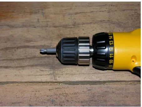
One of the team’s members notes that any small tool dropped into the mud or a water hole is almost certainly lost. This remark leads the team members to conclude that the drill should have a keyless chuck easily turned with a wet or muddy hand.
Fig. 2. Keyless electric drill chuck.
The construction workers themselves pique the curiosity of the team members. The team has noticed that the construction workers speak different languages. Among the languages heard are Spanish, Russian, and Polish. The corporate sponsor’s representative explains that most of the workers are foreign nationals who have obtained work permits. These workers usually cannot read or write English, and some cannot read or write in any language, so they often learn to use power tools by observing their coworkers. The team members understand that the controls on their drill design must be intuitive, possibly with tiny symbols embossed into the drill housing adjacent to each control, illustrating the control’s function.
Despite the value of good tool maintenance, none of the tools is observed being lubricated. Even those construction workers who attempt to clean their power tools simply wipe the tool down the front of their dirt-encrusted T-shirts. Power tool cooling air vents stay clogged. The team resigns itself to the fact that few tools get the care and maintenance that their manufacturers specify.
The work environment visited by the team is far removed from the pictures in tool catalogs. As a result of their trip, the team has a new outlook on power tool design.
2.3 - Analyzing Existing Designs
The fact that there is a need for a new product is evidence that existing products do not satisfy the needs of the marketplace. In order to understand the advantages and disadvantages of existing products, the mechanical engineering design team should evaluate the designs of those products.
attention to how existing designs overcome known problem areas, such as debris-induced failure, fatigue failure, and maintaining the alignment of precision parts.
Example
The mechanical engineering team in the earlier example has gathered to analyze samples of the three best-selling currently available battery-powered drills. The team members have decided to analyze the exteriors of the drills first. After they have finished with the exteriors, the team members will open the drills and analyze the design features found inside.
The team members immediately notice that the batteries of all three drills resemble boxes or ovals, each with a vertical column that inserts into their drill’s handle. As a result, the centroid of each battery hangs directly below the user’s hand. Because the body of each drill is positioned forward of the user’s hand when properly held, each drill has a slightly uncomfortable forward balance. The team members discuss positioning their battery’s centroid to the rear to give their drill a more comfortable balance.
The team members observe that all three of the drills they are studying feature a keyless chuck. This allows the user to insert and secure drill bits and drive accessories without the use of a special tool. The team members acknowledge that their drill design needs to have this same feature.
shocked by accidental contact with an active conductor. The team members agree that their drill should have an all-plastic body.
All three drills use an impellor to circulate ambient air for cooling. The impellor is located in the forward half of the body in all three drills. All three drills feature long, narrow, vertical slots positioned on both the left and right sides of the drill body. The slots expose the impellor blades to aid air flow exit. At the rear of all three drills are louvered air intake ports. The team decides to design their drill’s cooling air vents so the user may easily clear debris from the vents with a common flat-blade screwdriver.
Examining the interior of the three drills, the team notices that a device called a thermal protector has been incorporated into each drill. Researching thermal protectors, the team members learn that thermal protectors interrupt the electrical power circuit when the temperature exceeds a predetermined value. The purpose of using a thermal protector in this application is to prevent the drill from catching fire or melting the plastic components. The team reasons that their drill should have a thermal protector.
The team continues by examining the bearings, gears, and motors. They recognize that placing the gears in an integral package would allow for fast assembly and repair times. The team members discuss using a gear housing that would either be cast or formed from stamped steel.
The team debates the merits of using a brushless motor. A brushless motor would be more expensive but would not have exposed sparks that might ignite a flammable vapor. 2.4 - Plans and Drawings
known as drafting. Now technical drawings are created by means of computer-aided design (CAD).
The purpose of the drawings is twofold: reproduction and improving the design. Technical drawings enable the product to be produced by people who have no prior knowledge of the design. For example, if an electric can opener is designed and built in Belgium, high-quality technical drawings to would allow the product to be reproduced by a company in Argentina with skilled engineers and manufacturing personnel.
Technical drawings can assist the mechanical engineering team in improving their design. The team members can study the drawings for obvious flaws, such as overlapping holes. Technical drawings also allow the team members to visually analyze the position of each part as it relates to the other parts.
Subassemblies should have their own set of drawings. The main drawings should clearly refer to the appropriate drawings for the subassemblies. The drawings should also reflect how subassemblies connect to the main portion of the product.
2.5 - Presentations
Few moments in product development are as brief, or as important, as the presentation. During the presentation, the designing mechanical engineers must convey a wealth of technical detail to non-technical people so as to win their enthusiastic support, in a few minutes, without losing their attention.
Throughout the presentation, the team’s speakers should conduct themselves in a professional manner. The speakers should strive to give the appearance of competent, dependable, knowledgeable, mature engineers.
It is inappropriate for any team member to wear a shirt with offensive writing during a presentation. The purpose of a presentation is to show the audience why your team’s design has merit. Offending the audience will reduce your team’s chances of winning over the audience with your design.
The team member’s clothes should be clean, orderly, and appropriately chosen. If the audience will be wearing dress business attire, then so should the engineering team members. Ideally, the team’s members should be dressed slightly more formally than the audience. The team members’ clothes do not have to be expensive, just suitable for the presentation. Posture also sends a message to the audience. Professional appearance means always conveying that you are a capable and dependable engineer. The team member should mentally place him- or herself in the role of the audience to better understand this issue.
Suppose that two mechanical engineers give identical presentations. The only difference is that the first engineer slouches, looks down at the podium, and at times is difficult to hear. He presents the material while wearing ragged jeans and a T-shirt with festooned with holes, various food stains, and the name of the engineer’s favorite bar. The second engineer stands erect, engaging the audience with eye contact. She speaks clearly and confidently about a design with which she is obviously familiar. The second engineer wears business clothes, has an orderly appearance, and displays an enthusiasm for the design.
investors? Appearance, gestures, posture, and speaking voice all contribute to the overall quality of the presentation.
The mechanical engineering design team will benefit by structuring the presentation in five parts. The first part should be an introduction, beginning with a one- or two-sentence statement about the team, with the speaker naming the team members. This is a personal touch illustrating to the audience that the team members are real people who have put forth their best creativity and engineering talents. The introduction should conclude with the problem statement.
The second part of the presentation should briefly explain the approach taken by the mechanical engineering design team to solve the problem in the problem statement. The team’s speakers should use this opportunity to state the logic that led to the design.
The third part of the presentation should explain how the team transformed the design into a real prototype. This section doesn’t have to discuss every nut and bolt. However, it should be used as a way of proving to the audience that the team has transformed theory into reality.
The fourth part of the presentation should present the prototype’s test results. This section should demonstrate to the audience that the designing team has succeeded—that they achieved what they set out to accomplish.
The fifth part of the presentation should be the conclusion. It should summarize the presentation.
2.6 - Website
post their questions or comments to the team. The team website also allows rapid communication from the course instructor. The instructor need only post information to the team websites to inform all students of new course material.
A website can serve as a type of continuous presentation. Unlike human engineers, the website can present the team’s design at any hour or any day. By maintaining a website about their work, a designing mechanical engineering team can reach a far larger audience than would be possible without the website.
Composing the website is not enough to realize its maximum utility. The mechanical engineering design team needs to take some simple steps that will allow the website to be found. The first step is to list the website with several popular search engines. If someone performs a web search for “mechanical engineering design” and “prototype”, the team’s website will be among the returned list of search results.
Chapter 3 - Safety
3.0 - Ethics
Where used: Throughout engineering Ethics issues:
1) Ethics are the foundation of safety and the consumer’s trust in the engineer. 2) Specific laws and standards exist to maintain ethics and safety.1
3) Well-defined ethics steps exist for engineers to follow.
There is perhaps no concept more fundamental to engineering than safety. When a consumer chooses a product, the choice implies the consumer’s confidence that safety was incorporated into the design. In order for a product to be successful, the designing engineer should balance function, safety and cost.
Consumers often address safety concerns by confirming that the product meets standards established by commercial testing facilities, government agencies, or professional organizations. The purchaser of an appliance may examine the packaging for the mark of a respected testing laboratory. The purchaser of an automobile may read government automobile crash test ratings. The purchaser of air-conditioning equipment may select a product because it meets ASHRAE standards.
accusing them of sensationalizing and exaggerating. In time, workplace safety emerged as an important issue to many Americans. Although few statistics on workplace injuries were recorded during the early twentieth century, conversations with people alive during that period reveal that it was common to see people missing a limb or eye due to workplace accidents. In the textile industry, many machines manufactured in the 1920’s are still in use. The absence of proper guards on these machines continues to result in workplace injuries.
3.1 - Regulations and Standards Where used: Throughout engineering Regulation and standards issues:
1) Specific laws and standards exist to maintain ethics and safety.
2) Federal, state and local government agencies enforce safety regulations.
3) Professional societies and private organizations often have their own regulations and standards.
In order to protect the public, regulations and standards exist that relate to most engineering applications. Regulations have been established at federal, state and local levels to promote safety. A list of the Federal regulatory agencies that relate to engineering design would include but not be limited to NHTSA, NTSB, OSHA, FDA, and EPA.
Formed in 1970 under the Department of Transportation by the National Highway Safety Act, the NHTSA (National Highway Traffic Safety Administration) works to reduce motor vehicle economic losses, deaths and injuries.3 NHTSA aims to improve safety by regulating automobile design, studying traffic flow and driver behavior, and investigating safety defects in motor vehicle design. NHTSA also sets and enforces fuel economy standards as well as vehicle anti-fraud and anti-theft regulations.
OSHA (Occupational Safety and Health Administration) takes its name from the Occupational Safety and Health Act of 1970.4 In compliance with this legislation, OSHA was formed in 1971 to address workplace safety and illness.
The FDA (Food and Drug Administration) has relevance to engineers designing for the food, medical and pharmaceutical industries. The FDA began as a single chemist in 1862 operating under the Department of Agriculture.5 An example of the FDA’s relevance can be found in their Good Manufacturing Practices/Quality System Regulation guidelines, which specifically affect the design of manufacturing and processing equipment.
The EPA (Environmental Protection Agency) was formed in 1970 and regulates the design of engines, manufacturing equipment, and water treatment mechanisms, among other items.6
In addition, many of the functions of federal regulatory agencies are supplemented or duplicated at the state and local levels.
a regulation, it has the power of law. Reputable designers always consult the consensus standards.
In a manner similar to consensus standards, third-party testing laboratories also let consumers know that a product meets one or more known standards of that laboratory. Perhaps the third-party testing laboratory best known to American consumers is UL, Underwriters Laboratories Inc.
It should be readily apparent that government regulations and consensus standards play a role in all aspects of engineering. The mechanical engineer designing a device will find the design process much easier if he or she takes the time to research the applicable regulations and standards.
3.2 - Concepts
Where used: Throughout engineering Safety issues:
1) Fundamental safety concepts help ensure the safety of a design. 2) Safety concepts have been proven trough trial and error.
3) Always try to incorporate safety into the basic design.
this engineer examined and tested an emblem press and an industrial paper cutter, neither of which had failed safe during an actual equipment failure. Serious personal injuries resulted.
A truck tractor’s air brake system is connected to its semitrailer’s air brake system by two air hoses. One of these hoses serves the semitrailer’s normal air brakes. The other air hose is the emergency air supply. If the emergency air hose connection is severed, the semitrailer’s emergency spring brakes will be activated. This allows the semitrailer’s brakes to fail safe.
In the Caribbean and in other clear waters, tourist submarines are a popular attraction. They are equipped with a row of windows on each side, allowing passengers to safely and conveniently enjoy the underwater beauty of the sea. These tourist submarines are all electric-powered. To ensure safety, they have a positive buoyancy. This means that the submarine must use power to remain submerged. If the submarine were to become disabled, it would gently float to the surface. With this safety feature, the tourist submarine that fails will fail safe.7
It is always desirable for the mechanical engineer to design in redundancy. The spare tire in an automobile is an example of redundancy; five tires are carried when only four are needed. Many aircraft warning lights consist of a plastic optical conduit with multiple bulbs providing light for that single warning feature. The pilot sees the illuminated conduit when the warning feature is activated. Should one bulb burn out, the other bulbs can communicate the warning when necessary.
this engineer examined a wood press in which the safety had been bypassed in an effort to improve productivity, with tragic consequences. The engineer should strive to design safety features that function without conscious thought by the product operator.
Account for some degree of product abuse in safety design. The agricultural industry is an example where product abuse may be encountered. Many agricultural workers have little or no formal training in the operation of tools and machinery. This is especially true in underdeveloped nations. The long hours and hard physical labor common to agricultural work can leave the workers tired and less alert to potential hazards.
Selecting design features that minimize maintenance, or at least make maintenance more convenient, reduces the occurrence of accidents. Applications involving wire rope and hydraulics are examples of mechanisms that can benefit from this design approach. Wire rope requires frequent inspections. If those inspections can be easily made, they are more likely to be made. Hydraulic mechanisms, such as those used in lifting machinery, normally require daily maintenance. When lubrication ports are difficult to reach, consumers may neglect lubrication, leading to failure.
Commonality of operation procedures enhances safety by easing consumers’ transitions to the product. This would include such steps as positioning any controls and hand grips of a power tool in the same locations as on other similar products.
All designs should incorporate a safety factor. The safety factor is the quotient of the expected load and the load at which a component fails. The safety factor chosen depends upon the application. A larger safety factor may tolerate more abuse and better resist fatigue than a low safety factor. Conversely, a large safety factor may result in a bulky or overweight component that is unable to compete with rival designs. When a product has an unreasonably large safety factor, it may be said to be overdesigned. Safety factors for many common products are between 1.25 and 1.75, according to the application. Consensus standards often include guidelines for choosing an appropriate safety factor.
Product liability is a significant issue for the mechanical engineer. If a product fails and personal injury results, it is nearly certain that questions of civil liability will arise. During this litigation, the designing mechanical engineer can expect his competence and ethics to be examined.
For reasons of product liability, some manufacturers favor design features that hinder unsafe modification of their products. These features include tamper-resistant fastening and devices to restrict the space available for installing unsuitable components. Some manufacturers use mechanisms that indicate when someone has tampered with their product. These may include seals that display lettering when removed or threadlocking materials with proprietary compositions. Should product-liability litigation result, evidence of tampering can absolve the manufacturer of blame. A small number of well-publicized product tampering incidents during the 1970s led to the use of tamper-resistant seals on food and drug products. A popular American trailer rental company has used proprietary safety chains. To the average trailer renter, these chains would appear the same as other similar safety chains. This engineer has examined safety chains that were alleged to have failed on this company’s trailers. The claims were that the failed chains caused personal injury accidents. In each of these claims, the evidence chains were shown not to be the original safety chains.
Incorporate guarding and shielding in the design, even if no regulation or standard calls for it. Examples of places where guarding is useful include chains and sprockets, meshing gears and other mechanical pinch points. Lawn care equipment is an example of where shielding is beneficial. Rocks and other debris may be propelled at dangerous speeds from beneath mowers, trimmers and edgers.
3.3 - Workplace Issues
Where used: Occupational locations Safety issues:
3) Design for safe maintenance.
Workplace hazards that the mechanical engineer should consider include but are not limited to machine operation, vehicle operation, the potential for worker slips or falls, burns, and electrical shock. Electrical shock may seem outside of the responsibility of the mechanical engineer, but it is not. The author once examined a lighted storefront sign in which the mechanical engineer had designed an incandescent light fixture sufficiently close to electrical wiring for the heat given off by the light to degrade the wiring insulation over time. Eventually, a customer touched the sign and was electrocuted.
The traditional method of designing machinery has been to focus on the objective of the design and the anticipated forces to which the design will be subjected. The mechanical engineer can benefit greatly by taking another step first. The mechanical engineer should endeavor to learn about the environment in which the machine will be used.
Machine guarding
Fig. 3. Homemade grinder guarding. This guarding provides excellent protection against injury.
Maintenance access
Fig. 4. Switch guard. Guarding can also prevent unintentional activation.
Worse, workers sometimes attempt maintenance while the machine is in operation. They frequently do this because they think it will save them time or to avoid lost productivity. Machine safeties
Figs. 5a, 5b. Integrated safety. This wooden mockup of a manufacturing machine illustrates how safeties can be integrated to ensure that both of a worker’s hands are clear of the dangerous parts prior to operation.
should be designed into the machine to automatically disable the machine during maintenance.
Slip and fall
Fig. 6. Slip and fall. Slip-and-fall injuries highlight the importance of good design of shoe soles and walking surfaces.
Vehicles around workers
Many work environments include vehicles operating among pedestrian workers. Safety in this type of setting has traditionally included horns, reverse-actuated alarms, rotating amber lights, strobe lights, and safety cages for vehicle operators. Safety cages protect vehicle operators from falling objects. Horns function just as they do on automobiles, enabling the driver to warn pedestrians or other drivers. Rotating lights and strobe lights are an especially valuable asset in noisy work environments. Reverse-actuated alarms require no thought by the vehicle operator to function. A more recent design approach has been the inclusion of proximity and presence detectors. The two most common methods of presence and proximity detection are sonar and radar. Reduced electronics manufacturing costs have begun to make sonar and radar economically viable options. The author once examined a sanitation truck that had killed a sanitation worker during a three-point turn. If a detection system had been available on the sanitation truck, this accident likely could have been prevented.
Hazardous chemicals
Because many maintenance personnel may neglect or be unaware of the safety steps necessary for working around hazardous chemicals, the mechanical engineer may want to design the size and placement of human access ports to promote proper ventilation (convenient safety).
3.4 - Power-Tool Safety
Where used: Power tools operated by or near humans Safety issues:
1) Address mechanical safety, electrical safety and user issues. 2) Account for operator misjudgment when possible.
3) Learn about the environment in which the tool will be used.
User issues are more complicated than simple safeties. The engineer needs to learn about the debris, chemicals and weather to which the tool will be subjected, as well as how the targeted consumers use existing power tools. Some power tool users apply excessive force to tools, exceeding the recommendations of the manufacturer. Excessive force can not only accelerate wear; it can burden a tool’s electric motor, raising the risk of overheating. Example
Let us assume that a mechanical engineer has been asked to design a portable band saw to be marketed to industrial plumbing contractors. Band saws are held by two hands and may be used to cut in different orientations, including inverted. Band saws normally use an electric motor to turn a continuous steel band blade fitted with cutting teeth along one edge. The band is wrapped around two wheels, one of which is powered by the electric motor. Operation of band saws is normally controlled by the application of index-finger pressure on a trigger-type electrical switch. Many saws are configured to allow the trigger switch to be locked in the “on” position to lessen hand fatigue. Cutting takes place along the segment of the band blade between the two wheels, moving toward the user. The other segment of the band blade is normally guarded.
engineer may hear that existing designs become easily clogged with debris, are too heavy, or suffer frequent parts breakage. It may prove valuable for the engineer to ask consumers about the ergonomics of existing designs, common sizes of pipes to be cut, and even the number of hours a day that they spend working. This last question may provide insight to the tool’s life and the safety alertness of the consumer. A tool that stays in near-constant use may receive little care or maintenance. A consumer is likely to be less safety conscious after working for eleven hours than after six hours, increasing the chance of tool misuse. While watching consumers at work with existing band saws, the engineer should try to estimate the force with which the worker holds the blade against the pipe. This can be later duplicated in controlled tests with force gauges. Do consumers consistently wear eye protection? Do they keep their electrical cords and power sources away from pools of water? Armed with this information, the engineer is better able to design the product.
Engine-powered tools
Where used: All engine-powered tools Safety issues:
1) Prevent exposure of people to missiles or burns from tool. 2) Prevent the ingress of body parts.
3) Use integral safeties such as pressure-release switches.
Many tools and machines need to cooperate in locations that are remote from electrical power or without the limitations of long electrical power cords. These tools are normally powered by small gasoline or diesel engines. Common examples include lawnmowers, chainsaws, edgers, trimmers, augers, and blowers.
Fig. 8. Trimmer shield. These must allow for tools to be used in confined spaces.
Fig. 9. Pressure-relief safety.
An auger is a tool that uses an engine to turn a large spiral screw for drilling holes in earth. The tool is usually oriented to place the screw tip against the soil. In this orientation, the engine sits atop the screw, with the X-shaped handles immediately beneath the engine. Large augers may be configured for use by two operators. The primary safety concern with augers is that the users’ feet not contact the large spiral screw.
avoided by incorporating guarding and heat shielding in the blower’s design. Hearing loss is a more persistent problem. Even when the employer emphasizes the need to wear hearing protection, blower operators may not understand the importance of this safety feature. Blower operators may mistakenly reason that if the blower engine noise is not causing pain, no hearing damage is done. Another concern is the hearing loss a blower engine may cause to other people nearby. State legislation is increasingly restricting engine-driven blower operation due to objectionable noise. All of these hearing-loss concerns could be best addressed by designing noise reduction features into the blower before manufacture.
Modern chainsaws are examples of how unobtrusive safety features can be incorporated into the design of an otherwise dangerous machine. Chainsaws consist of an engine, a thin bar extending from the engine with a rounded free end and grooved edge, and a continuous engine-driven chain blade that traverses the grooved edge of the bar. The chain blade consists of a roller chain fitted with small protruding individual blades.
The chainsaw user holds the tool by purpose-built handles at the engine end. The rearmost handle is fitted with the controls and a grip safety. The grip safety must be depressed for the tool to operate. The forward, or supporting, handle is positioned above the juncture of the chain and bar with the engine. The user’s supporting hand is protected from slippage-induced contact with the chain blade by guarding placed immediately forward of the supporting hand position.
have sought to prevent kickback by adding guards to the tip region of the bar, preventing the chain blade from contacting objects. Unfortunately, guarding can become detached with use or be intentionally removed should the tip guard be viewed as reducing tool efficiency. The best solution to this safety problem has been the design and implementation of anti-kickback chain blades.
3.5 - Vehicle Safety Issues - Land
Vehicles are vital to modern economies, transporting food, fuel, products, workers, and tourists. Vehicles sharing the same roads vary in size from a 500-pound motorcycle and rider to an 80,000-pound truck. Arguably the greatest influence of safety research can be observed in the design of vehicles, and with good reason. Even the largest and most advanced interstate highways mandate that the driver of an eight-foot-wide truck tractor and semitrailer steer the vehicle within a 12-foot-wide lane while covering a distance nearly as long as an American football field in three seconds.
to safety concerns. Many rocket fuels cause burns upon contact with skin, illustrating that the mechanical engineer needs to consider more than just the technical numbers.
Turbine engines
Where used: Aircraft, petroleum pipeline pumps, emergency power generation Safety issues:
1) Excellent reliability. 2) Slow throttle response. 3) Dangerous exhaust heat.
Although popular in aircraft, turbine engines have yet to gain favor in vehicles. The advantages of turbine engines include a high power-to-weight ratio, multi-fuel ability, and greater reliability than reciprocating engines. The disadvantages of turbine engines include the heat of their exhaust, their long response time to a new throttle input, and their cost. Turbines were experimentally tried in automobiles as early as the late 1950’s, but they have yet to be used in a production automobile. Even if mass production of turbines for automobiles resulted in lower costs, the heat of their exhaust and their long response times to new throttle inputs would remain unresolved. Few drivers would be willing to wait several seconds for their automobile to begin moving forward when the stoplight turns green. Imagine the difficulties associated with parking and merging into traffic with an engine response time significantly longer than that for reciprocating engines.
case of turboprop airplanes and turbine-powered helicopters. While operating on the ground, only trained personnel approach aircraft and only from certain directions known to be safe. The turbine-powered automobile would not have this luxury. Pedestrians of every stripe walk near a multitude of automobiles every day. If automobiles featured jet exhaust as used in the fictional (but fascinating) Batmobile, severe burns could result. Under the best of circumstances, damage would occur to following vehicles, the tires of the vehicle in question, or to the pavement beneath. As a result, it would be dangerous to direct raw turbine exhaust from an automobile. Manufacturers experimenting with turbine-powered vehicles have addressed the exhaust heat problem through the implementation of heat exchangers. However, this adds weight, cost, and complexity to the application. The mechanical engineer should note that turbine engines for vehicle use would have less exhaust heat than a pure jet. This is because turbine engines suitable for use in land vehicles are variations of turboprop engines. As a result, these turbine engines extract more energy from the turbines than are needed to turn the compressor. Correspondingly, this extracts additional heat from the exhaust gases. At this time, reciprocating engines are better suited than turbine engines for the driving that characterizes the needs of most automobile users.
standpoint, trucks have another advantage over automobiles: more room to fit the engine components. With more room “under the hood”, fitting a suitable heat exchanger poses fewer technical problems.
Turbocharging and supercharging
Where used: Automobiles, trucks, aircraft Safety issues: None
While the majority of vehicle engines are normally aspirated, turbocharging and supercharging are both popular means of increasing engine performance, especially turbocharging. Turbocharging uses residual energy in the exhaust gases to compress incoming air. Supercharging uses a mechanical linkage from the engine to compress incoming air. If properly designed and constructed, neither turbocharging nor supercharging poses a safety risk.
Perception and reaction
Where used: In safety calculations Safety issues:
1) Unavoidable delay in driver decisions. 2) Physical fitness can reduce the delay.
3) There is no known way to eliminate the delay.
time from when the driver sees a hazard until that driver initiates a response. The mechanical engineer can think of this as the time from when the light reflected by a hazard first strikes the driver’s eyes until the driver begins depressing the brake pedal. Perception-and-reaction time is a function of both driver age and driver athleticism and alertness. For young or athletic drivers to begin depressing the brake pedal, the perception-and-reaction time is approximately 0.8 seconds. For the 95th percentile of drivers to begin depressing the brake pedal, the perception-and-reaction time is approximately 1.6 seconds. For the purpose of calculations, a young or athletic driver should be assigned 0.8 seconds for the perception-and-reaction time value, while an older, non-athletic driver should be assigned the perception-and-reaction time value of 1.5 seconds.10
If the driver steers to avoid a hazard, the perception-and-reaction time may be slightly less. This is due to drivers having their hands already in contact with the steering wheel, as opposed to releasing the accelerator pedal and applying the brake pedal. For a driver with a perception and reaction time of 1.5 seconds, the steering option may reduce this time to 1.25 seconds.
Vehicle directional control
Where used: Understanding vehicle dynamics Safety issues:
1) Vehicles need stable steering geometry.
2) Average drivers are safer with mildly understeering vehicles. 3) Drivers can receive valuable vehicle information by tactile means.
distribution should cause the vehicle to favor a straight path. This tendency allows the vehicle to assist the driver in returning to a safe and stable attitude. The vehicle’s steering system should allow the driver’s hands to sense the vehicle’s lateral acceleration. An important step in achieving vehicle stability is in the careful selection of the castor, camber, and toe-in of the steerable wheels. Almost all vehicles are configured for the two frontmost wheels to steer. The exceptions are large trucks such as self-propelled cranes and a few automobiles that can also turn their rear wheels a few degrees to assist parking.
“Understeering” refers to a vehicle’s tendency to lose adhesion on its front tires before its rear tires during a turn, and “oversteering” is the term used to denote a vehicle’s tendency to lose adhesion on its rear tires before its front tires during a turn. A vehicle that neither understeers nor oversteers is said to be neutral-steering. Most automobiles are designed to understeer, as this is regarded as safer for most drivers. Some sports cars are exceptions; driving enthusiasts often prefer a neutral or slightly oversteering automobile.
With advancements in electronics, automated vehicle stability systems have appeared in some production automobiles. Yaw is the angle between the vehicle’s longitudinal axis and the line of its co-linear direction of travel. These systems sense if a vehicle is yawing and apply specific vehicle brakes to reduce the yaw.
Compliant suspensions Where used: All vehicles Safety issues:
1) Suspension compliance influences rollover. 2) Suspension compliance permits safer travel.
Roads are not perfectly flat. To compensate for this fact, vehicles are designed with compliant suspensions. Suspensions consist of linkages, springs, and dampers. Suspension linkages keep the wheels in their proper orientation as they follow the contour of the road, retracting and extending from the vehicle body. Without the linkage, a road surface feature could cause the vehicle to follow an undesired path. The springs return the wheel to an extended position after being displaced by road surface features. Without the springs, the vehicle body would lack sufficient compliance to remain in control. Dampers eliminate oscillations of the springs and linkages. Without dampers, large oscillations could cause a loss of control. Coaxially located wheels can share loads by means of a type of torsional spring called an anti-sway bar. Functionally, the anti-sway bar reduces vehicle body roll. Anti-sway bars can affect vehicle understeer or oversteer.
By its design, a compliant suspension permits some measure of vehicle body roll. Small quantities of body roll are inconsequential, but excessive body roll of a vehicle with a high center of gravity can lead to overturning, sometimes referred to as rollover. In most automobiles the lateral acceleration limits of the tires will be exceeded before the vehicle can overturn. In trucks, however, this is not necessarily true. The lateral acceleration limits (coefficients of friction) of most truck tractor and semitrailer tires on pavement are between 0.50-0.55 g’s; 0.55 could be expected on interstates and better highways. Unfortunately, most semitrailers begin to overturn when the peak lateral acceleration exceeds 0.45 g’s. Some semitrailer configurations begin to overturn at a lower peak lateral acceleration.11
result of the height of its center of gravity and a lateral impact against its tires, the vehicle is said to have experienced a tripped rollover. When a vehicle yaws as it traverses turf, it is common for accumulations of turf against the tires to produce a tripped rollover. A truck tractor and its attached semitrailer may suffer either a tripped or untripped rollover. However, a sports car that overturns almost always does so as a result of a tripped rollover.
Another important factor in vehicle rollover is body compliance. While automobile and truck bodies generally have too much stiffness to influence rollover, this is not true of semitrailers. Van body and tanker semitrailers have bodies that are torsionally stiffer along their longitudinal axes than flatbed semitrailers. Flatbed semitrailers are particularly vulnerable to rollover accidents. Since vehicles neither stretch nor shrink to any significant degree, all parts of a vehicle have the same longitudinal speed, regardless of the maneuver. If the vehicle in question is a semitrailer, for a given longitudinal speed, only the radius of the path followed can affect the lateral acceleration. Because the rear of a semitrailer has a shorter radius in a turn than does the front, rollover will initiate at the rear of a semitrailer. As the rear of a semitrailer will overturn before the front, the tendency of a semitrailer to overturn is directly related to its body compliance.
Braking
Braking converts a vehicle’s kinetic energy into frictional energy. It allows the driver both a means conveniently ending travel and, when necessary, a chance to prevent an accident. In order to maximize the advantages of braking, it must be reliable and controllable.
pressure. Accordingly, these two types of brakes are known as hydraulic brakes and air brakes.
Hydraulic brakes
Where used: Automobiles, light trucks, some medium trucks Safety issues:
1) Near-instant response. 2) Poorly suited to large trucks. 3) Not fail-safe.
Hydraulic brakes are the brakes of choice for automobiles, light trucks, and some medium trucks. When the driver depresses the brake pedal with his or her foot, hydraulic fluid is placed under pressure by a piston. On most hydraulic brake-equipped vehicles, a booster system amplifies the force of the piston against the fluid. On the other end of the hydraulic brake system are the brake cylinders and their pistons. Because the hydraulic fluid is not compressible to any significant degree, the hydraulic fluid forces the brake cylinder pistons outward. As each brake cylinder piston moves outward, it forces a frictional material against a rotating part, thus reducing the speed of the vehicle. Even on automobiles, hydraulic brakes are seldom able to completely stop wheel rotation while the vehicle is operated on a dry road surface. As a measure to enhance safety, hydraulic brakes on vehicles are normally split into two separate systems. Generally, one system services the front brakes while the other services the rear brakes. Should one system fail, the vehicle will not suffer a total loss of braking.
bubble in the fluid, no fail-safe feature if the fluid leaks, and insufficient power for large-truck use.
Air brakes
Where used: Large trucks, all truck tractors and semitrailers, some medium trucks Safety issues:
1) Air brake lags.
2) Well suited to large trucks.
3) Can be configured to be fail-safe with spring brakes.