ZHU, PEI. From Liquid to Solid: Advanced Composite Separator/Electrolyte Structural Designs for High-Performance Lithium-Sulfur Batteries. (Under the direction of Dr. Xiangwu Zhang).
Elemental sulfur (S) has been considered as a promising cathode material for next-generation high-capacity lithium batteries because S is nontoxic and is abundant in the earth’s crust. More importantly, S has a high theoretical capacity of 1675 mAh g-1, corresponding to a significantly increased energy density of 2567 Wh kg-1 for lithium-sulfur (Li-S) batteries, which is almost one magnitude higher than that of the state-of-the-art lithium-ion batteries (LIBs). However, the insulating nature of S and the polysulfide shuttle effects in the S cathode, as well as the safety concerns of the lithium anode in liquid electrolytes are still the main challenges that limit the practical application of today’s Li-S batteries.
To improve the electrochemical performance and enable safe operation, structural designs of S cathode are firstly carried out in liquid electrolyte Li-S batteries, where various materials including carbon-based materials, metal oxides and conducting polymers are intensively studied. With those efforts, the electrochemical performance of liquid electrolyte Li-S batteries could be largely improved to some extent with enhanced S utilization. However, it seems that it’s still technically impossible to comprehensively avoid the polysulfide shuttle and, the safety problem originating from the flammable organic solvents in liquid electrolyte has not been solved.
ineffective contact and unstable solid-solid electrolyte/electrode interface.
In this dissertation, to address these challenges arisen from the traditional liquid electrolyte and solid electrolyte Li-S batteries, novel separators/electrolytes were designed and applied. Besides, the corresponding mechanisms of improved electrochemical performances were also studied and discussed.
For the liquid electrolyte Li-S batteries, studies were focused on the materials selection and novel structure designs of separators. We firstly selected reduced graphene oxide (rGO) as the polysulfide inhibitor and studied the different reduction degrees of rGOs on the electrochemical performance of Li-S batteries. Then we designed a novel bi-functional double-layer polyvinylidene fluoride (PVDF) based nanofiber membrane separator for Li-S batteries. The top rGO incorporated PVDF nanofiber layer with good electrical conductivity severs as the polysulfide inhibitor, while the porous PVDF nanofiber framework in both rGO-PVDF and PVDF layers keeps the structure integrity of the separator.
temperature with high Coulombic efficiency over 99%.
Performance Lithium-Sulfur Batteries
by Pei Zhu
A dissertation submitted to the Graduate Faculty of North Carolina State University
in partial fulfillment of the requirements for the degree of
Doctor of Philosophy
Fiber and Polymer Science
Raleigh, North Carolina 2018
APPROVED BY:
_______________________________ _______________________________ Dr. Xiangwu Zhang Dr. Wei Gao
Committee Chair
ii DEDICATION
To my beloved parents, brother and friends,
Without their continuous encouragement, this is impossible to be accomplished.
iii BIOGRAPHY
iv ACKNOWLEDGMENTS
Here I would like to thank all of my committee members, Dr. Xiangwu Zhang, Dr. Wei Gao, Dr. Philip D. Bradford and Dr. Veronica Augustyn, for all the valuable advice and time to evaluate my work. In particular, I would like to express my sincerest gratitude to my advisor, Dr. Xiangwu Zhang, for his great mentorship and thoughtful insights during my Ph.D. study. This work would not have been possible without his endless encouragement and guidance.
I would also like to thank all of my co-authors and great lab members in Dr. Zhang’s group, for their great help and advice.
Additionally, I also appreciate the help from Mr. Chuck Mooney, Dr. Yang Liu, Dr. Ching-Chang Chung, Mr. Fred Stevie in the Analytical Instrumentation Facility, and Ms. Judy D. Elson and Ms. Birgit Andersen in the College of Textiles at NC State University.
v TABLE OF CONTENTS
LIST OF TABLES ... x
LIST OF FIGURES ... xi
CHAPTER 1 OVERVIEW OF LITHIUM-SULFUR BATTERIES ... 1
1.1 Background and Operating Principles of Lithium-Sulfur Batteries ... 1
1.2 Challenges and System Limitations of Lithium-Sulfur Batteries... 4
1.2.1 Insulating Nature of Elemental Sulfur and its Discharge Products ... 4
1.2.2 Shuttling Effect of Discharge Intermediate – Polysulfides... 5
1.2.3 Large Volume Change of Sulfur Cathode ... 5
1.2.4 Safety Issues... 6
1.3 Recent Advances in Separators of Traditional Liquid Lithium-Sulfur Batteries ... 6
1.3.1 Modification of Traditional Separators ... 7
1.3.2 Novel Separators for Lithium-Sulfur Batteries ... 11
1.4 Recent Development of All-Solid-State Lithium-Sulfur Batteries ... 17
1.4.1 Solid Polymer Electrolytes for All-Solid-State Lithium-Sulfur Batteries ... 18
1.4.2 Solid State Electrolytes Enabled All-Solid-State Lithium-Sulfur Batteries ... 31
CHAPTER 2 RESEARCH OBJECTIVES ... 35
2.1 Reduced Graphene Oxide Modified Glassfiber Separator for Li-S Batteries ... 35
2.2 A Novel Bi-functional Double Layer rGO-PVDF/PVDF Nanofiber Membrane for High-Performance Lithium-Sulfur Batteries ... 36
vi 2.4 Fexible Electrolyte-Cathode Bilayer Framework with Stabilized Interface for
Room-Temperature All-Solid-State Lithium-Sulfur Batteries ... 37
CHAPTER 3 REDUCED GRAPHENE OXIDE MODIFIED GLASSFIBER SEPARATOR FOR LITHIUM-SULFUR BATTERIES ... 39
3.1 Introduction ... 40
3.2 Experimental ... 43
3.2.1 Preparation of rGO Coated Separators ... 43
3.2.2 Structure Characterization ... 43
3.2.3 Electrode Fabrication and Cell Assembly... 44
3.2.4 Electrochemical Performance Characterization ... 44
3.2.5 Polysulfide Diffusion Test ... 45
3.3 Results and Discussion ... 45
3.3.1 Morphology and Structure Characterization ... 45
3.3.2 Electrochemical Performance of Li-S Cells ... 49
3.3.3 Evaluation of Polysulfides Rejection ... 59
3.4 Conclusion ... 62
CHAPTER 4 A NOVEL BI-FUNCTIONAL DOUBLE-LAYER rGO-PVDF/PVDF NANOFIBER MEMBRANE FOR HIGH-PERFORMACNE LITHIUM-SULFUR BATTERIES. ... 63
4.1 Introduction ... 64
4.2 Experimental ... 67
vii
4.2.2 Membrane Structure Characterization ... 68
4.2.3 Thermal Performance Evaluation ... 69
4.2.4 Sulfur Electrode Fabrication and Cell Assembly... 69
4.2.5 Electrochemical performance characterization ... 70
4.3 Results and Discussion ... 71
4.3.1 Morphology and Structure Characterization ... 71
4.3.2 Thermal Stability Measurement ... 79
4.3.3 Electrochemical Evaluation ... 80
4.3.4 Lithium Ion Diffusion Coefficients ... 85
4.3.4 Rate Capabilities and Cycle Performance... 87
4.3.5 Evaluation of polysulfide Rejection-Surface Morphology of Cycled Separators/ Li Metal Anode and EIS Curves ... 90
4.4 Conclusion ... 96
CHAPTER 5 Li0.33La0.557TiO3 CERAMIC NANOFIBER-ENHANCED POLY(ETHYLENE OXIDE)-BASED COMPOSITE POLYMER ELECTROLYTE FOR ALL-SOLID-STATE LITHIUM BATTERIES ... 97
5.1 Introduction ... 98
5.2 Experimental ... 101
5.2.1 Synthesis of LLTO Nanofibers ... 101
5.2.2 Synthesis of LLTO nanofiber filled solid composite polymer electrolyte. ... 101
5.2.3 Structure Characterization ... 102
viii
5.3 Results and Discussion ... 104
5.3.1 Morphology and Structure Characterization of LLTO Nanofibers ... 104
5.3.2 Preparation and Characterization of Solid Composite Electrolyte. ... 109
5.3.3 Ionic Conductivity Measurement of Solid Composite Electrolyte.. ... 114
5.3.4 Activation Energy Calculation ... 118
5.3.5 Electrochemical Stability Window ... 119
5.3.6 Voltage Profiles of Symmetric Li Cell ... 120
5.4 Conclusion ... 122
CHAPTER 6 FEXIBLE ELECTROLYTE-CATHODE BILAYER FRAMEWORK WITH STABILIZED INTERFACE FOR ROOM-TEMPERATURE ALL-SOLID-STATE LITHIUM-SULFUR BATTERIES ... 123
6.1 Introduction ... 125
6.2 Experimental ... 128
6.2.1 PEO/LLTO solid electrolyte preparation ... 128
6.2.2 CNF/S-PEO/LLTO Bilayer Framework Preparation... 128
6.2.3 Structure Characterization ... 129
6.2.4 Electrochemcial Characterization ... 130
6.3 Results and Disscussion ... 131
6.3.1 Fabrication and Characterization of Novel CNF/S-PEO/LLTO Bilayer Structure ... 131
6.3.2 Interfacial Stability of PEO/LLTO Solid Polymer Electrolyte/Li Metal ... 143
6.3.3 Electrochemical Performance of ASSLSBs with CNF/S-PEO/LLTO ... 147
ix CHAPTER 7 RECOMMANDED FUTURE WORK ... 151
x LIST OF TABLES
Table 3-1 Elemental Analysis of rGO-1 and rGO-2. ... 46 Table 4-1 Porosity and electrolyte uptake parameters for PP, PVDF, rGO-PVDF/PVDF-1
and rGO-PVDF/PVDF-2 separators. ... 75 Table 4-2 Elemental analysis and electrical conductivity results of rGO. ... 78 Table 5-1 Comparison between our research and the reported work in literature. ... 113 Table 5-2 Activation energies of solid composite electrolytes with different LLTO
xi LIST OF FIGURES
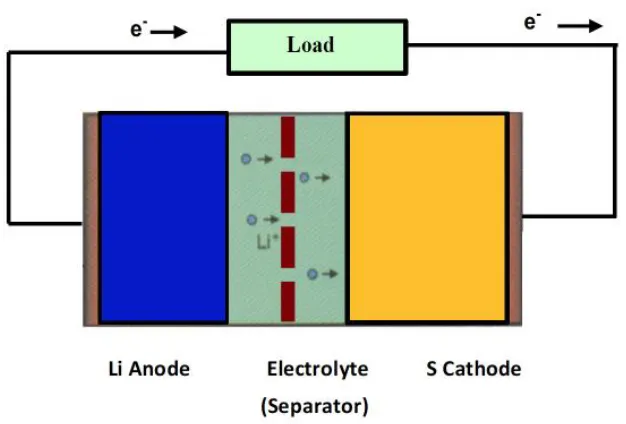
Figure 1.1 A typical structure of Li-S batteries. ... 3
Figure 1.2 Voltage profiles of Li-S cell.1 ... 4
Figure 1.3 (a) Schematic configuration of Li-S cells with coated PP separators. Photographs of (b) bare PP separator and (c) super P coated separator. SEM images of (d) pristine separator and (e) super P coated separator.14 ... 9
Figure 1.4 Cycling performance of Li-S cells with different materials coating on separators.14 . 9 Figure 1.5 Schematic configurations of different Li-S batteries.16 ... 10
Figure 1.6 Cycling performance of Li-S cell with ion-selective membrane.16 ... 11
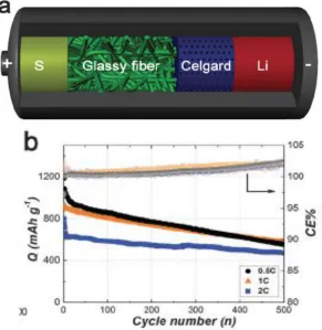
Figure 1.7 (a) Schematic cell configuration of Li-S cell with hybrid separator. (b) Cycling performance of Li-S cell with the hybrid separators.17-18 ... 13
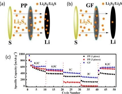
Figure 1.8 Schematic illustration of Li-S cell with (a) PP and (b) GF separator, showing the excellent ability of GF in blocking polysulfides. (c) Rate capabilities of Li-S cell with GF separator.19 ... 14
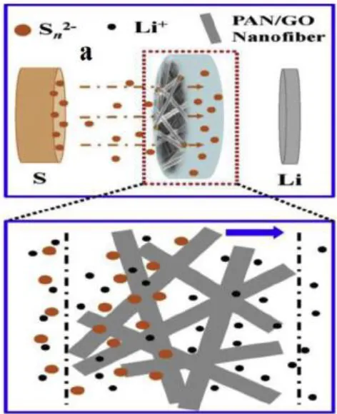
Figure 1.9 Schematic illustration of the Li-S cell with PAN/GO separator.24 ... 16
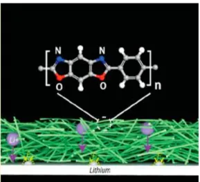
Figure 1.10 Schematic illustration of polyoxyzole nanofiber membrane.25 ... 17
Figure 1.11 Chemical structures of extensively studied polymers for solid electrolytes.31 ... 20
Figure 1.12 (a) Li ion motion in a PEO polymer host. (b) Mechanisms of Li-ion transfer in crystalline domains of polymer matrix.37-38 ... 21
Figure 1.13 Schematic model of these two liquids in PEO/PMMA electrolyte system.41 ... 25
Figure 1.14 Chemical structure of triblock copolymer of P(STFSILi)-PEO-P(STFSILi).42 ... 26 Figure 1.15 (a) Plots of conductivity at various temperatures of several
P(STFSILi)-PEO-xii P(STFSILi) with 31% P(STFSILi) at 40 C. (c) Electrochemical stability
window tested at 80 C.42 ... 27 Figure 1.16 Chemical structure of crosslinked PE/PEO electrolyte with the LiTFSI salt.43 ... 28 Figure 1.17 Schematic illustration of the procedure of in-situ synthesis and the interaction
mechanisms between SiO2 nanoparticles and PEO chains.50 ... 30 Figure 1.18 Schematic of 3D LLZO/PEO solid composite electrolyte.32 ... 31 Figure 1.19 Schematic illustration of the one-pot synthesis of the mixed conducting Li2S
cathode.27 ... 34 Figure 3.1 Plain-view SEM images and corresponding C and O mapping of (a, c, e)
GF/rGO-1, and (b, d, f) GF/rGO-2 separators. Cross-sectional SEM images of (g) GF/rGO-1, (h) GF/rGO-2 separators. ... 47 Figure 3.2 (a) XRD patterns and (b) N2 isothermal adsorption curves of rGO-1 and rGO-2.
XPS spectra of (c) rGO-1 and (d) rGO-2. ... 49 Figure 3.3 (a) EIS curves of fresh Li-S cells with GF, GF/rGO-1 and GF/rGO-2 separators.
CV curves of Li-S cells with (b) GF, (c) GF/rGO-1 and (d) GF/rGO-2 separators at a scan rate of 0.1 mV s-1. ... 51 Figure 3.4 Discharge-charge profiles of Li-S cells with (a) GF, (b) GF/rGO-1 and (c)
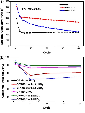
GF/rGO-2 separators tested with electrolyte without the LiNO3 additive. ... 53 Figure 3.5 (a) Cycle performance of Li-S cells with GF, GF/rGO-1 and GF/rGO-2 separators
xiii Figure 3.6 (a) Cycling performance of the Li-S cells with GF, GF/rGO-1 and GF/rGO-2
separators with LiNO3 additive at current density of 0.2C. (b) Rate capabilities of the Li-S cells with GF, GF/rGO-1 and GF/rGO-2 separators with LiNO3 additive. ... 58 Figure 3.7 SEM images of the cycled separators towards Li anode: (a) GF, (b) GF/rGO-1,
(c) GF/rGO-2. Corresponding S mapping (d, e, f) of (a), (b) and (c), respectively. ... 60 Figure 3.8 Photo images of (a) blank electrolyte and (b) polysulfide diffusion model with
GF, GF/rGO-1 and GF/rGO-2 separators after 30 min. ... 61 Figure 4.1 SEM images of (a, b) PP membrane, (c, d) PVDF nanofiber membrane, (e)
rGO-PVDF nanofiber composite membrane, and (f) rGO powder. ... 72 Figure 4.2 Cross-sectional FESEM images of double-layer rGO-PVDF/PVDF separators
with clear demonstration of PVDF and PVDF membrane layers: (a) rGO-PVDF/PVDF-1; (b) rGO-PVDF/PVDF-2. ... 74 Figure 4.3 (a) Nitrogen adsorption-desorption isotherms of rGO powders. (b) BJH pore-
size distributions of rGO powders. ... 75 Figure 4.4 (a) XRD patterns and (b) FTIR spectra of the rGO powder, and PVDF,
rGO-PVDF/PVDF-1 and rGO-PVDF/PVDF-2 nanofiber separators. ... 77 Figure 4.5 Photographs of PP, PVDF, rGO-PVDF/PVDF-1 and rGO-PVDF/PVDF-2
separators (a) before and (b) after thermal treatment (dried after thermal
treatment in liquid electrolyte at 80 C for 24 h). ... 79
Figure 4.6 Nyquist plots of Li-S cells with PP, PVDF, PVDF/PVDF-1 and
xiv Figure 4.7 Galvanic discharge-charge curves of Li-S cells with (a) PP, (b) PVDF,
(c) rGO-PVDF/PVDF-1 and (d) rGO-PVDF/PVDF-2 separators. (e) Schematic illustration of bifunctional double-layer rGO-PVDF/PVDF
membrane separator. ... 81 Figure 4.8 CV curves of Li-S cells with (a) PP, (b) PVDF, (c) rGO-PVDF/PVDF-1 and
(d) rGO-PVDF/PVDF-2 separators. ... 83 Figure 4.9 CV curves at scan rates of 0.1, 0.2 and 0.3 mV s-1 of Li-S cells with (a) PP, (b)
PVDF, (c) rGO-PVDF/PVDF-1 and (d) rGO-PVDF/PVDF-2 separators. ... 84 Figure 4.10 Plots of CV peak currents: peak A refers to the cathode reaction of S8 to Li2S4;
peak B refers to the cathodic reaction of Li2S4 to Li2S; and peak C refers to the anodic reaction of Li2S to S8. ... 86 Figure 4.11 (a) Rate capabilities of Li-S cells with PP, PVDF, rGO-PVDF/PVDF-1 and
rGO-PVDF/PVDF-2 separators at current densities of 0.2C, 0.5C, 1C, 2C and 0.2C, respectively. (b) Cycling performance of Li-S cells with PP, PVDF, rGO-PVDF/PVDF-1 and rGO-PVDF/PVDF-2. ... 89 Figure 4.12 SEM images of (a, c) PP and (b, d) rGO-PVDF/PVDF-2 separators towards Li
metal side after 200 cycles at 1C, and (e, f) corresponding S mappings of (a) and (b), respectively. ... 91 Figure 4.13 SEM images of (a) PP and (b) rGO-PVDF/PVDF-2 separators towards Li metal
side after 100 cycles at 1C. ... 92 Figure 4.14 SEM images of Li metal anode surface with (a) PP and (b) rGO-PVDF/PVDF-2
separators after 200 cycles at 1C, (c, d) corresponding S mapping of (a, b),
xv Figure 4.15 Nyquist plots of Li-S cells with PP and rGO-PVDF/PVDF-2 separators before
and after 200 cycles at 1C. ... 95 Figure 5.1 SEM images of as-spun precursor nanofibers (a), LLTO nanofibers after
calcination at (b) 700 C, (c) 800 C and (d) 900 C for 2h. ... 105
Figure 5.2 Diameter distributions and average diameters of (a) as-spun precursor nanofibers, (b) LLTO nanofibers calcined at 700 °C for 2h and (c) LLTO nanofibers calcined at 800 °C for 2h, and (d) LLTO nanofibers calcined at 900°C for 2h. ... 106 Figure 5.3 (a) TGA curves of as-spun precursor nanofibers. (b) XRD patterns of the LLTO
nanofibers calcined at 700, 800 and 900 C for 2h. ... 107
Figure 5.4 (a, b) TEM images of LLTO nanofibers (800 °C) in different magnifications. (c) Corresponding selected area electron diffraction (SAED) patterns. (d) High-resolution TEM (HRTEM) image of an individual LLTO nanofiber. ... 109 Figure 5.5 (a) EIS curve of LLTO plate at room temperature. (b) XRD patterns of the
PEO/LiTFSI/LLTO solid composite electrolytes with different LLTO nanofiber contents. (c) XRD patterns of the PEO/LiTFSI/LLTO solid composite electrolytes without and with 15 wt.% LLTO nanofiber/particle, showing the influence of LLTO morphology on the crystalline phase of PEO. ... 111 Figure 5.6 SEM images of (a) PEO/LiTFSI, (b) PEO/LiTFSI/LLTO 10 wt.%, (c)
PEO/LiTFSI/LLTO 15 wt.%, and (d) PEO/LiTFSI/LLTO 20 wt.% solid
electrolytes… ... 112 Figure 5.7 (a) EIS results of the PEO/LiTFSI/LLTO solid composite electrolytes with
xvi PEO/LiTFSI/LLTO solid composite electrolytes with different LLTO
nanofiber contents at room temperature. ... 116 Figure 5.8 (a) Arrhenius plots of the PEO/LiTFSI/LLTO solid composite electrolytes with
different LLTO contents. (b) EIS result of the PEO/LiTFSI/LLTO particle solid composite electrolyte with 15% LLTO particles at room temperature. (c) Arrhenius plot of the PEO/LiTFSI/LLTO particle solid composite electrolyte with 15% LLTO particles. ... 117 Figure 5.9 Linear Sweep voltammetry curve of PEO/LiTFSI and PEO/LiTFSI/LLTO
15 wt.% solid composite electrolytes. ... 120 Figure 5.10 Voltage profile of the continued lithium plating/stripping cycling of
PEO/LiTFSI/LLTO 15 wt.% solid electrolyte tested at a current density of 0.5 mA cm-2 at 25 °C (Insert: voltage profiles of PEO/LiTFSI/LLTO 15 wt.% solid electrolyte tested at 710 - 720 h). ... 121 Figure 6.1 Schematic illustration of the novel 1D LLTO nanofiber enhanced composite
xvii Figure 6.2 (a) SEM image of CNFs. Diameter distributions and average fiber diameters
of (b) CNFs and (c) CNF/S. ... 133 Figure 6.3 N2 isothermal adsorption curves of CNF (inserted: corresponding pore size
distribution curve). ... 134 Figure 6.4 SEM images of (a) CNF/S, (b) PEO/LLTO solid polymer electrolyte. (c) High
resolution SEM image of PEO/LLTO solid polymer electrolyte with clearly seen LLTO structure. ... 135 Figure 6.5 Cross-sectional SEM images of (d) CNF/S-PEO/LLTO bilayer framework and
(e) high magnification bilayer framework with clearly seen PEO/LLTO solid
polymer electrolyte (thickness of 15 5 µm). (f) Stress-strain curves of CNF, CNF-PEO and CNF-PEO/LLTO (inserted: photo images of CNF/S-PEO/LLTO electrode with bended structure, showing good flexibility) and (g) EDS
mapping of the cross-section of CNF/S-PEO/LLTO bi-layer framework (e). ... 137 Figure 6.6 (a) HRTEM image of single CNF, (b) CNF/S, (c) CNF/S-PEO/LLTO (LLTO
nanofiber attached on PEO coated CNF/S) and (d) LLTO nanofibers with a lattice spacing of 0.27 nm. ... 138 Figure 6.7 (a) STEM images of one representative CNF/S-PEO/LLTO nanofiber and
corresponding elemental mapping of (b) C, (c) S, (d) O, (e) Ti and (f) La. ... 139 Figure 6.8 (a) XRD patterns of CNFs, CNF/S and CNF/S-PEO/LLTO. (b) DSC curves of PEO and PEO/LLTO solid electrolytes. ... 141 Figure 6.9 (a) EIS results of PEO and PEO/LLTO solid polymer electrolytes tested at
xviii Figure 6.10 Voltage profiles of Li plating/striping cycling with a current density of 0.5
mA cm-2 at RT (inserted: voltage profiles of PEO and PEO/LLTO tested at 201-203 cycles-left; voltage profile of PEO/LLTO at 990-1000 cycles-right) ... 145 Figure 6.11 SEM images of the surface of Li anodes from symmetric Li cells,
(a) Li/PEO/Li and (b) Li/(PEO/LLTO)/Li, after 1000 h testing at a current
density of 0.5 mA cm-2 at room temperature. ... 146 Figure 6.12 (a) Cycling performance of ASSLSBs with CNF/S-PEO/LLTO electrode tested
1 1.1 Background and Operating Principles of Lithium-Sulfur Batteries
The increasing use of fossil fuels has inevitably caused environmental pollution issues. People are trying to seek for clean and sustainable energy options. Therefore, clean energy like solar and wind has attracted numerous attention. However, as the solar and wind energy need to be stored before they can be utilized, it is crucial for the development of efficient and effective electrical storage systems.1, 2 Rechargeable batteries are one of the most viable options of the energy storage systems.
Lithium-ion batteries (LIBs), with its high energy and power density, has been widely used in people’s daily life since its commercialization in 1991.3 Tremendous progress has been achieved in portable electronic devices such as cellphones, laptops, etc. Besides, lithium cobalt oxides and graphite have been the dominate electrode materials in LIBs for almost two decades, because of their relatively high energy/power density and stable cycling performance.2 To improve the energy density of LIBs, advanced composite electrodes like silicon-based anode materials have received intensive research attention nowadays as they have much higher capacities than traditional electrode materials. However, due to the continuously increasing demand for high-energy density batteries in large-scale applications like e-bikes and electrical vehicles (EVs), LIBs finally reach their bottleneck, which is because of the inherent chemistry limitations of those simple insertion-compound electrodes.4 Therefore, materials that can accommodate more electrons and ions would be the prioritized choice for the further increase in energy density of rechargeable batteries.1
2 With this perspective, elemental sulfur (S), one of the most abundant element in earth’s crust, is a perspective electrode material candidate as it has a high theoretical capacity of 1675 mAh g-1, which is nearly one magnitude higher than those of the insertion-compound electrodes of LIBs.1, 5-6 Figure 1.1 shows the structure of a typical lithium-sulfur battery, which consists of S cathode, lithium metal anode and the separator/electrolyte between them. As S is in the charged state, the cell starts with the discharge reaction, in which Li metal is oxidized and produces Li ions with electrons at the negative electrode. The as-generated Li ions in the negative side can diffuse through the electrolyte internally to the positive electrode while the electrons travel by the external electrical circuit to the positive electrode. The elemental S undergoes multistep electrochemical reactions to form lithium sulfides by accepting Li ions and electrons in the positive electrode during discharge and this process can be divided into 4 regions as listed below.1-2, 5-6
Region 1: A solid-liquid reduction from S to long-chain Li2S8.
𝑆8 + 2𝐿𝑖 → 𝐿𝑖2𝑆8 (1.1)
Region 2: A liquid-liquid reduction from long-chain Li2S8 to low-order polysulfides (Li2Sx, 4 x
8).
𝐿𝑖2𝑆8+ 2𝐿𝑖 → 𝐿𝑖2𝑆8−𝑥 + 𝐿𝑖2𝑆𝑥 (1.2)
Region 3: A liquid-solid reduction from low-order Li2Sx to solid state Li2S2 or Li2S.
2𝐿𝑖2𝑆𝑥+ (2𝑥 − 4)𝐿𝑖 → 𝑥𝐿𝑖2𝑆2 (1.3)
3 Region 4: A solid-solid reduction from Li2S2 to Li2S.
𝐿𝑖2𝑆2+ 2𝐿𝑖 → 2𝐿𝑖2𝑆 (1.5)
In contrast, during the charge process, oxidation reaction happens that lithium sulfides are oxidized to polysulfides and finally to S. Thus, the overall redox reaction could be concluded as:
𝑆8+ 16𝐿𝑖 ↔ 8𝐿𝑖2𝑆8 (1.6)
Figure 1.2 indicates the voltage profiles of a Li-S cell. The average voltage for Li-S cell is around 2.15 V with respect to Li+/Li.1
4 Figure 1.2 Voltage profiles of Li-S cell.1
1.2 Challenges and System Limitations of Lithium-Sulfur Batteries
There are key challenges and system limitations that need to be addressed before the practical application of Li-S cells. In general, the Li-S cells suffer from rapid capacity fading and the practical capacity/cycle life are usually lower than expected.1-2, 5
1.2.1 Insulating Nature of Elemental Sulfur and its Discharge Products
The poor electrical and ionic conductivity of S and its discharge products, i.e. polysulfides and lithium sulfides, remain to be the most challenging issue that hinders the practical application of
5 enhance the active material utilization, carbon-based materials and conducting polymers are applied to combine S in cathode structure designs.7-9 However, even though the electrical conductivity of S cathode could be improved to some degree, the ionic conductivity remains to be low.10-11
1.2.2 Shuttling Effect of Discharge Intermediate – Polysulfides
The use of organic liquid electrolyte in traditional Li-S batteries leads to another prominent challenge, which is the shuttling performance of discharge intermediate – polysulfides. Since the polysulfides is highly soluble in organic electrolyte, it can diffuse through the separator reaching lithium metal anode and reacts with the Li, forming short-chain polysulfides with lithium sulfide (Li2S) deposition. Then the short chain polysulfides can diffuse back to the cathode side and be re-oxidized, thus leading the loss of active material, corrosion of Li anode and low Coulombic efficiency.2, 5-6
1.2.3 Large Volume Change of Sulfur Cathode
6 1.2.4 Safety Issues
Aside from the problems from redox reaction, safety is another important concern that needs to be addressed before the practical application of Li-S batteries. So far, it has been recognized that the electrolyte consists of bis(trifluoromethane)sulfonamide lithium salt (LiTFSI) and lithium nitrite (LiNO3) in the mixture solvent of 1,3-dioxolane (DOL)/1,2-dimethoxymethane (DME) (1:1 by volume) is the most efficient liquid electrolyte for Li-S batteries.11, 13 However, the safety issues originating from the low flashing/boiling point of the organic DOL (flashing point: -2 °C; boiling point: 75°C)/DME (flashing point: -18 °C; boiling point: 42°C) solvent remains to be a big problem, which leads to the inflammability and electrochemical instability of Li-S batteries and severely restricts the practical applications which need higher operating temperatures.13
1.3 Recent Advances in Separators of Traditional Liquid Lithium-Sulfur Batteries
7 utilization/polysulfides diffusion could be significantly improved/minimized, thus leading to stable cycling performance of Li-S cells. Although progressive improvements have been achieved, it is still technically impossible to comprehensively avoid the polysulfide shuttling in Li-S cells with high S concentrations.
In addition to the structure designs of S cathodes, coating the separators with functional layers/inserting effective layers between cathode and anode (interlayers) could be another effective approach to minimizing the shuttling of polysulfides and improve the active material utilization.6, 14 It is well known that the separator also plays a crucial role in batteries. The conventional role of separators is to separate the cathode and the anode to prevent the electrical short circuit while helping transport ions. However, in addition to the traditional role, the coated separators/interlayers could also play a crucial role in relieving the polysulfide diffusion by controlling the negatively-charged S-related species. In this respect, the electrochemical performance of Li-S cells will be largely enhanced with those separator modifications.
In this chapter, the recent advances in the development of separators in traditional liquid Li-S cells are reviewed and discussed. The materials which are used as functional layers are also reviewed in this chapter correspondingly based on the type and morphology.
1.3.1 Modification of Traditional Separators
8 for Li-S batteries should not only have good ionic conductivity (high electrolyte uptake) but also should help mitigate the diffusion of polysulfides.15 Microporous polypropylene (PP) membrane is the most commonly used separator for Li-S battery because of its good chemical stability and mechanical strength. However, the relatively low ionic conductivity and poor performance in trapping polysulfides of PP separator hinder the electrochemical performance of Li-S cells.15
With the aim of addressing the poor performance of PP separator, Yao et al. first tried to coat PP separator with different conductive materials: carbon-based materials that have large surface area and high electrical conductivity; and, metal oxides which have strong binding energy with the
negatively-charged polysulfides.14 The thickness of the coating layers is around 1 m. Figure 1.3 shows the schematic configuration of a Li-S cell with coated separators. It is seen that the functional layers are inserted between the S cathode and separator, acting as a second current collector that offer multiple conducting sites for the trapping and reutilization of polysulfides, which greatly minimized the internal resistance of the cell and significantly improved the active material utilization. Figure 1.4 indicates the cycling performance of Li-S cells with different coating materials. It’s obvious that the conductive carbons, including super P, ketjen carbon and
9 Figure 1.3 (a) Schematic configuration of Li-S cells with coated PP separators. Photographs of (b) bare PP separator and (c) super P coated separator. SEM images of (d) pristine separator and (e) super P coated separator.14
Figure 1.4 Cycling performance of Li-S cells with different material coatings on separators.14
10 the schematic configuration of this effective Li-S cell structure design. For the routine membrane, the polysulfides can diffuse freely between the S cathode and Li anode. On the contrary, for the separator with this ion-selective membrane, the negatively-charged polysulfides is largely restricted between the S cathode and the ion selective membrane, because of the electrostatic force between sulfite anion groups and polysulfides, thus the cycling stability of Li-S cell is significantly improved with a low cyclic capacity decay of 0.08% per cycle over 500 cycles as shown in Figure 1.6.
11 Figure 1.6 Cycling performance of Li-S cell with ion-selective membrane.16
1.3.2 Novel Separators for Lithium-Sulfur Batteries
12 1.3.2.1 Ceramic Glass Fiber (GF) Membrane Separator
Commercial glass fiber membrane is made from borosilicate.17 Compared to microporous PP membrane, it has highly porous structure, good thermal stability and excellent electrolyte wettability. These features make GF membrane quite suitable for use as separators in Li-S batteries.
13 Figure 1.7 (a) Schematic cell configuration of Li-S cell with hybrid separator. (b) Cycling
performance of Li-S cell with the hybrid separators.17-18
14 the cell with GF separator showed a high reversible capacity of 262 mAh g-1 at 2 C, revealing the fast-redox reaction in cell with GF separator.
Figure 1.8 Schematic illustration of Li-S cell with (a) PP and (b) GF separator, showing the excellent ability of GF in blocking polysulfides. (c) Rate capabilities of Li-S cell with GF separator.19
However, even though the improved electrochemical performance with enhanced thermal stability could be achieved in Li-S cells when using GF as separators, the geometric and volumetric energy
density of Li-S cells are often lowed as the GF membrane has a thickness of around 260 m.
(a)
(b)
15 Therefore, it is urgent to seek for separators with appropriate thickness and good electrochemical performance.
1.3.2.2 Electrospun Nanofiber Separators
Recently, electro-spun nanofiber membranes have gained much attention as an alternative approach to replace the traditional PP membrane due to its easy processbility and controllable morphology/size.20-23 Electrospinning is the main technique that use to produce nanofibers. In addition, the as-produced nanofiber membrane usually has a high specific surface area to volume ratio, which could produce sufficient reaction sites for the dissolved polysulfides while at the same time, the empty space between the nanofibers can also accommodate the volume change during cycling.
Zhu et al. fabricated a highly porous polyacrylonitrile/graphene oxide (PAN/GO) nanofiber
membrane separator for Li-S batteries.24 Compared to traditional PP separator, this newly designed composite nanofiber membrane has highly porous structure, better thermal stability and abundant -CN groups (from PAN polymer)/oxygen-containing groups (from GO), which can offer higher
16 cycling performance over 100 cycles with a reversible capacity of 597 mAh g-1, which is 38% higher than cell with PP separator.
Figure 1.9 Schematic illustration of the Li-S cell with PAN/GO separator.24
Hao et al. prepared an extra strong polyoxyzole nanofiber membrane to be used as separator in
batteries.25 The high modulus polymeric nanofibers can be processed to prepare flexible and strong membrane separator, which can prevent the lithium dendrites growth/penetration and meet the safe operation requirement of Li-S batteries. In addition, those membranes can withstand a high temperature up to 600 C with a low ionic resistance during cycling. Moreover, the abundant
17 and the polysulfides), thus the overall electrochemical performance of Li-S cells is significantly enhanced. Figure 1.10 indicates the schematic of this strong/effective polyoxyzole nanofiber membrane.
Figure 1.10 Schematic illustration of polyoxyzole nanofiber membrane.25
1.4 Recent Development of All-Solid-State Lithium-Sulfur Batteries
18 polymers10 and metal oxides26 in S cathode structure design/separator modification, it is still technically impossible to comprehensively avoid the polysulfide shuttle in traditional liquid electrolyte Li-S cells.11 Besides, the safety issues coming from the flammable organic solvent as well as the formed lithium dendrites during repeated cycling are another two main safety obstacles that restrict the development of traditional Li-S cells, despite the merits of high ionic conductivity and excellent wetting ability of liquid electrolyte.26
Replacing the liquid electrolyte with solid electrolyte provides “game-changing” opportunities for the practical application of Li-S batteries as it can lead to consistent improvements in electrochemical performance of Li-S cells with safe operation. However, the crucial challenges from solid electrolyte as well as the poor contact of solid-solid interfaces between electrode and solid electrolyte remain to be tough tasks in all-solid-state Li-S batteries (ASSLSBs).13, 27-28
In this chapter, the recent developments in solid electrolytes and electrodes for all-solid-state Li-S batteries are reviewed and discussed.
1.4.1 Solid Polymer Electrolytes for All-Solid-State Lithium-Sulfur Batteries
1.4.1.1 Brief Introduction of Solid Polymer Electrolytes
29-19 30Among all types of solid electrolytes, solid polymer electrolytes (SPEs) have gained much research attention because of the advantages listed below: i) good mechanical strength of SPEs effectively mitigates the dendrite penetration; ii) the potentially high electrochemical stability window enlarges the operation voltage of cells; iii) the solid state nature of SPEs fundamentally avoids the polysulfide diffusion and lithium dendrite formation; and iv) the easy processibility, good flexibility and low flammability characteristics of SPEs also contribute to the fabrication of flexible and safe ASSLSBs.31-32
20 Figure 1.11 Chemical structures of extensively studied polymers for solid electrolytes.31
1.4.1.2 Mechanism of Ionic Transport in Solid Polymer Electrolytes
In SPEs, the ion transport is mainly related to the segmental motion of polymer chains above glass transition temperature.37 Basically, the segmental motion of chains can create free volumes for the hopping of lithium ions, which are in coordinating with the polar groups. Lithium ions can hop from one site to another coordinating site according to the segmental motion of polymer chains, thus the long-distance transport of ions is realized by continuous hopping under electrical field. Besides, the dissociation ability of the lithium salt in polymer matrix can also be used to determine the number of free ions, which is another crucial affecting factor in ion transport.30, 37
21 structure of PEO can also assist ionic transport. The ionic motion of a lithium ion in a PEO host is displayed in Figure 1.12a.38 On the contrary, the existence of crystalline domains in PEO polymer matrix severely restricts the ion transfer at room temperature because of the low level of segmental motions, as showed in Figure 1.12b.37 To get a high level of segmental mobility, PEO based SPEs is always operated above the melting temperature, where the ionic conductivity strongly increase because of the increased free volume for ion transfer. However, at those temperatures, PEO loses its dimensional stability and becomes a viscous liquid, which is not ideal for the blocking of Li dendrites.37-38
Figure 1.12 (a) Li ion motion in a PEO polymer host. (b) Mechanisms of Li-ion transfer in crystalline domains of polymer matrix.37-38
1.4.1.3 Approaches to Increase the Ionic Conductivity of PEO based SPEs
To suppress the crystallization (increase the ionic conductivity) of PEO, various approaches have been used, including: i) addition of plasticizers into the polymer matrix; ii) forming crosslinked or
22 blocked copolymers to change the structure of PEO; and iii) addition of ceramic fillers into the polymer matrix.32-33, 37-38
Addition of plasticizers into the polymer matrix
In the efforts of increasing room temperature ionic conductivity of PEO polymer electrolyte, various additives are researched. Plasticizers are low molecular weight components such as ionic liquids with large anion salts and small organic solvents such as carbonates, dimethyl and tetra(ethylene glycol) etc.37-38
Kelley et al. found that the adding of low molecular weight PEO into the polymer matrix can decrease the glass translation and melting temperature of the polymer while at the same time, can increase the solubility of crystalline polymer and salt composite.39 Besides, Ito et al. used poly(ethylene glycol) (PEG) as the plasticizer in the PEO/Li salt composite and they observed that the ionic conductivity improves with the increase of PEG content, which could be ascribe to the crystallinity decrease/free volume increase in the system.40
23 liquids in the PEO/PMMA electrolyte system.41 It is seen that the Li ions tend to be solvated strongly with the ethylene oxides and are fixed while it can act as charge carrier in electrolyte with HTMAFSI.
However, even though the crystallinity of the polymer is restricted because of the adding of small molecular/ionic liquid plasticizers, the mechanical strength as well as the electrochemical stability window are always lowered and probably that’s the reason that why all the three literatures mentioned above didn’t give any information about these two properties of SPEs.32-33, 37 Therefore, other approaches need to be considered to improve the ionic conductivity of SPEs without the sacrifice of other merits of SPEs.
Crosslinked or blocked copolymers
To combine the properties of high ionic conductivity and good mechanical strength/large electrochemical stability window in SPEs, crosslinked polymers and blocked copolymers are studied extensively.37-38
24 Bouchet et al. reported single-ion BAB triblock copolymers as a highly efficient electrolyte for lithium-metal batteries.42 Here, the polyanionic block copolymer was comprised with polystyrene segments, which acted as a mechanical support in blocked copolymer. Figure 1.14 shows the chemical structure of the as-synthesized triblock copolymers with the Li ions (donated as P(STFSILi)-PEO-P(STFSILi)). As the polyanionic blocked copolymer electrolytes (A-BCE) was combined with the well-known TFSI anion, it enabled an important delocalization of the negative charge, which could significantly increase the current fraction carried by Li ions into the PEO conducting phase, thus increasing the Li ion transference number in the solid electrolytes. Based on the [EO]/[Li] ratios, different polyanionic/polystyrene/TFSI (PSTFSI)-PEO-PSTFSI triblock copolymers were designed and the ionic conductivity, mechanical strength and electrochemical stability window were tested. The results are demonstrated in Figure 1.15. The as-synthesized P(STFSILi)-PEO-P(STFSILi) triblock copolymer with 20% P(STFSILi) exhibited an excellent
27 Figure 1.15 (a) Plots of conductivity at various temperatures of several
P(STFSILi)-PEO-P(STFSILi). (b) Mechanical performance of copolymer P(STFSILi)-PEO-P(STFSILi) with 31% P(STFSILi) at 40 C. (c) Electrochemical stability window tested at 80 C.42
In addition, crosslinking is another way to suppress the crystallinity of polymer and improve the ionic conductivity of SPEs. Besides, it gives the polymer rubber-like characteristics, which is ideal for mechanical strength enhancement in SPEs.43 Khurana et al. designed a cross-linked electrolyte for lithium-metal batteries, which composed of stiff semi-crystalline polyethylene (PE) chains covalently cross-linked by PEO segments. The PE backbone length between crosslinks and PEO segment lengths can significantly suppress the crystallization of PEO and improve the ionic
(a)
(b)
28 conductivity of SPE, thus a high ionic conductivity of above 10-4 S cm-1 was obtained with exceptional dendrite growth resistance. Figure 1.16 demonstrates the chemical structure of this crosslinked PE/PEO solid polymer electrolyte with LiTFSI salt.43
Figure 1.16 Chemical structure of crosslinked PE/PEO electrolyte with the LiTFSI salt.43
Addition of ceramic fillers
29 significantly contribute to the increase of ionic conductivity by increasing the amorphous region in polymer matrix and improving the conductive interface between fillers and polymers.
Das et al. studied the ion conduction of PEO-LiTFSI polymer electrolyte with the addition of Al2O3 filler.49 It is found that adding the Al2O3 fillers into the PEO matrix can suppress the crystallinity of PEO and a maximum amorphous phase of PEO could be observed with a high ionic conductivity of ~3.3 10-4 S cm-1 when 5 wt.% Al2O3 was added. Except for simply blending ceramic fillers with the polymers, Lin et al. introduced an in-situ synthesis of SiO2 nanoparticles in the PEO matrix.50 Much stronger chemical and mechanical interaction can be observed between the PEO polymer and SiO2 nanoparticles, which consequently suppressed the crystallinity of PEO
and improved the dissociation of Li salt. A high ionic conductivity of 1.2 10-3 at 60 C and 4.4
10-5 S cm-1 at 30 C could be observed. In addition, a large electrochemical stability window up
30 Figure 1.17 Schematic illustration of the procedure of in-situ synthesis and the interaction
mechanisms between SiO2 nanoparticles and PEO chains.50
Moreover, in addition to the nanoparticle fillers which can only provide particle-particle junction in polymer matrix, 1D nanofibers with high aspect ratio can create continuous ionic transport pathways.32 In this respect, Fu et al. developed a 3D Li+-conducting network based on the garnet-type Li6.4La3Zr2Al0.2O12 (LLZO) nanofibers lithium ion conductor. The interconnected LLZO network in PEO polymer matrix can provide a continuous Li+ conducting channels. Figure 1.18 indicates the schematic illustration of this design.32 The incorporation of ceramic LLZO nanofibers as the filler has many advantages as it has a high ionic conductivity of around 10-3 S cm-1, good chemical stability against Li metal, air and moisture. Therefore, as combined advantages of this
31 Figure 1.18 Schematic of 3D LLZO/PEO solid composite electrolyte.32
1.4.2 Solid State Electrolytes Enabled All-Solid-State Lithium-Sulfur Batteries
1.4.2.1 Motivation for All-Solid-State Lithium-Sulfur Batteries
32 researches have been focused on integrating solid electrolyte into Li-S cells to form ASSLSBs.11 The advantages of ASSLSBs lie in the improved safety by using nonflammable inorganic solid electrolyte and the increase of energy density due to the minimized polysulfide shuttle.
1.4.2.2 Challenges of ASSLSBs
The reported electrochemical performance of ASSLSBs are still not comparable with the conventional liquid electrolyte Li-S cells in terms of S utilization and rate performance. The poor performance of ASSLSBs mainly comes from the challenges listed below: i) poor electrical and ionic conductivity of S and its discharge products; ii) low ionic conductivity of solid polymer electrolyte at room temperature; iii) ineffective contact of solid-solid interfaces; and iv) the volumetric expansion of S cathode during lithiation/delithiation.
1.4.2.3 Approaches to Address the Problems in ASSLSBs
33 However, even though the capacity of ASSLSBs could be increased to some extent in the initial several cycles, the long-term cycling performance and the rate capabilities of the as-assembled cells are still not ideal in the previously mentioned study. Therefore, it seems that simply improve the electrical conductivity of the S cathode is not enough for achieving high performance ASSLSBs as the electrochemical redox reactions of active materials also requires for fast facial ion transport of Li+. In this respect, increasing the ionic conductivity of S cathode is essential to improve the overall electrochemical performance of ASSLSBs.
34 Figure 1.19 Schematic illustration of the one-pot synthesis of the mixed conducting Li2S
cathode.27
From the above-reviewed literatures, it can be concluded that the properties of solid polymer electrolytes (e.g. ionic conductivity, electrochemical stability window etc.) and S cathode (balanced conductive matrix), play important potential roles in improving the electrochemical performance of ASSLSBs. Large improvements have been obtained in SPEs and S cathodes with those efforts reviewed above, which open avenues for the future developments in ASSLSBs. However, future work should still be focused on the advanced structural designs of SPEs and cathode with the aim of getting effective combinations of the high performance SPEs and dual-conductive cathodes for operation at room-temperature, which is the crucial part for the practical applications of ASSLSBs in e-bikes or EVs since the mostly reported ASSLSBs in literatures are
35 This dissertation focuses on exploring and designing advanced separators/electrolytes for high-performance liquid/solid electrolyte Li-S batteries, with the aim of improving the electrochemical performance of Li-S cells while enabling the safe operation. The main research topics include:
2.1 Reduced Graphene Oxide Modified Glassfiber Separator for Lithium-Sulfur Batteries
As we all know, the separator plays a crucial role in batteries as it separates the cathode from the anode to avoid electrical short circuit and help transport ions. In addition, as a key component relating to the safe operation in batteries, the separator should also be thermally stable with minimum dimensional change. The ideal separator for Li-S batteries should not only have all the properties mentioned above, but also help suppress the diffusion of polysulfides. Reduced graphene oxide (rGO), with its high electrical conductivity, two-dimensional (2D) winkled structure and appreciate oxygen containing groups, is able to reduce the internal resistance as well as to block the diffusion of polysulfides, thus enhancing the electrical performance of Li-S batteries. Here, rGOs with different reduction degrees were selected and used as the polysulfide inhibitor and were coated onto the glassfiber separators to minimize the shutting of polysulfides. The experimental results indicated that the incorporation of rGO coating with higher reduction degree largely minimized the polysulfide shutting, which was supported by the electrochemical performance of Li-S cells and further confirmed by the surface morphology study of the cycled separator. Therefore, it is demonstrated that this work opens an alternative avenue in rGO selection for high-performance Li-S batteries.
36 2.2 A Novel Bi-functional Double Layer rGO-PVDF/PVDF Nanofiber Membrane for High-Performance Lithium-Sulfur Batteries
Electrospun nanofiber membranes have gained considerable research attention as potential separators for Li-S batteries because of their high specific surface area and high porosity, which demonstrate unparalleled advantages in electrolyte uptake and ion transport. Besides, due to its good wettability, ideal mechanical strength and excellent chemical/thermal stability, polyvinylidene fluoride (PVDF) polymer-based nanofiber membranes have been extensively studied for use in lithium-ion batteries. Here, combining the advantages of micro-porous PVDF nanofiber membranes and highly electrical conducive rGO, we introduced a novel, bi-functional double-layer rGO-PVDF/PVDF membrane for high-performance Li-S batteries. The advantages of this double-layer membrane lies in: i) the porous PVDF nanofiber framework in both rGO-PVDF and rGO-PVDF layer provides good thermal stability and maintains the structural integrity of the separator; and ii) the conductive rGO-PVDF layer serves as the polysulfide inhibitor and ensures the fast transfer of lithium ions. The electrochemical results demonstrate that this new double-layer rGO-PVDF/PVDF composite membrane separator provides a general strategy in dealing with multiple challenges in Li-S batteries.
2.3 Li0.33La0.557TiO3 Ceramic Nanofiber-Enhanced Polyethylene Oxide-based Composite Polymer Electrolyte for All-Solid-State Lithium Batteries
37 the electrochemical performance of Li-S batteries, it is still technically impossible to totally avoid the polysulfide diffusion. In addition, the safety problems originating from the flammable liquid electrolyte as well as the lithium dendrite formation also challenge the practical use of liquid electrolyte Li-S batteries.
Replacing the liquid electrolyte with solid electrolyte is promising for the practical application of Li-S batteries as it can lead to consistent improvements in electrochemical performance of cells with safe operation. Here, a polyethylene oxide (PEO)-based composite solid polymer electrolyte filled with one-dimensional (1D) ceramic Li0.33La0.557TiO3 (LLTO) nanofibers was designed and prepared. The incorporation of LLTO nanofibers in the PEO matrix has significantly decreased the crystallinity of PEO polymer, thus more amorphous region was created for the ion conduction. Besides, the 1D LLTO structure could also provide continuous/fast ionic pathways for the ion conduction. Thus, the as-prepared solid composite electrolyte showed a high ionic conductivity of 2.4 10-4 S cm-1 at room temperature with a large electrochemical stability window up to 5 V vs. Li/Li+ and could satisfy most lithium-based batteries.
2.4 Flexible Electrolyte-Cathode Bilayer Framework with Stabilized Interface for Room-Temperature All-Solid-State Lithium-Sulfur Batteries
38 electrolytes, the insufficient contact between electrolyte/electrode interfaces and the poor electrical/ionic conductivity of S and its discharge products.
39 Abstract
Lithium-sulfur (Li-S) batteries are considered as a promising candidate for large-scale applications such as electrical vehicles (EVs) because of their high theoretical capacity, large energy density and low cost. However, due to the shuttling effect of polysulfides, the continuous capacity fading during cycling remains a substantial bumper for the practical use of Li-S batteries. Here, reduced graphene oxide (rGO) materials with different reduction degrees were used as the polysulfide inhibitor and were coated onto glass fiber separators to minimize the shutting of polysulfides. The influence of reduction degree on the effort of polysulfide rejection was investigated. The incorporation of rGO coating with higher reduction degree largely minimized the polysulfide shuttling, thus the Li-S cells with separators modified with high-reduction degree rGO was able to maintain a capacity of 733 mAh g-1 after 100 cycles and delivered a high capacity of 519 mAh g-1 at 2C, which were 42% and 90% higher than those of cells with separators coated with low-reduction degree rGO. Therefore, it was found that rGO with higher low-reduction degree demonstrated better polysulfide rejection performance than rGO with lower reduction degree. This study provides a promising strategy in the rGO selection for high-performance Li-S batteries.
Keywords: Reduced graphene oxide; Reduction degree; Polysulfides; Lithium-sulfur battery
CHAPTER 3 REDUCED GRAPHENE OXIDE MODIFIED GLASSFIBER
40 3.1 Introduction
Lithium-sulfur (Li-S) batteries have received great attention in the present scenario as an emerging energy storage systems in large scale applications like electrical vehicles (EVs) and electrical grids because of their large gravimetric energy density of 2500 Wh kg-1, since sulfur (S) has an unparalleled theoretical capacity of 1675 mAh g-1.1, 55-56 However, the commercialization of Li-S batteries still has a long way to go because of their short cycle life, which is mainly caused by the severe shuttling effect of soluble reduction intermediate – “polysulfides” (PS).57-59 The initial lithiation of S forms long-chain PS (Li2Sn, 4n8), which are soluble in organic electrolyte and
can penetrate through the separator reaching the lithium (Li) anode side. Subsequently, the long-chain PS can further be lithiated into low-order short long-chain PS (Li2Sn, 1n4) with lithium sulfides
(Li2S/Li2S2) depositing on the Li surface, which leads to continuous capacity fading and low active material utilization.5, 15
41 provided by conductive frameworks in S cathodes, it is still technically impossible to comprehensively avoid the PS diffusion in the cells with high S concentrations.
42 reported that, the flexible and conductive rGO sheet as a current collector in S cathodes or as an interlayer could not only suppress the PS diffusion effectively, but also reduce the large volume changes of S during lithiation/de-lithiation.75-77
43 3.2 Experimental
3.2.1 Preparation of rGO Coated Separators
Two different rGO powders were received from Standard Graphene and their oxygen contents were 15.73% and 37.41%, respectively. They were labeled as rGO-1 and rGO-2. For the fabrication of rGO coated separators, 70 wt% rGO and 30 wt% polyvinylidene fluoride (PVDF,
Solef PVDF-5130, Solvay) were mixed together in N-methyl-2-pyrrolidone (NMP,
Sigma-Aldrich), which were then casted onto the surface of the glassfiber membrane (GF, Whatman)
via doctoral blade. The as-obtained rGO coated GF separators, denoted as 1 and
GF/rGO-2, were kept in the vacuum oven at 60 C overnight to evaporate the solvent.
3.2.2 Structure Characterization
A field-emission scanning electron microscopy (FE-SEM, FEI Verios 460L, USA) with an energy dispersive X-ray spectroscopy (EDS) was used to characterize the surface and cross-sectional morphology of the rGO coated separators. X-ray diffraction (XRD) patterns of rGO-1 and rGO-2 powders were determined by Rigaku D/Max 2400 (Japan) with Cu K radiation (=1.5418 Å) in
44 photoelectron spectroscopy (XPS, SPECS FlexMod, Germany) spectra of rGO-1 and rGO-2 were recorded with Mg K radiation.
3.2.3 Electrode Fabrication and Cell Assembly
The working electrode was fabricated by mixing 70 wt% sulfur (S, Sigma-Aldrich), 20 wt% carbon black (C65, TIMCAL Graphite & Carbon Ltd.) and 10 wt% PVDF in a certain amount of NMP to form a uniform slurry. The mixture slurry was coated onto a carbon coated aluminum foil by doctor blade and dried in a vacuum oven at 60 C overnight. Lithium metal foil was used as the counter
electrode and the electrolyte used here was prepared by mixing 1 M bis(trifluoromethane) sulfonamide lithium (LiTFSI, Aldrich) with/without 0.1 M lithium nitrite (LiNO3, Sigma-Aldrich) in a mixture solvent of 1,2-dimethoxyethane (DME, Sigma-Sigma-Aldrich) and 1,3-dioxolane (DOL, Sigma-Aldrich) (1:1 by volume). Coin-type 2032 Li-S cells with 1 and GF/rGO-2 separators were assembled in argon filled glove box. The S loading was around 0.8-1.1 mg cm -2 and the electrode thickness was around 45-50 µm. The amount of electrolyte in each coin cell was fixed at 40 L per 1 mg S.
3.2.4 Electrochemical Performance Characterization
45 spectroscopy (EIS) tests were performed by Garmy Reference 600 device to reveal the internal resistance of the Li-S cells with different separators in a frequency range from 1 M Hz to 1 Hz at an AC voltage of 10 mV.
Several Li-S cells assembled with different separators were disassembled at the charged state in the argon filled glove box after cycling. The morphology and S mapping of separators toward the Li metal side after cycling were characterized by FESEM with an EDS detector.
3.2.5 Polysulfide Diffusion Test
A 0.1 M Li2S8 solution was prepared by adding S and lithium metal into a blank electrolyte of 1 M LiTFSI with 0.1M LiNO3 in a mixture solvent of 1:1 DME + DOL under stirring at 80 °C for 24 h. For the diffusion test set up, the Li2S8 solution was added to vials with open hole caps, which were then sealed with separators with/without rGO coatings. The vials were immersed upside down in the blank electrolyte, and the photograph of diffusion process after 30 min was taken by a camera.
3.3 Results and Discussion
3.3.1 Morphology and Structure Characterization
46 images of GF/rGO-1 and GF/rGO-2 separators. It is seen that both separators had rough surface with numerous interconnected/overlapped rGO sheets and the rGO-1 showed a more porous surface morphology after drying in vacuum. The corresponding EDS mapping of elemental carbon (C) and oxygen (O) of GF/rGO-1 and GF/rGO-2 separators (top-view), shown in Figures 3.1c-f, demonstrated the uniform distribution of rGO sheets and the existence of C and O elements. As shown in Figures 3.1g and h, the thicknesses of rGO-1 and rGO-2 coatings were fixed at around 22±2 m and the coating density was around 1 mg cm-2 for both samples. Table 3-1 shows the corresponding elemental analysis results of rGO-1 and rGO-2. For both rGO-1 and rGO-2 powders, the elemental oxygen concentrations (15.73 % for rGO-1 and 37.41% for rGO-2) were much lower than their carbon concentrations (83.68% for rGO-1 and 62.05% for rGO-2). In addition, rGO-1 had higher carbon concentration than rGO-2 while rGO-2 had higher oxygen concentration. This indicated that compared with rGO-2, rGO-1 was electrically more conductive with a higher reduction degree. The electrical conductivity measurement results indicated that the electrical conductivities for rGO-1 and rGO-2 were 2.08 and 0.64 S cm-1, respectively.
Table 3-1 Elemental Analysis of rGO-1 and rGO-2.
Sample C (wt.%) H (wt.%) N (wt.%) O (wt.%) Conductivity (S cm-1) rGO-1 83.68 <0.5 0.09 >15.73 2.08
47 Figure 3.1 Plain-view SEM images and corresponding C and O mapping of (a, c, e) GF/rGO-1, and (b, d, f) 2 separators. Cross-sectional SEM images of (g) 1 and (h) GF/rGO-2 separators.
Figure 3.2a shows the X-ray diffraction (XRD) patterns of rGO-1 and rGO-2. The XRD pattern of rGO-1 displayed two broad peaks at 26.2 and 43.7, which could be ascribed to the (002)
diffraction of graphite-layered structure and (100) diffraction of graphite, respectively.80 The interlayer distance obtained from the (002) diffraction of 1 was 3.40 Å. Compared with
rGO-1, rGO-2 indicated only one broad peak at 24.2 and the measured interlayer distance was 3.68 Å.
49 Figure 3.2 (a) XRD patterns and (b) N2 isothermal adsorption curves of rGO-1 and rGO-2. XPS spectra of (c) rGO-1 and (d) rGO-2.
3.3.2 Electrochemical Performance of Li-S Cells
51 facilitated the high rate charge transfer but also provided conductive sites for the reutilization of polysulfides.73
Figure 3.3 (a) EIS curves of fresh Li-S cells with GF, GF/rGO-1 and GF/rGO-2 separators. CV curves of Li-S cells with (b) GF, (c) GF/rGO-1 and (d) GF/rGO-2 separators at a scan rate of 0.1 mV s-1.
52 using the well-known lithium metal surface protection additive of lithium nitrite (LiNO3) salt in the electrolyte.86 Figures 3.4a-c show the discharge-charge profiles of the Li-S cells with GF, GF/rGO-1 and GF/rGO-2 separators. All the cells showed two typical discharge regions (first region: 2.4-2.1 V, representing the formation of long chain polysulfides; second region: 2.1-1.7 V, indicating the conversion of Li2S4 to Li2S2 or Li2S) and one closely packed charge region, which were consistent with the CV plots (Figures 3.3b-d).73, 82 Furthermore, the polarization potential (E), as shown in Figure 3.4a, determined by the voltage difference between the charge and
discharge plateaus (second discharge region), of the bare GF separator based cell was 269 mV, which was further reduced to 118 mV and 217 mV for GF/rGO-1 and GF/rGO-2 cells, respectively, and was inconsistent with the CV curves (Figures 3.3b-d) that the cell with GF/rGO-1 separator had the smallest polarization potential. The reduced polarization potentials for the cells with two rGO coatings probably came from the smaller cell impedances, suggesting the efficient reaction process with smaller internal barriers. It is worth mentioning that the E of the cell with
53 Figure 3.4 Discharge-charge profiles of Li-S cells with (a) GF, (b) GF/rGO-1 and (c) GF/rGO-2 separators tested with electrolyte without the LiNO3 additive.
56 The overcharging behavior of the cells was reduced significantly by adding LiNO3 salt in the conventional electrolyte solution. After using LiNO3-add electrolyte, the coulombic efficiencies of the cells with GF, GF/rGO-1 and GF/rGO-2 separators increased to 95%, 99% and 97%, respectively, after 40 cycles (Figure 3.5b). Once again, the Li-S cells with rGO-1 coated separator showed the highest Coulombic efficiency as a result of the excellent functionality of rGO-1 and this prominent functionality was further demonstrated in the improved cycling performance and rate capabilities of Li-S cells. Figure 3.6a shows the long cycling performance of Li-S cells with three different separators after adding LiNO3 in the electrolyte solution. The initial capacities of the cells with GF, GF/rGO-1 and GF/rGO-2 separators were 1102, 1355 and 1472 mAh g-1, respectively. After 100 cycles, the cell with GF/rGO-1 separator could still deliver a high capacity of 733 mAh g-1, which was 56% higher than the cell with GF separator (470 mAh g-1) and 42% higher than the cell with GF/rGO-2 separator (518 mAh g-1).
59 3.3.3 Evaluation of Polysulfides Rejection
60 Figure 3.7 SEM images of the cycled separators towards Li anode: (a) GF, (b) GF/rGO-1, (c) GF/rGO-2. Corresponding S mapping (d, e, f) of (a), (b) and (c), respectively.
61 electrolyte of 1 M LiTFSI with 0.1M LiNO3 in a mixture solvent of 1:1 DME + DOL (Figure 3.8). It is seen that after 30 min, the blank electrolyte with the bare GF separator changed to dark yellow, indicating that a large amount of polysulfides had penetrated through the GF separator from the vial into the blank electrolyte. However, this phenomenon was alleviated when GF/rGO-1 and GF/rGO-2 separators were used. The electrolyte with GF/rGO-2 separator was light yellow. However, the electrolyte with GF/rGO-1 separator did not show observable color change after 30 min, demonstrating the excellent polysulfide blockage ability of rGO-1 coating. On one hand, the rGO-1 coating has excellent polysulfide blockage ability because of its porous structure/assembly morphology (as shown in Figures 1a and b) and the O containing groups, which offered strong physical and chemical adsorption for the negatively charged polysulfides. On the other hand, the enlarged interlayer spacing in rGO-2 (3.68 Å compared with 3.40 Å of rGO-1) as shown in XRD results may contribute to its better electrolyte wetting to some degree, which enhanced the polysulfide diffusivity. Those results were consistent with the electrochemical performance of Li-S cells and the morphological changes of separators after cycling.
62 3.4 Conclusion