ABSTRACT
WANG, XIN. High Performance Composites Based on Superaligned Carbon Nanotubes. (Under the direction of Professor Yuntian Zhu and Professor Jon-Paul Maria.)
Carbon nanotubes (CNTs) with unique structure and properties are in the vanguard of technological development of the time, and are predicted to be the best candidate as the multifunctional component of the next generation of composite materials. To fully utilize the unique mechanical and physical properties of carbon nanotubes, it is essential to assemble them into macroscopic structures. Thus, this dissertation aims to achieve two main goals: 1) demonstrating the growth of tall, uniform and dense vertically aligned CNT arrays and 2) fabricating CNT composites with ideal structural features and excellent mechanical, thermal and electrical performances, and increasing the understanding of the structure-property relationship in these materials.
Vertically aligned CNT arrays containing a high density of long and aligned nanotubes were successfully grown from chemically-synthesized catalyst Fe3O4 nanoparticles by
chemical vapor deposition. In order to improve the thermal stability of catalyst nanoparticles and preserve their monodisprese sizes at the growth temperature, an ultrathin layer of Al2O3
was coated on the nanoparticles prior to CNT growth. The atomic layer deposited Al2O3
coating served as an encapsulating layer for the catalysts preventing them from agglomeration at the growth temperature, which resulted in highly uniform vertically aligned CNT arrays. The adoption of chemically-synthesized nanoparticles provides opportunity for large-scale synthesis of vertically aligned CNT arrays. In addition, the improved uniformity and quality of the arrays due to the Al2O3 coating will improve their performance in real
world applications.
packing density of nanotubes, high degree of CNT alignment and straightness, and intimate nanotube-matrix integration. The obtained CNT composite films with ~50-55 wt% CNTs exhibited a record high tensile strength (3.8 GPa), high Young’s modulus (293 GPa), electrical conductivity (1230 S/cm) and thermal conductivity (41 W/m·K). This fabrication approach also has potential for large-scale fabrication. This study shows the importance of aligning and straightening CNTs for maximizing composite properties.
Similar phenomena were observed in CNT – thermoplastic polymer composites. The mechanical and electrical properties of CNT/nylon 6,6 composites were improved through reducing nanotube waviness by a drawing and stretching method. The tensile strength, Young’s modulus and electrical conductivity of the 7%-stretched composite showed 191%, 294% and 207% increase, respectively, comparing to the unstretched composite.
High Performance Composites Based on Superaligned Carbon Nanotubes
by Xin Wang
A dissertation submitted to the Graduate Faculty of North Carolina State University
in partial fulfillment of the requirements for the degree of
Doctor of Philosophy Materials Science and Engineering
Raleigh, North Carolina 2012
APPROVED BY:
_______________________________ ______________________________
Yuntian Zhu Jon-Paul Maria
Committee Co-Chair Committee Co-chair
________________________________ ________________________________
Maurice Balik Joseph Tracy
DEDICATION
To my beloved parents and brother for their love and unconditional support
To my fiancé, Jianbang
BIOGRAPHY
Xin Wang was born in Maanshan, China on Feb 2, 1985. She is the daughter of Lijin Wang and Ailing Rong and older sister of Rong Wang.
She attended elementary, middle and high school in a historical town named Dangtu, of Maanshan City. In 2002, she was admitted to Donghua University. During the senior design project she was encouraged by her advisor, Professor Yiping Qiu, to explore scientific adventures in advanced composite materials. She graduated in 2006 with a B.S. in Textile Engineering and a B.A. with Honors in Japanese. Then she continued the study in the field of high performance composites and pursued a Master’s degree under the direction of Professor Yiping Qiu. After graduation in 2008, she began the doctoral program in the Department of Materials Science and Engineering at North Carolina State University. Under the direction of Professor Yuntian Zhu, she was dedicated to promoting advances for carbon nanotube materials. She received her Ph.D degree in Materials Science and Engineering from North Carolina State University in 2012.
ACKNOWLEDGMENTS
I would like to express my deepest gratitude to my advisor, Professor Yuntian Zhu, for his guidance, caring, patience and teaching of the philosophy to do good research. I feel grateful for his financial support and the opportunity to work in this excellent group. I would like to thank my co-advisor, Professor Jon-Paul Maria for guiding me in the research of nano-sized thin film preparation and materials characterization. I would also like to thank the members of committee, Professor Maurice Balik and Professor Joseph Tracy, for their invaluable advice and inputs in my research along the way.
I thank all of those who contributed to my research and allowed me to use their equipment: Dr. Qingwen Li (in China) and Dr. Yoku Inoue (in Japan) for providing drawable superaligned CNT arrays, Peter Krommenhoek for providing nanoparticle catalysts, Peter Lam for providing sapphire substrates and help with leak detection for magnetron sputtering machine, Dr. Brad Busche for help with polymer synthesis setup, Dr. Jon-Paul Maria and Dr. George Rozgonyi for use of their x-ray diffraction equipment, Dr. Tzy-Jiun Luo for use of atomic force microscope, Dr. Jagannadham Kasichainula for use of thermal-electrical property testing facility, Dr. Gregory Parsons and his student, Bo Gong, for use of atomic layer deposition facility, Dr. Jacqueline Krim for use of quartz crystal microbalance, Dr. Russell Gorga for use of dynamic mechanical analysis machine, Drs. Hsin Wang and Wei Cai (Oak Ridge National Lab) for use of their thermal conductivity testing instrument, and Dr. Xiangwu Zhang and his student, Ying Li, for help with battery testing.
TABLE OF CONTENTS
List of Tables……….. ... ix
List of Figures……….……….……...x
Chapter 1 Thesis Introduction ... 1
Chapter 2 Literature Background ... 3
2.1 Carbon Nanotube Structures ... 3
2.2 Carbon Nanotube Properties ... 4
2.3 Carbon Nanotube Synthesis ... 6
2.3.1 General Routes for Carbon Nanotube Synthesis ... 6
2.3.2 Growth of Vertically Aligned Carbon Nanotubes ... 8
2.3.3 Growth of Superaligned Carbon Nanotubes ... 12
2.4 Composite Materials ... 14
2.5 Carbon Nanotube Reinforced Composites ... 18
2.5.1 CNT/Polymer Composites Produced by Dispersing Short Nanotubes ... 18
2.5.2 CNT/Polymer Composites Produced with Buckypapers and Arrays... 19
2.5.3 CNT/Polymer Composites Produced with Superaligned CNTs ... 20
2.6 Motivations and Research Objectives ... 23
Chapter 3 General Experimental Procedure ... 27
3.1 Carbon Nanotube Array Growth ... 27
3.2 Carbon Nanotube Composite Fabrication... 29
3.3 Microstructural Analysis ... 30
3.4 Raman Analysis ... 32
3.5 Tensile Testing for CNT Sheets and Composites ... 32
3.6 Thermal Property Characterization ... 33
Chapter 4 Coating Alumina on Catalytic Iron Oxide Nanoparticles for Synthesizing
Vertically Aligned Carbon Nanotube Arrays ... 37
4.1 Background……….. .. 38
4.2 Experimental ... 39
4.2.1 Iron Oxide Nanoparticle Synthesis and Characterization ... 39
4.2.2 Al2O3 Coating and VACNT Array Growth ... 39
4.3 Results and Discussion... 40
4.3.1 Effect of Alumina Coating on Catalyst Nanoparticles ... 40
4.3.2 Enhanced Property of CNT Array Produced by Coated Nanoparticles ... 44
4.4 Conclusions... 48
Chapter 5 Mechanical and Electrical Property Improvement of Carbon Nanotube/Nylon Composites through Drawing and Stretching ... 49
5.1 Background……….. .. 50
5.2 Experimental ... 51
5.2.1 Rotational Winding CNT Ribbons into Composites ... 51
5.2.2 Locally Heating and Stretching the CNT Composites ... 52
5.2.3 Materials Characterization and Testing ... 53
5.3 Results and Discussion... 53
5.3.1 CNT/Nylon 6,6 Composites and Alignment Strategy... 53
5.3.2 Mechanical Property ... 57
5.3.3 Fracture Morphology... 62
5.3.4 Electrical Property ... 64
5.4 Conclusions... 64
Chapter 6 Ultrastrong, Stiff and Multifunctional Carbon Nanotube/Bismaleimide Composites ... 65
6.1 Background ... 66
6.2 Experimental ... 67
6.3.1 Fabrication of CNT Composite Films by Stretch-winding Process ... 70
6.3.2 Mechanical Property ... 75
6.3.3 Thermal and Electrical Conductivities ... 79
6.3.4 Structural Property ... 84
6.4 Conclusions... 88
Chapter 7 Length Effect of Carbon Nanotubes on Mechanical, Thermal and Electrical Properties of Bismaleimide Composites... 89
7.1 Background ... 90
7.2 Experimental ... 91
7.3 Results and Discussion... 92
7.3.1 MWNTs Characterization ... 92
7.3.2 Mechanical Property ... 94
7.3.3 Thermal Conductivity ... 98
7.3.4 Electrical Conductivity... 101
7.4 Conclusions... 103
Chapter 8 Conclusions and Future Work ... 104
8.1 Conclusions... 104
8.2 Future Work ... 106
8.2.1 CNT Alignment Examination by X-Ray Diffraction ... 106
8.2.2 Analytical Study of CNT Waviness Dependence of Composite Properties ... 106
8.2.3 CNT-Polymer Interfacial Properties ... 107
8.2.4 Large-Scale Fabrication of CNT composites... 109
8.2.5 CNT Sheets as Electrodes for Energy Storage Devices ... 110
LIST OF TABLES
Table 5.1 Comparison of the mechanical and electrical properties of pristine CNT ribbons, neat nylon 6,6 and aligned CNT/nylon 6,6 composites with different stretch ratios. S stands for stretch. ... 61 Table 6.1 In-plane thermal diffusivity and thermal conductivity for CNT/BMI composites
with different alignment levels. ... 80 Table 7.1 Mechanical properties of CNT/BMI composites produced using CNTs with
different lengths... 97 Table 7.2 CNT structural changes as the growth time increases. ... 97 Table 7.3 Thermal and electrical properties of CNT/BMI composites produced using CNTs
LIST OF FIGURES
Figure 2.1 A graphene sheet rolled up to form a (10, 5) nanotube by connecting the dashed
lines along vector C. ... 4
Figure 2.2 A picture of a 2.5-mm-tall CNT forest grown with water-assisted CVD on a 7-mm by 7-7-mm silicon wafer. ... 7
Figure 2.3 Nucleation and growth of a MWNT from the Fe carbide nanoparticle catalyst on a substrate, where graphene layers are formed on a nanoparticle and then a MWNT is suddenly expelled from the deformed nanoparticle... 10
Figure 2.4 Schematic of Ostwald ripening of catalysts, and the function of the addition of water vapor in stabilizing catalysts during CNT growth... 11
Figure 2.5 a) SEM images of ordinary VACNT array and superaligned CNT array; b) Schematic illustration of the mechanism of drawing CNTs continuously from superaligned CNT arrays; c) An image of wide (8 inch) CNT sheet being drawn out from superaligned CNT arrays. ... 12
Figure 2.6 Schematic of the “domino pushing” method for producing aligned buckypaper..19
Figure 2.7 SEM images of CNT fibers drawn from a superaligned CNT array... 21
Figure 2.8 Schematic view of spray winding process. ... 22
Figure 2.9 Schematic drawing of a wavy CNT embedded in a composite. ... 24
Figure 2.10 Young’s modulus of CNT composites as a function of CNT waviness. ... 25
Figure 3.1 Schematic of the CVD system designed for growing CNT arrays. ... 28
Figure 3.2 Photograph of the CVD experimental setup built for growing CNT arrays. ... 28
Figure 3.3 Photograph of a fabricated CNT/BMI composite prepreg... 30
Figure 3.4 AFM image of an annealed Fe/Mo catalyst sample used for CNT growth. ... 31
Figure 3.5 Tensile test coupons cut from a composite sheet. ... 33
Figure 3.7 Linear region in the amplitude decay and the phase shift used for eliminating the effects of heat loss. ... 35 Figure 3.8 Test coupons with sputtered Cu electrodes ready for four-probe electrical
resistance measurement. ... 36 Figure 4.1 Schematic representation of Al2O3 ALD coating on monodispersed NPs. ... 41 Figure 4.2 (a) TEM image of the as-synthesized Fe3O4 NPs; AFM images of (b) Fe3O4 NPs
with Al2O3 ALD coating and (c) bare NPs, after annealing for 10 min under H2/Ar atmosphere from room temperature to 750 C. ... 43 Figure 4.3 SEM images of top views of VACNT arrays grown from the (a) Al2O3-coated
NPs and (b) bare NPs with 40 min growth, and side views of the CNT arrays grown from the (c) Al2O3-coated NPs and (d) bare NPs with 40 min growth. Further magnified SEM images of cross sections of the CNT arrays grown from (e) Al2O3-coated NPs and from (f) bare NPs. ... 45 Figure 4.4 TEM images of CNTs grown from the (a) Al2O3-coated NPs and (b) bare NPs.
Corresponding histograms of the CNT diameters, measured from TEM images acquired for at least 30 nanotubes in each sample, are plotted in (c) and (d),
respectively. ... 46 Figure 4.5 (a) Comparison of Raman spectra of VACNT arrays produced by Al2O3-coated
NPs and bare NPs. (b) Plots of maximum height (histogram) of CNT arrays grown by Al2O3-coated NPs and bare NPs, as a function of time. The dotted line indicates excellent curve fitting of the experimental data to Iijima’s growth
equation. ... 48 Figure 5.1 (a) Rotary winding device. (b) A schematic of the drawing and winding process.
The nylon solution was added on the as-wound ribbons using a dropper. (c) A piece of copper wire attached to a heating device provided local heating of the CNT composite. (d) A schematic of the local heating and stretching process. ... 52 Figure 5.2 Raman spectrum of the CNTs prepared by one-step CVD method and used to
make CNT composite in this study. The inset is a TEM image of a thick -walled CNT that was used in this study. ... 54 Figure 5.3 A photograph of the flexible CNT/nylon 6,6 composite film (before stretching)
made by the drawing and winding method. ... 54 Figure 5.4 SEM images of (a) as-drawn CNT dry ribbon showing wavy nanotubes, (b)
CNT/nylon 6,6 composites showing wavy nanotubes, and CNT/nylon 6,6 composite after stretching with differenct ratios: (d) stretched for 2%, (e) stretched for 4% and (f) stretched for 7%. The polymer was removed during TGA. ... 56 Figure 5.5 DSC curves of a non-stretched CNT/nylon 6,6 composite and a composite
stretched by heated-drawing. ... 59 Figure 5.6 Enhanced mechanical properties of CNT/nylon 6,6 composites. (a) Typical
tress-strain curves of the stretched CNT/nylon 6,6 composites, prestine CNT ribbon and neat polymer, illustrating significant improvent of strength and modulus through stretching. (b) Comparison of tensile strength and Young’s modulus of the CNT/nylon 6,6 composites with different stretch ratios. ... 60 Figure 5.7 SEM images of (a) the fracture surface of the CNT/nylon 6,6 composite stretched
for 7%, (b) fractured sheath-core tips of the MWNTs, side views of a stretched composite (c) before hot-pressing (d) after hot-pressing and top views of a
stretched composite (e) before hot-pressing (f) after hot-pressing. ... 63 Figure 6.1 a) SEM image of the as-drawn CNTs from a free-standing CNT array. b) A
high-resolution TEM image of the carbon nanotube. ... 69 Figure 6.2 The experimental setup of stretch-winding process. ... 70 Figure 6.3 a) Schematic illustration of the concept of straightening CNTs before embedding
them in polymer matrix in a layer-by-layer fashion. b) Schematic illustration of the experimental setup for the stretch-winding process. ... 71 Figure 6.4 TGA curves of stretch-winding CNT/BMI composite fabricated with 1g/L
polymer solution, neat BMI and pristine CNTs. ... 74 Figure 6.5 Optical photographs of the CNT/BMI composite films synthesized by
stretch-winding. (a) A twisted CNT composite sheet. (b) Test specimens of CNT
composites fabricated by the stretch-winding approach. (c) A textile woven from CNT composite films. (d) The CNT composite films as segments of conductive media loaded with a LED light bulb... 75 Figure 6.6 a) Comparison of the tensile strength and Young’s Modulus of currently available
Figure 6.7 a) Typical stress-strain curves of pristine CNT sheet, unstretched and stretched composites, demonstrating a significant improvement of the mechanical
properties through aligning and straightening of CNTs. Effect of stretching on b) tensile strength and Young’s modulus, c) thermal conductivity, and d) electrical conductivity of the composites. ... 78 Figure 6.8 Typical tensile stress-strain curves from multiple test specimens from composite
films stretched by 12%. ... 79 Figure 6.9 Electrical properties of the CNT/BMI films. (a) Typical I-V curve at room
temperature. (b) Temperature dependence of the conductivity of a CNT/BMI film. (c) Fitting of the conductivity data of the CNT/BMI film based on the variable range hopping (VRH) mechanism and (d) tunneling mechanism. Electrical
resistances of aligned CNT/BMI films during the deforming process as a function of (e) bending angle and (f) bent cycle. The tests and deformation were carried out along the CNT alignment direction in the films. ... 82 Figure 6.10 (a) Sample preparation for in situ strain-resistance measurement. (b)
Experimental set-up for in situ strain-resistance measurement. ... 83 Figure 6.11 The electrical resistivity-strain and conductivity–strain sensitivity of a
12%-stretched CNT/BMI composite. ... 84 Figure 6.12 Polarized Raman spectra of the D and G bands from a) an unstretched composite film, and b) a composite film stretched by 12%. SEM images of carbon nanotube alignment in c) an unstretched composite film and d) a composite film stretched by 12%. SEM images of typical fracture morphologies of e) an unstretched
composite film and f) a composite film stretched by 12%... 86 Figure 6.13 Effect of stretch ratio on the CNT alignment degree, which is indicated by the
ratio of the intensity (IG∥/IG⊥) of the G-band in the parallel (0°) configuration to the perpendicular (90°) configuration... 87 Figure 7.1 (a) Superaligned MWNT arrays produced by one-step CVD method. (b) An
Figure 7.4 SEM images of CNT structure in the CNT/BMI composites fabricated using CNTs with different lengths. ... 96 Figure 7.5 TEM images and diameter distribution of CNTs with lengths from 0.65 to 1.3
mm. ... 99 Figure 7.6 Heat conduction mechanisms in CNT/polymer composites containing high
volume fraction of long and aligned nanotubes. ... 100 Figure 7.7 CNT length dependence of thermal diffusivity and corresponding thermal
conductivity of CNT/BMI composites. ... 101 Figure 7.8 CNT length dependence of electrical resistance and conductivity of CNT/BMI
composites. ... 102 Figure 8.1 Finite element model of an infinitely long and wavy CNT embedded in polymer
matrix. ... 108 Figure 8.2 The interaction energy of Epoxy and BMI with the CNT as a function of time. 109 Figure 8.3 Winding machine with horizontally movable base designed to enlarge the width
of CNT composites. ... 110 Figure 8.4 Photograph of superaligned CNT sheet tested as electrode for lithium ion
batteries. ... 111 Figure 8.5 Charge-discharge curves of superaligned CNT sheets. ... 111 Figure 8.6 Cycle performance of superaligned CNT sheets at a constant current rate of 0.05
Chapter 1
Thesis Introduction
Carbon nanotubes (CNTs) have superb mechanical and physical properties that are unsurpassed by any other material synthesized to date. Coupled with their “skinny” size and fiber-like low density, these properties make CNTs promising for a wide spectrum of applications including CNT/polymer composites, high strength CNT ropes/yarns, flexible conductors and electrodes for batteries and supercapacitors. The remarkable properties of CNTs are derived from their ideal structure – carbon atoms constructed into a seamless one-dimensional tube with carbon–carbon bond, which is one of the strongest bonds found in nature. However, despite the worldwide effort, there is no method that can translate this impressive credential to large-scale superstrong CNT materials. This is due to three main reasons: i) The large length-to-diameter ratio of CNTs up to millions makes the properties of CNTs highly anisotropic. Therefore, the nanotubes must be assembled and aligned in one-dimensional conformations so that the anisotropic mechanical and physical properties can be utilized. ii) Individual CNTs have intrinsically wavy structures. The waviness is a critical limiting factor for maximizing the properties of CNTs in mascroscopic assemblies. iii) For high-strength polymer composites, the high aspect ratio of CNTs allows an increased surface area available for interaction with the matrix. However, so far there has been no effective method to individually disperse large volume of long CNTs in the polymer matrix. The goals of this work lie in solving these critical issues simultaneously and harness the superior properties of CNTs realized at the nanoscale for multifunctional components of the next generation composite materials.
Chapter 2
Literature Background
2.1 Carbon Nanotube Structures
Carbon nanotubes (CNTs) are allotropes of carbon, which are molecular in size with a one-dimensional cylindrical shape. Since their identification by Sumio Iijima using a transmission electron microscope (TEM) in 1991 [1], CNTs have generated intense research interest due to their unprecedented mechanical, thermal and electrical properties. In addition, CNTs are as light as polymers and have an extremely high length-to-diameter ratio. These attributes make CNTs ideal for applications in various fields including electronics, aerospace, automotive, chemistry and biomedical engineering, and a test ground for fundamental science [2].
Figure 2.1 A graphene sheet rolled up to form a (10, 5) nanotube by connecting the dashed lines along vector C [3].
Carbon nanotubes are strongly related to other forms of carbon, especially 2D graphene layer and crystalline 3D graphite. There are three possible hybridizations occur in carbon: sp, sp2, and sp3, which lead to different structural arrangements of carbon. The sp bonding gives rise to chain structures, sp2 bonding to planar structures and sp3 bonding to tetrahedral structures. Carbon nanotube and graphene orbitals have sp2 hybridization as in aromatic hydrocarbons. The carbon atoms in graphite are connected as a hexagonal network of sigma bonds with electrons from pi bonds distributed above and below the plane of atoms, which makes the in-plane structure very strong. In addition, the delocalized pi system is responsible for the electrical conductivity of the material.
2.2 Carbon Nanotube Properties
measured Young’s modulus for SWNTs are ~1-2 TPa [4] and for MWNTs are ~1 TPa [5]. Due to the strong covalent bonding, seamless structure and small dimension that leave extremely limited room for stress concentration, nanotubes can accommodate large deformations (12-16%) [6,7] without irreversible atomic rearrangements. In comparison, other graphite materials, such as carbon fiber, are not able to accommodate large external forces (elongation less than 0.8%) due to defects in the structure. Therefore, although the Young’s modulus of carbon fibers is as high as 900 GPa [8], the tensile strength is much lower than that of carbon nanotubes due to their small strain-to-failure. Experimentally measured tensile strength for SWNTs has been reported in the range of 13 to 52 GPa [9] and MWNTs of 11 to 63 GPa [6].
Carbon-based materials display the highest measured thermal conductivity of any known materials at moderate temperatures. The stiff sp3 bonds in diamond result in a high speed of sound, which ensure monocrystalline diamond a high thermal conductivity of 2000 W m-1 K -1
[10]. Constructed with even stronger sp2 bonds, coupled with seamless and atomically perfect graphitic cylinders and a few nanometers in diameter, carbon nanotubes are expected to have higher thermal conductivity than diamond. Thermal conductivity is dominated by phonon transport in carbon nanotubes. Theoretical value of 6600 W m-1 K-1 has been demonstrated for nanotubes [11], suggesting their applications for heat management. Thermal conductivity of MWNTs more than 3000 W m-1 K-1 at room temperature has been experimentally observed [12]. For macroscopic structures or devices, a large number of nanotubes must be assembled in high degree of alignment in order to maximize conductance. However, weak tube-tube coupling, dangling tube ends, misalignment and high density of defects render quenching of phonon modes and thus decrease the thermal conductivity. For example, coupling within MWNT bundles decreases the thermal conductivity to 150 W m-1 K-1 [13].
that nanocrystals in a single-crystalline orientation could be used to catalyze chirality-controlled CNT growth. Most MWNTs are metallic due to statistical probability and restrictions on the relative diameters of the individual tubes. However, measurements of MWNTs usually give a lower conductance than metallic SWNTs. This is because present measurement methods, such as two-probe or four-probe techniques, form contacts only to the outmost wall of the MWNT and thus detect only surface current [15]. Also, the interaction of the tube walls could reduce the conductance [16]. CNTs with exceptional electrical properties provide promise for use as interconnects in nanoelectronic devices and circuits, conductive fillers in composite materials, and electrode materials for energy storage and conversion devices.
2.3 Carbon Nanotube Synthesis
2.3.1 General Routes for Carbon Nanotube Synthesis
The properties of carbon nanotubes and their assemblies are determined by the way they are synthesized and arranged. Therefore, the preparation of high-quality nanotubes in large quantities has been the goal of many research efforts. There are three main methods for CNT synthesis, namely arc discharge, laser ablation and chemical vapor deposition (CVD). Because nanotubes were initially discovered using arc discharge method, this technique has been considered the earliest way to produce CNTs. It involves direct current arc discharging between two electrodes in a helium or argon atmosphere [17] and producing CNTs in the plasma of carbon gas. It is usually performed under reduced pressures of between 50 and 700 mbar. This method can yield highly graphitized nanotubes due to the high process temperature (3000-4000 °C), but requires purification process because of large amount of by-products [18].
targets and electrodes. In addition, both methods are not able to produce ordered structures of CNTs; they only generate tangled nanotubes in powder-like products.
Chemical vapor deposition [20-22] has been considered the most promising way to synthesize large-scale ordered structures of CNTs due to its easy control, low cost and capability to produce vertically aligned CNTs (VACNTs) on substrates. In a typical CVD process of CNT growth, a gaseous carbon precursor is “cracked” into atomic carbon and hydrogen by metal catalysts at relatively low temperatures of ~500-1000 °C, and CNTs are nucleated on the catalyst nanoparticles supported by a substrate. Various types of catalytic nanoparticles have been reported for growing VACNT arrays using CVD, such as Fe, Ni, Co and many other metallic catalysts [23-27]. An individual SWNT as long as 4 cm has been synthesized by CVD using iron as the catalyst [28]. Fast growth of super-dense and vertically aligned single-walled nanotube arrays with heights up to 2.5 millimeters (as shown in Figure 2.2) [29] and multi-walled nanotube arrays up to 4 mm [30] were produced by water-enhanced CVD growth. When the growth parameters reach a precise and optimum condition, superaligned carbon nanotube can be continuously drawn from the array and converted into films and yarns [31-36]. These CNT materials produced by CVD method open up the opportunities to develop many novel applications and materials. Since vertically aligned CNTs and superaligned CNTs are the main interest in this work, we offer a more detailed literature review on this subject in the following section.
2.3.2 Growth of Vertically Aligned Carbon Nanotubes
Vertically aligned CNT arrays grown on flat substrates, where the nanotubes have an orientation perpendicular to the substrates, are an ideal platform for various applications, such as field emitters [37,38], interconnects in electronic devices [39], composites [40] and biomedical scaffolds [41]. The merits of the highly ordered structure are high purity, high quality and unidirectional alignment. The quality of CNTs is determined by many factors such as growth duration [42], carbon precursor [43], growth temperature, feed gas flow rate, carrier gas [44], buffer layer and catalysts.
Carbon-containing compounds have been used as carbon precursors for CVD growth of CNTs, most commonly methane (CH4) [45], ethylene (C2H4) [29,46], acetylene (C2H2) [47,48], carbon monoxide (CO) [49], benzene (C6H6) [50], toluene (C7H8) [51], ethanol (C2H5OH) [52], and ethanol/methanol (CH3OH) mixtures [53,54]. Different carbon precursors require different temperature to break down the C-C or C-H bonds in order to release atomic carbons, which directly affects the operating temperatures of CVD growth of CNTs. For example, CH4 decomposes at very high temperatures (> 900 °C) while C2H2 decomposes at lower temperatures (400-700 °C) [55] over catalyst nanoparticles. Therefore, the growth temperature for CH4 is usually higher than that for C2H2. Although higher temperature and larger feeding rate are beneficial for higher rate of CNT growth, they can nevertheless cause production of amorphous carbon and thus lead to catalyst poisoning. Therefore, clean carbon source such as ethanol has been employed to grow CNTs. Some studies [28,56] attributed the growth of clean SWNTs to OH- radicals in ethanol, which is believed to be able to etch away amorphous carbon during the CNT growth. However, so far there has not been any report on long VACNTs grown by ethanol.
(VLS) growth mechanism [58,59], which was first developed by Wagner and Ellis [60]. Although capturing the essence of CNT growth, it did not elucidate atomistic details such as how graphitic cap nucleates, whether the catalysts are liquid or crystalline, and whether they are carbide or metal during the growth. These controversial issues were not solved until Yoshida and coworkers [61] made in-situ Transmission Electron Microscopy (TEM) observations at atomic scale. They found that nanoparticle catalysts were fluctuating crystalline nanoparticles, which were carbide (Fe3C) when subject to CNT growth. Graphitic shells formed on the fluctuating iron carbide nanoparticles and CNTs were expelled from the deformed nanoparticle, as demonstrated in Figure 2.3. The observations suggest that carbon atoms diffuse through the bulk iron carbide nanoparticles, rather than migrate onto the surface, during the growth of CNTs. The metal-support interactions are found to play a determinant role for the growth mechanism [38].
deposition (ALD). CNT growth by CVD is very sensitive to the type of buffer layer. It has been found that the catalytic behavior, Ostwald ripening, and subsurface diffusion rates of Fe catalyst supported on alumina during VACNT growth are strongly influenced by the porosity of the alumina support [69].
Similar to buffer layer materials, metal catalysts can be prepared by a variety of deposition methods [35,70,71]. The film thickness, composition, deposition rate and deposition pressure are of vital importance for determining the final morphology of catalyst thin film, which in turn influences the CNT growth. In addition to those metal deposition methods, there have been a wealth of studies employing novel catalyst preparation techniques such as nanoparticle spin-coating [72], dip-coating [73] and sol-gel [74]. Usually silicon, quartz and glass are used as substrates for growing VACNTs, and recent studies have demonstrated that growth can be achieved on bulk metals, such as stainless steel foils, without the need of additional metal catalyst [75,76]. Among all these methods, fast preparation of large-scale metal catalysts for effective growth of high-quality VACNTs is promising for industrial applications and thus has been the goal for many research groups.
Thermal stability of metal nanoparticles is a crucial factor for sustained growth of VACNTs. As mentioned earlier, agglomeration of metal nanoparticles due to Ostwald ripening will hinder the uniform growth of VACNTs. There has been extensive effort to improve the thermal stability of catalyst nanoparticles. Adding water to the growth process of carbon nanotube carpets was found to inhibit Ostwald ripening due to the ability of oxygen and hydroxyl groups to reduce diffusion rates of catalyst atoms [77]. The proposed mechanism is illustrated in Figure 2.4. Using intermetallic catalyst is another way to enhance the thermal stability of the catalysts due to resultant higher melting point [78] or balanced reactivity [79]. Moreover, various templates such as pre-patterned porous anodic alumina [80] or block copolymer micelles [81] were adopted to prevent the migration and control the size of catalyst nanoparticles.
2.3.3 Growth of Superaligned Carbon Nanotubes
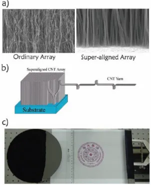
We differentiate superaligned carbon nanotubes from regular VACNTs by recognizing their capability of being continuously drawn from the arrays. SEM images (Figure 2.5a) suggest that superaligned CNT arrays contain better aligned and straighter nanotubes than ordinary VACNTs. Higher degree of alignment is produced due to less amorphous carbon, higher nucleation density for CNTs and narrower size distribution of catalyst nanoparticles.
Top surface entanglement used to be considered as the reason for spinnability of CNT arrays [82]. However, in some study [83] it was proved not the case. Nowadays it is widely accepted that the spinnability stems from the strong van der Waals force between neighboring aligned nanotubes, which allows the CNTs to join end-to-end continuously, as illustrated in Figure 2.5b. A photograph of a spinnable array grown on 8-in wafer is given in Figure 2.5c. Apart from the superaligned structure, clean nanotube surface is considered as another important feature of a spinnable array.
Spinnability of VACNTs can be rated from 0 to 5 with the highest number indicating that continuous sheet can be spun at a speed > 20 m min-1 [84]. Highly spinnable CNT arrays are difficult to achieve because the superaligned structure is extremely sensitive to the precise growth conditions. So far there have been only a few research groups capable to synthesize highly spinnable CNT arrays [31,35,82,85-89]. The precise conditions for growing spinnable arrays fall into a very narrow range that needs to be finely adjusted and combined. The rate of CNT growth is known to increase with temperature or carbon source feeding rate. However, too quick formation of amorphous carbon due to high temperature or high feeding rate smothers the growth and weakens the van der Waal force between nanotubes, which renders the CNTs non-spinnable. Furthermore, it was found that the onset of good spinnability is generally very sharp at the inlet end of the reactor due to optimum gas composition [84]. In addition, catalyst and substrate characteristics play a critical role in growing spinnable arrays, though uniquely different choices may exist. For example, Li et al [35] reported the use of 1 nm iron on 10 nm Al2O3 buffer layer for ethylene growth of spinnable arrays. As for acetylene growth, Zhang et al [82] reported the employment of 5 nm of iron on silicon with ‘native’ oxide of about 5 nm without any treatment, while Jiang et al [31] used 5 nm of iron on silicon with 800 nm thermal silicon oxide, which required annealing, oxidation followed by reduction.
as-drawn sheet, possessing unidirectional mechanical, thermal and electrical properties, which are appealing for fabrication of yarns, polymer composites, optical and electronic devices. Many applications, such as high-strength ropes [34,90], transparent electrodes [91,92], polarizers, flexible touch screens, artificial muscles [32], thermoacoustic loudspeakers [93] and energy storage devices [94] have been demonstrated based on superaligned CNTs.
2.4 Composite Materials
Composite materials can be generally defined as a heterogeneous mixture of two or more distinct components, utilizing the exceptional properties of one component while rectifying shortcomings of the others. Modern fiber-reinforced polymer composites refer to a combination of very strong and stiff fibers within a matrix. The matrix serves as a continuous phase to transfer stress to the reinforcing fibers through their cooperative interaction. They have been developed along with the invention of synthetic fibers in the early 20th century. Carbon nanotubes have unprecedented physical and chemical properties, which no previous material has displayed. They have been considered the most promising candidate for next-generation composite reinforcement.
The physical and mechanical properties of a composite are represented by a rule of mixture for the simplest form:
Pc PfVf PmVm (1)
where Pc represents the composite property and Pf and Pm are the properties of the fibers and matrix, respectively. Vf and Vm are volume fractions of the fibers and matrix, respectively. Vf is usually less than 0.65 because otherwise the composite would contain a large amount of voids produced by current processing technologies.
The volume fraction can be calculated from:
f m f m f f f f W W W V
(2)
or m c f f W V ) 1 ( 1
(3)
where Wf is the weight fraction of the fibers, ρf, ρm and ρc are the densities of the fibers, matrix and composite, respectively.
In a single unidirectional composite prepreg laminate, the elastic modulus in the fiber longitudinal direction E1 is:
E1 EfVf EmVm (4)
The modulus in the transverse direction E2 is:
m f f m m f V E V E E E E
Composite laminate can be laid up to construct laminated composites in order to achieve mechanical properties in multiple loading directions. Off axis mechanical properties of composites can be obtained through using transformation equations [95].
The Halpin-Tsai equations that consider fiber length (L) and diameter (d) are generalized models suitable for the designing of composite materials. For short fiber composite, the parameter ξ in the equations is assumed to have two distinct values, one for the longitudinal (L) (ξ=2L/d) and one for the transverse (T) (ξ=2) directions. The estimated longitudinal and transverse moduli for an aligned fiber composite are:
f L f L m L V V d L E E
1 ) / 2 ( 1 (6) f T f T T V V E
1 2 1 (7) where d L E E E E m f m f L / 2 ) / ( 1 ) / (
, 2 ) / ( 1 ) / ( m f m f T E E E E
(8)The estimated elastic modulus for a random fiber composite is approximated from:
Erandom EL ET 8 5 8
3
(9)
that fails due to a stress application. The interfacial shear strength, τ, can be determined from Kelly-Tyson equation [98]:
c f
L d
2
(10)
For very long aligned fibers (L>~10 Lc), the composite strength is described by:
c (
f
m)Vf
m (11)where σc, σf and σm are the strengths of composite, fiber and matrix, respectively. For mid-length fibers (L>Lc) the composite strength can be described by:
c (
s
f
m)Vf
m (12)where ηs is the strength efficiency factor, equal to (1-Lc/2L). For short length fibers (L<Lc), the composite strength is thus described by:
c (
L/D
m)Vf
m (13)2.5 Carbon Nanotube Reinforced Composites
2.5.1 CNT/Polymer Composites Produced by Dispersing Short Nanotubes
The most common method for preparing CNT/polymer composites is dispersing short CNTs in polymer with a suitable solvent and energetically agitating the solution. Then composite films are formed after solvent evaporation. There are three major characteristics for the short nanotube dispersion method. Firstly, this method is relied on the efficient dispersion of CNTs, and usually produces composites with low CNT volume factions. In addition, due to the fact that long CNTs tend to agglomerate in polymer solution, which renders non-uniform phases in the structure, short nanotubes are generally utilized in dispersion method. Therefore, this method is important for some electrical or thermal applications such as sensors [99]. For example, Sandler et al. [100] dispersed nanotubes with a length of a few microns in epoxy, and fabricated composites with only 0.1-0.5 vol.% CNTs to achieve percolation. High mass fraction composites can also be fabricated. Shaffer and Windle [101] mixed CNTs with polyvinylalcohol (PVA) and water, and produced composite films with up to 60 wt.% nanotubes. Secondly, pristine short CNTs are difficult to be well-dispersed in most solvents. They require surfactant or functionalization agent before mixing with the polymer solution. Both covalent and non-covalent functionalization have been studied for improving the CNT-polymer bonding [102,103]. Thirdly, nanotubes dispersed in polymers have random orientation, which adversely affect the composite properties. Electrostatic force can be used to improve the nanotube alignment, through a self-assembly process [104].
Melt processing is an alternative to solution processing. It is particularly useful for thermoplastic polymers where polymer pellets are melted and CNTs are added by shear mixing. Andrews and co-workers [105] demonstrated that high impact polystyrene, polypropylene and acrylonitrile-butadiene-styrene (ABS) could be melt processed with MWNTs to fabricate composites.
microscale sample size, good alignment and high nanotube fraction. Vigolo and Poulin [106] reported coagulation-spun SWNT/PVA composite fibers with a tensile strength of ~1.5 GPa, a Young’s modulus of ~15 GPa and electrical conductivity of 10 S/cm. Dalton and Baughman [107] reported coagulation-spun high mass fraction (~60 wt%) SWNT/PVA composite fibers with super toughness.
2.5.2 CNT/Polymer Composites Produced with Buckypapers and Arrays
Paper-like CNT film, known as buckypaper, has attracted much attention for the development of CNT composites because of its potential applications in catalysis, filtration, sensors, actuators and electrodes for supercapacitors or lithium ion batteries [108]. Generally the fabrication of buckypaper involves dispersion and filtration of a suspension of CNTs. Recently there have been newly-developed approaches to directly push or print CNT arrays into buckypapers, which feature highly aligned CNTs in planar form. Wang et al. [109] presented a “domino pushing” method for preparing large areas of aligned thick buckypapers from vertically aligned CNT arrays, as shown in Figure 2.6. Similarly, “shear-pressing” [40] and “transfer-printing” [110] approaches were demonstrated to push or roll across the silicon substrate grown with the CNT arrays.
Aligned buckypaper has demonstrated excellent mechanical properties. Cheng and co-workers [111] demonstrated a mechanical stretching strategy for producing high mass fraction (~60 wt.%) MWNT composites with the tensile strength and modulus reaching 2 GPa and 169 GPa, respectively. By functionalizing the buckypaper and infiltrating with aerospace grade bismaleimide resin, they further improved the composite strength and modulus to 3 GPa and 350 GPa, respectively [112]. This is the first report to demonstrate that mechanical properties of CNT composites can exceed the state-of-the-art carbon fiber composites. Apart from the superior mechanical properties, these composites have also shown a high electrical conductivity (5500 S/cm). Nanocomposites made with buckypaper and polycarbonate solution containing 40-60 wt.% CNTs exhibited promising electrical conductivities (>200 S/cm), which are 1.7-3 times higher than that of the neat buckypaper [113]. The electrical properties of the conductive composites would enable them useful for electromagnetic interference shielding, lightning strike protection components and electrostatic discharging in electronic components. Pristine aligned buckypaper has shown a thermal conductivity of ~42 W/m·K [114]. However, high thermal conductivities of buckypaper composites haven’t been realized, which is mainly due to tube coupling, high interfacial thermal resistance and defects that scatter phonons.
2.5.3 CNT/Polymer Composites Produced with Superaligned CNTs
double-walled nanotube fibers having electrical resistivity reaching ~10-7 Ω·m, whose specific electrical conductivity is superior to copper.
CNT fibers synthesized by solid-state drawing possess such characteristics as long CNT length, high purity, high quality, high level of CNT alignment and ordered structure. Such fibers are extremely promising for fabrication of CNT fiber based composites featuring high strength or excellent conductivity. Bogdanovich and Bradford [117-119] conducted pioneered research in textile assemblies of CNTs. They fabricated 3 -D braids and their composites, and demonstrated high in-plane mechanical properties with substantially improved transverse strength, damage tolerance and impact resistance. However, there are two major limitations for developing CNT fiber composites: i) micro-sized sample that is difficult to be commercially applicable, and ii) low production rate.
CNT sheets drawn from the superaligned array can be directly used for fabricating CNT composites. Cheng et al. [120,121] was the first group to utilize solid-state drawn CNT sheets for producing aligned CNT composites. By dry-drawing the CNT sheets and infiltrating them with epoxy resin, they produced composites with 16.5 wt% CNTs that were homogenously dispersed and highly aligned in the epoxy matrix. The Young's modulus and tensile strength of the composites reached 20.4 GPa and 231.5 MPa. Recently, a rotary winding approach (as shown in Figure 2.8) was developed to draw out CNT sheet from superaligned array and simultaneously apply polymer solution onto each layer of CNTs [122,123]. The resultant composites were measured to have a strength of ~1.8 GPa, a modulus of 40-96 GPa, and a toughness of 38-100 J/g. These results demonstrate the advantage of aligned nanotubes, long CNT length and good nanotube dispersion in polymer matrix for fabricating high performance CNT composites.
2.6 Motivations and Research Objectives
Since their discovery in 1991[1], there have been tremendous advances made in scientific research for carbon nanotubes, and this has given impetus to significant technological improvements in the carbon nanotube-based composites. Despite extensive worldwide effort, it has been a challenge for two decades to assemble the extremely strong carbon nanotubes into macroscopic CNT composites that break the strength ceiling of carbon fiber composites. The ideal structures of CNTs in the composites must have long lengths, unidirectional alignment, a high volume fraction and moderate to strong CNT-polymer bonding or interaction. However, most of the composites obtained so far have one or more of the critical structural features missing and thus miss the mark for becoming comparable to carbon fiber composites. Superaligned CNT sheets containing long and aligned nanotubes that are joint end-to-end continuously provide an exciting and promising opportunity to address these challenges. However, so far there have been only a few studies of the composites based on superaligned CNT sheets. Moreover, promising properties of these composites have yet to be demonstrated.
A critical issue limiting the property improvement of the composites is the wavy nanotube on the effective properties of the nanotube-reinforced composites. Figure 2.9 is a schematic drawing of a wavy nanotube embedded in a composite. With the inclusion of CNT waviness, the expression of Young’s modulus for straight fiber reinforced composites is no longer suitable. Therefore, conventional rule of mixture is modified as [124]
Ec cos LVfECNT (1 Vf)Em
2
(14)CNT, we obtain an average alignment factor related to the amplitude and wavelength of the nanotube: 2 2 2 1 1 cos
a (15)where a and λ are the amplitude and wavelength of the CNT, respectively, which can be determined from micrographs. The Young’s modulus of the composite as a function of waviness factor (a/λ) is plotted in Figure 2.10. As expected, the composite stiffness is strongly dependent on the nanotube waviness. It significantly decreases with increasi ng nanotube curvature.
Figure 2.9 Schematic drawing of a wavy CNT embedded in a composite.
composites. The simulation results for CNT waviness dependence of composite stiffness are consistent with our derived analytical model. C Li and co-workers [127] used Monte Carlo simulations and found that the electrical conductivity of composites with wavy nanotubes is much lower than that of composites with straight nanotubes. F Deng et al. [128] used analytical models to predict the impact of nonstraight geometries of the CNTs on the effective thermal properties of CNT composites. They found that CNT waviness is a dominant factor, rather than the lateral interfacial thermal resistance, that limits the improvement of thermal conductivity of composites. However, the effect of CNT waviness on composites produced with long and aligned CNTs has not been investigated.
The objective of this research is to develop a novel approach that utilizes drawable superaligned CNTs, simultaneously realizes all the critical structural characteristics of CNT composites (to a degree) and bypasses the difficulty of functionalization of CNTs. Most importantly, the issue of CNT waviness is to be solved and thus a deeper understanding of structure-property relationship is to be provided. This approach would directly deliver CNT/polymer composites with combined high strength, stiffness and multifunctionalities that are not accessible to current engineering composite materials.
Another opportunity is thus given by the successful development of unidirectional CNT composites composed of long and aligned CNTs. Based on the aligned CNT structure, the length effect at millimeter scale on composite properties will be explored. Our objective is to identify the mechanism how longer CNTs with larger tubular diameter and higher aspect ratio would affect the mechanical, thermal and electrical properties of aligned CNT composites.
Chapter 3
General Experimental Procedure
3.1 Carbon Nanotube Array Growth
Fe3O4 nanoparticles (NPs) with an average diameter of 6 nm were synthesized by a rapid injection method [129]. The NPs were resuspended in hexanes (~1 wt%) and were then spincast on atomic layer deposited (ALD) Al2O3 buffer layer (~10 nm)/Si substrate with an approximate monolayer coverage. ALD coating was carried out in a hot wall viscous flow vacuum reactor equipped with in situ quartz crystal microbalance (QCM) [130]. One hundred cycles of trimethylaluminum/H2O deposit a 10 nm Al2O3 layer on the substrate. The (100) 350 μm-thick polished silicon wafers were purchased from University Wafer Company.
Figure 3.1 Schematic of the CVD system designed for growing CNT arrays.
3.2 Carbon Nanotube Composite Fabrication
Carbon nanotube/nylon 6,6 composites were fabricated with 700 µm-high superaligned carbon nanotubes, which were produced by a one-step CVD method [89] using FeCl2 as catalyst. The CNT arrays were received from Shizuoka University (Japan). The CNTs were drawn from the arrays onto a rotating cylindrical polytetrafluoroethylene (PTFE) spool. The tension created by drawing was able to pre-align the ribbons. As the CNT ribbon was being wound, nylon 6,6 (1.14 g/cm3 at 25 °C, molecular weight=262.35, Sigma Alderich) solution (1 wt. % in phenol) was infused between the CNT layers using a dropper. The as-wound CNT/nylon 6,6 composite was then removed from the PTFE spool. Stretching for CNT/nylon 6,6 composite prepregs was performed on a tensile testing machine (Shimazu EZ-S). The composite was locally heated by a fabricated heating element with dual prongs. The temperature measured by a thermocouple between the two extended wire ends reached 160 °C. The heating element moved along the composite at a speed of 3 mm/s and the composite was stretched by the tensile tester along the length direction at a speed of 0.1 mm/min. The low applied load and the moving local heating source ensured that the whole composite was uniformly stretched without premature failure. The stretched CNT composites were then hot pressed between two glass plates in a vacuum oven at 160 °C for 1 h.
added to the resin system as the initiator. The size of the unidirectional composites can be adjusted by choosing an appropriate CNT sheet width, spool diameter, and number of revolutions. The CNT preform was removed from the PTFE spool and heated in a vacuum oven at 90 °C for 2 h for removing the residual solvent. The uncured preform was cut into strips and hot-pressed between glass blocks coated with a PTFE release agent and cured in a vacuum oven at 180 °C for 2 h. Figure 3.3 shows a 12 mm wide and 70 mm long CNT/BMI composite sheet. The detailed methods for processing CNT/BMI composites with various structures will be discussed in the respective chapters.
Figure 3.3 Photograph of a fabricated CNT/BMI composite prepreg.
3.3 Microstructural Analysis
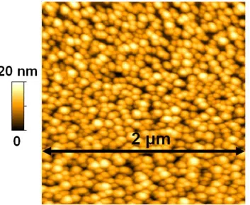
was rotated by 45° and images were taken again after being scanned along a specific axis. Figure 3.4 shows an AFM image of the surface of Fe/Mo catalysts supported by Al2O3/Si substrate, as an example.
Figure 3.4 AFM image of an annealed Fe/Mo catalyst sample used for CNT growth.
Scanning electron microscopy (SEM) images were taken by a JEOL 6400F SEM operating at 5kV. The CNT assemblies were mounted on the stage using conductive carbon tape without the need for sputtering metallic coating as the CNTs are conductive.
pulled out from the array and directly placed on the Cu TEM grid with holey carbon. Water was dropped around the grid in order to allow the CNTs to firmly attach to it and then the samples were allowed to dry.
3.4 Raman Analysis
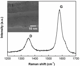
The quality of as-grown CNT arrays was assessed using a Renishaw Ramascope. The laser has a wavelength of 514 nm and a spot size of ~1-2 µm. The laser was focused on the sample through a Renishaw microscope. Samples were scanned in the Raman shift range of 1700-1200 cm-1 that covers the D-band and G-band of CNTs. During acquisition, the samples were scanned for 100 seconds in order to reduce background noise. Each sample was tested at three different locations to ensure the consistency of spectra.
To characterize the degree of CNT alignment, polarized Raman spectroscopy tests were carried out with a LabRam HR800 confocal Ramascope (ORIBA Jobin Yvon Ltd.). A laser with wavelength of 632.81nm was used for excitation. Vertically polarized incident light passed through a notch filter and then scattered within the sample whose alignment axis is rotated to an angle θ with respect to the incident polarization direction. At θ=0°, or when the polarization of the excitation laser’s oscillating electromagnetic field is parallel to the nanotube longitudinal axis, the Raman intensity is maximized. While at θ=90°, the Raman scattering from the SWNTs should display a minimum. The ratio of the intensity of the G-band in the parallel configuration to the perpendicular configuration (IG∥/IG⊥) is particularly sensitive to CNT alignment degree: higher intensity ratio indicates higher CNT alignment degree.
3.5 Tensile Testing for CNT Sheets and Composites
fixed at 6 mm for all measurements. Sample width was measured using a calibrated scale bar in an optical microscope (30 ×). Sample thickness was measured using a micrometer and the error was verified to be within 15% by thickness measurements using SEM. At least five specimens were tested for each type of composite, and were tested at 0.5 mm/min. Strain-to-failure was measured from grip displacement until sample failed. Elastic modulus was calculated from the slope of the initial straight-line loading region.
Figure 3.5 Tensile test coupons cut from a composite sheet.
3.6 Thermal Property Characterization
The in-plane thermal diffusivities of CNT composites were measured by a Laser PIT device (Ulvac-Riko, Inc.) at room temperature and in a vacuum of less than 0.01 Pa (as shown in Figure 3.6). Before testing, the sample was cleaned by ethanol. Then a tiny spot of silver paste was used to attach the sample to the thermocouple. During testing, the scanning laser heating provides a highly uniform and high intensity energy source along the test sample that is 5 mm wide and 25 mm long. An analysis method using both the amplitude decay and the phase shift was adopted to eliminate the effects of heat loss. An example is given in Figure 3.7. The thermal conductivity of the composite was thus calculated from the thermal diffusivity, specific heat capacity, and density of the composite.
Figure 3.7 Linear region in the amplitude decay and the phase shift used for eliminating the effects of heat loss.
3.7 Electrical Property Characterization
Electrical resistance was measured using the four-probe method by a 34410A 6.5 digit multimeter. As shown in Figure 3.8, test coupons were cut into strips and tested along the nanotube alignment direction. To ensure good electrical contact, copper was coated as electrodes on the specimen using a magnetron sputtering facility.
Chapter 4
Coating
Alumina
on
Catalytic
Iron
Oxide
Nanoparticles for Synthesizing Vertically Aligned Carbon
Nanotube Arrays
Xin Wang1, Peter J. Krommenhoek1, Philip D. Bradford2, Bo Gong3, Joseph B. Tracy1, Gregory N Parsons3, Tzy-Jiun M. Luo1, Yuntian T. Zhu1
1 Department of Material Science and Engineering, North Carolina State University; 2 Department of Textile Engineering Chemistry and Science, North Carolina State
University; 3 Department of Chemical and Biomolecular Engineering, North Carolina State University.
ABSTRACT: To synthesize long and uniform vertically aligned carbon nanotube (VACNT) arrays, it is essential to use catalytic nanoparticles (NPs) with monodisperse sizes and to avoid NP agglomeration at the growth temperature. In this work, VACNT arrays were grown on chemically-synthesized Fe3O4 NPs of diameter 6 nm by chemical vapor deposition.
Coating the NPs with a thin layer of Al2O3 prior to CNT growth preserves the monodisperse
sizes, resulting in uniform, thick and dense VACNT arrays. Comparison with uncoated NPs shows that the Al2O3 coating effectively prevents the catalyst NPs from sintering and
coalescing, resulting in improved control over VACNT growth.
4.1 Background
The unique structural, mechanical, electrical and thermal properties of carbon nanotubes (CNTs) have made them appealing for a wide range of scientific exploration and applications. Vertically aligned carbon nanotube (VACNT) arrays are ordered structures of CNTs where the nanotubes are oriented parallel to each other and perpendicular to a substrate. VACNT arrays containing a high density of long aligned CNTs have been used as building blocks of high-specific-strength fibers [33], composites [40], energy-absorbing foams [131,132], and biomimetic scaffolds [41]. VACNTs are usually grown by chemical vapor deposition (CVD) on substrate-supported metal nanoparticles (NPs). Various types of catalytic NPs have been reported for growing VACNT arrays using CVD. Recently ligand-stabilized NPs, such as Fe, Ni, Co, have attracted extensive research interest [133]. In addition to their novel magnetic properties [134-136], these NPs have been successfully used as catalysts for CNT growth [137,138] and carbon nanofiber growth [139].
In this work, we report the stabilization of monodisperse Fe3O4 NPs with Al2O3 by ALD,
which resulted in the synthesis of long VACNT arrays with a high degree of uniformity. Our results revealed significant effects of the Al2O3 coating on the size distribution, activity and
lifetime of the Fe3O4 NPs. The ultrathin Al2O3 layer encapsulating the NPs prohibited their
agglomeration at high temperatures, resulting in long, uniform, and dense VACNT arrays. Under the same conditions, the bare NPs fused into large particles and formed large areas of particle clusters, which catalyzed the growth of short, non-uniform and low-density CNT arrays.
4.2 Experimental
4.2.1 Iron Oxide Nanoparticle Synthesis and Characterization
Fe3O4 NPs with an average diameter of 6 nm were synthesized using a method reported by Woo, et al [129]. 400 μL (3.04 mmol) of Fe(CO)5 (99.5%, Alfa Aesar) was rapidly injected into a solution containing 0.96 mL (3.04 mmol) oleic acid (99%, Alfa Aesar) and 20 mL of octyl ether (TCI America) in a 100 mL three-necked, round-bottomed flask at 100 °C under nitrogen flow. The solution was then slowly heated and refluxed for two hours at ~300 °C. Upon cooling, ethanol was added (1 mL per mL of NP growth solution), and the NPs were isolated by centrifugation. The NPs were resuspended in hexanes (~1 wt %) and were then spincast on ALD Al2O3 buffer layer (~10 nm)/Si substrate with an approximate monolayer coverage [146]. Transmission electron microscopy (TEM) images of the NPs dropcast onto a Cu TEM grid with the amorphous carbon and Formvar supports were acquired using a JEOL 2000FX TEM operated at 200 kV. The NP sizes were measured using the ImageJ software. For each NP sample, the diameter and standard deviation were determined by averaging measurements of 100 NPs.
4.2.2 Al2O3 Coating and VACNT Array Growth
Fe3O4 NPs with and without Al2O3 coating were placed at equivalent positions in the same CVD furnace during the same run. After loading the catalysts, the growth tube was evacuated to 25 Torr and refilled with a mixture of flowing H2 (10 standard cubic centimeters per minute, sccm) and Ar (65 sccm). The furnace was heated to 750 C in approximately 10 min. The carbon precursor, ethylene (C2H4), was introduced into the growth tube at a flow rate of 15 sccm once the furnace reached 750 C, which marked the beginning of the growth time. A series of identical catalyst samples were used to grow VACNT arrays with growth times of 5, 10, 20, 30 and 40 min. The array height was measured using a calibrated scale bar in an optical microscope (30×). The morphology of the CNT arrays was investigated using a field emission scanning electron microscope (FE-SEM) (JEOL 6400) operated at 5 kV, and the quality of the VACNT arrays was examined by a Renishaw Raman spectrometer using a 514 nm laser. To characterize the pregrowth process, samples of Fe3O4 NPs with and without the Al2O3 coating were exposed to the CNT growth environment in the absence of C2H4. The samples were cooled to room temperature immediately after reaching 750 C. The annealed samples were then imaged by atomic force microscopy (AFM, Veeco Caliber) using silicon nanoprobe cantilevers as scanning probes. The noncontact scanning mode was used to collect images at a voltage set point of 2.8 V and a scan rate of 0.5-1 Hz.
4.3 Results and Discussion
4.3.1 Effect of Alumina Coating on Catalyst Nanoparticles
The process for stabilizing NPs by coating with Al2O3 throughALD is depicted in Figure
4.1. During spincasting, the ligands keep the NPs well separated and prevent agglomeration of the NP cores, which have average diameters of 6 nm, as shown in Figure 4.2a. After ligand removal from the catalyst NPs by ultraviolet light and ozone (UVO) for 5 min, ALD of an amorphous, 1 nm-thick layer of Al2O3 provided a significant barrier to mobility of the
underlying NPs. Conformal Al2O3 coatings produced by ALD have been found to fully
the Al2O3 is deposited, on top of the NPs, on the buffer layer supporting the NPs, and within
the gaps between NPs.
![Figure 2.1 A graphene sheet rolled up to form a (10, 5) nanotube by connecting the dashed lines along vector C [3]](https://thumb-us.123doks.com/thumbv2/123dok_us/1490360.1182359/21.612.135.495.75.302/figure-graphene-sheet-rolled-nanotube-connecting-dashed-vector.webp)
![Figure 2.3 Nucleation and growth of a MWNT from the Fe carbide nanoparticle catalyst on a substrate, where graphene layers are formed on a nanoparticle and then a MWNT is suddenly expelled from the deformed nanoparticle [61]](https://thumb-us.123doks.com/thumbv2/123dok_us/1490360.1182359/27.612.131.499.410.620/nucleation-nanoparticle-substrate-graphene-nanoparticle-expelled-deformed-nanoparticle.webp)
![Figure 2.4 Schematic of Ostwald ripening of catalysts, and the function of the addition of water vapor in stabilizing catalysts during CNT growth [77]](https://thumb-us.123doks.com/thumbv2/123dok_us/1490360.1182359/28.612.109.522.357.616/schematic-ostwald-ripening-catalysts-function-addition-stabilizing-catalysts.webp)
![Figure 2.7 SEM images of CNT fibers drawn from a superaligned CNT array [34].](https://thumb-us.123doks.com/thumbv2/123dok_us/1490360.1182359/38.612.169.462.339.633/figure-sem-images-cnt-fibers-drawn-superaligned-array.webp)