Copyright to IJIRSET www.ijirset.com 800 ISSN (Online) : 2319 - 8753
ISSN (Print) : 2347 - 6710
I
nternationalJ
ournal ofI
nnovativeR
esearch inS
cience,E
ngineering andT
echnology An ISO 3297: 2007 Certified Organization, Volume 2, Special Issue 1, December 2013Proceedings of International Conference on Energy and Environment-2013 (ICEE 2013)
On 12th to 14th December Organized by
Department of Civil Engineering and Mechanical Engineering of Rajiv Gandhi Institute of Technology, Kottayam, Kerala, India
NUMERICAL SIMULATION OF FLOW THROUGH MINI
CHANNELS WITH INTERNAL
OBSTRUCTIONS
Midhun. P, Rahul H Kumar, K.S.Santhosh
Assistant Professor, Department of Mechanical Engg., Vidya Academy of Science and Technology, Kilimanoor, Kerala, India
PG student, Department of Mechanical Engg College of Engineering Trivandrum, India Assistant Professor, Department of Mechanical Engg College of Engineering Trivandrum, India
ABSTRACT
This paper presents the simulations of turbulent flow with heat transfer through channels with surfaces of complex configurations like wavy, triangular and rectangular ribbed walls using the open source CFD code OpenFOAM. The simulations were carried out using low Re k-ε turbulence model. OpenFOAM simulations predicted the flow structure and temperature distribution near the wavy wall, moreover the critical amplitude of the wavy wall, where the heat transfer is maximum.
NOMENCLATURE
H channel height (m) L channel length (m)
am amplitude of wavy channel (m) λ wave length of wavy channel (m) x streamwise position (m)
y wall normal position (m) Ufric frictional velocity (m/s)
u streamwise velocity (m/s) Cf skin friction coefficient
Re Reynolds number Tw wall temperature (K)
k turbulent kinetic energy (m2/s2) Q wall heat flux (W/m2)
kf thermal conductivity of fluid (W/m-K)
Copyright to IJIRSET www.ijirset.com 801
Greek letters
ρ mass density (kg/m3)
ε turbulent dissipation rate (m2/s3) ν kinematic viscosity (m2/s)
1. INTRODUCTION
Heat transfer enhancement techniques, in order to increase the overall performance of heat exchanging equipments can lead to large energy savings. Geometrical modifications to heat exchanger walls can be regarded as an effective technique for enhancing heat transfer in such equipments. The corrugated wall channel is one of several devices employed for enhancing the heat transfer efficiency of industrial transport processes. Corrugated walls include irregular walls with different internal shapes or obstructions which will enhance the momentum and heat transfer.
Dellil et al. [1] performed numerical modeling of turbulent flow and convective heat transfer over a wavy wall with a geometrical parametric study by changing the amplitude-to-wavelength ratio of the wavy wall. Fernando et al. [2] analyzed laminar forced convection in low Reynolds number flows within channels with smooth and corrugated walls. They also studied the influence on the heat transfer enhancement along the heat transfer section due to both the low values of Peclet number and the presence of corrugated walls. Nils et al. [3] used particle image thermometry technique to determine the turbulent heat flux in a channel with sinusoidal heated bottom and a flat top wall.
Fernando analyzed laminar forced convection in low Reynolds number flows within channels with smooth and corrugated walls. They also studied the influence on the heat transfer enhancement along the heat transfer section due to both the low values of Peclet number and the presence of corrugated walls. Hafez et al. [4] conducted a for improving and enhancing the results of the mathematical models of the classical turbulent flows with increasing Reynolds numbers over the surfaces of complex configurations to improve its applicability in diverse realistic disciplines. Their investigation could capture recirculation zones in the wavy wall. Shyy et al. [5] performed detailed heat transfer measurements over transverse and skewed sinusoidal wavy walls at the different Reynolds number, using the steady-state infrared thermo-graphic method.
The aim of this study is to obtain an understanding of the temperature distribution and Nusselt number variations along both top and bottom walls downstream. One of the key investigation is the determination of a critical amplitude, where the heat transfer through the wall will be maximum, thus enhancing the overall heat transfer in channel flows. In the present work RANS simulation of turbulent flow in a wavy channel is investigated. The computations are carried out using an open source CFD code OpenFOAM.
2. Numerical method 2.1 Governing equations:
Turbulent flow of a viscous, incompressible, Newtonian fluid is considered. The continuity, momentum, energy and transport equations of the turbulence model are given below:
Copyright to IJIRSET www.ijirset.com 802
Among different turbulent models used for the simulation, the transport equations and the associated damping functions of the validated Launder-Sharma k-ε model is given below. Transport equation for turbulent kinetic energy k is:
Transport equation for turbulent dissipation rate ε is:
where D is equal to the wall value of ε,
Launder and Sharma model uses the following damping functions,
Copyright to IJIRSET www.ijirset.com 803
The values of model constants used are Cμ= 0.09, σk=1.0, σε= 1.3, Cε1= 1.44, Cε2=1.92.
The initial values of k and ε at the inlet are calculated using the equations (11) and (12) and the values were found out to be kin = 0.02389 m2/s2 and εin = 4.77827 m2/s3. A convergence criteria of 10-5 was used for velocity, turbulent kinetic energy, turbulent dissipation rate and 10-6 for pressure.
simulation, the transport equations and the associated damping functions of the validated Launder-Sharma k-ε model is given below. Transport equation for turbulent kinetic energy k is:
Transport equation for turbulent dissipation rate ε is:
2.2 Geometry and grid:
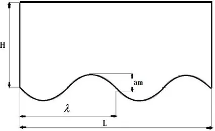
The basic geometry considered, consists of a channel with periodic sinusoidal wavy structures as lower wall and flat walls in the upper portion and is symmetric in nature, as shown in Figure 1. The working fluid was assumed to be water with constant fluid properties, and the flow was considered to be turbulent, incompressible, steady and two-dimensional.
FIGURE 1. COMPUTATIONAL DOMAIN WITH 0.1H AMPLITUDE
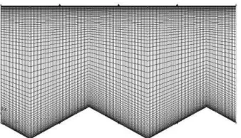
The values of H and L, the height and length of the pipe are 20mm and 40mm respectively. am is the amplitude of wave like wall and the value is taken as 0 to 0.1H mm and the wave length, λ of the wave is 20 mm. The grid used for the computations are generated using Gambit 2.3.6, and the mesh is exported to OpenFOAM. A cartesian grid as shown in Figure 3 is used, with first grid point near the wall located at y ≤1 and then stretched out in the wall normal direction. Finer grid spacing close to the duct walls and ensured to resolve the near-wall flow. No-slip conditions are used at the walls with zero gradient of pressure. The wall spacing of the first grid is found out to be 2.2097 × 10⁻³ by the equation given below:
Copyright to IJIRSET www.ijirset.com 804
element size has been studied for Re = 6760. In order to get a two dimensional mesh only one grid cell is considered in the z direction. The calculations were carried out with 200(x) × 100(y) grid points which was obtained after a grid independence test and the details are shown in fig. 2. The free stream velocity (U0) ahead of the step is 1.079 m/s and no-slip boundary conditions are used at the walls.
FIGURE 2. GRID INDEPENDENCE TEST TO GET THE OPTIMUM GRID FOR SIMULATIONS
FIGURE 3. COMPUTATIONAL GRID WITH WAVY WALL SURFACE OF 0.1H AMPLITUDE
Two additional cases of wall roughness were also simulated, with walls having triangular and rectangular ribs. Meshes were generated similarly for different amplitudes of the ribs ranging from 0 to 0.1H. But care was taken, so that the cross sectional area of each triangular wall and rectangular ribbed wall cases, has the same cross sectional area with their wavy wall counterpart. So calculations were done and geometric or dimensional aspects were altered to attain the above condition.
Copyright to IJIRSET www.ijirset.com 805
FIGURE 4 (b). COMPUTATIONAL GRID WITH RECTANGULAR RIBBED WALL SURFACE OF 0.1H AMPLITUDE
3. Validation of turbulence model
A turbulent flow through flat plate was done in the preliminary stage, for the validation of turbulence model. A y+ value less than 1 was generated for the flat plate turbulent flow.
For Re < 2 x 10⁶
Launder- Sharma model is opted after comparing the results with other models
4. Simulation of turbulent flow through wavy wall channel.
The simulation of turbulent flow in wavy wall channel is carried out using a standard steady-state solver for incompressible, turbulent flow called simpleFoam in OpenFOAM, which is then modified to obtain a temperature dependent version, named as simpleHeatFoam. Turbulent flow through wavy wall channel was done for 6 different meshes of amplitude ranging from 0 to 0.1H. The lower and upper walls of the wavy channel are constantly heated with a temperature of 275K and the fluid flowing through the channel is with a temperature of 350K.Simulations are performed for different amplitudes of wavy wall channel, ranging from 0 to 0.1H.
Because the temperature values are fixed for both the upper and lower wall, the heat of the fluid will dissipate through the walls because of convection. Ranging from 0 amplitude to 0.1H amplitude, when undergoing turbulent flow the wavy wall channel, different heat transfer characteristics are obtained. The analysis is extended to triangular and rectangular ribbed geometries.
5. Results and discussions
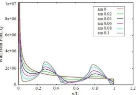
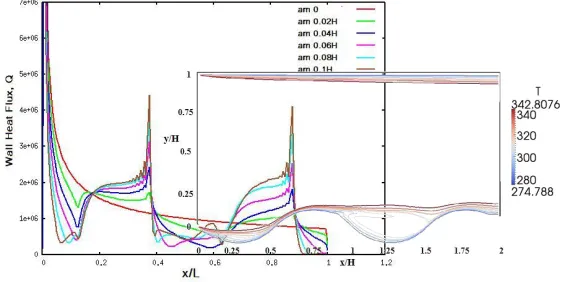
The wall heat flux values went on varying with the length of the pipe. These variations was also be depended on the amplitudes of the wavy wall and increased with increasing wavy amplitude–wavelength. The variation of wall heat flux, Q in six different cases are shown in the Figure 5 for amplitudes of 0, 0.02H, 0.04H, 0.06H, 0.08H and 0.1H respectively.
Copyright to IJIRSET www.ijirset.com 806
From the Figure 5, as the amplitude increases, at amplitude 0.02H recirculation occurs at the trough of the wave as result of the decreasing friction coefficient. So separation and re-attachment points are formed on the locations where the friction coefficient vanishes. The wall heat flux values are higher in the converging section of the channel (peak of the crust) than in the diverging section, because the converging section has a higher average velocity and velocity gradient, which increases the heat transfer rate. Conversely, the flow reversal has a low velocity gradient near the wall surface in each trough, which decreases the heat transfer rate.
To find the critical value of amplitude, the average Nusselt number values obtained for different amplitudes were compared and shown in Figure 7.
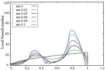
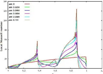
FIGURE 6. COMPARISON OF LOCAL NUSSELT NUMBER VALUES FOR SIX DIFFERENT CASES OF AMPLITUDES OF WAVY WALL
From the Figure 6, it can be seen that the Local Nusselt number values are maximum at the peak of the crust position of the each wave. The wall heat flux and local Nusselt number values decrease to zero at exit where x/L = 1, because only two patterns of wavy walls were taken for simulations. The Average Nusselt number values are then found out from the average values of Local Nusselt number values on the heated wall using the correlation of Gnielinski [6] for heat transfer in turbulent channel flow, which is given below,
To find the critical value of amplitude, the average Nusselt number values obtained for different amplitudes were compared and shown in Figure 7.
Copyright to IJIRSET www.ijirset.com 807
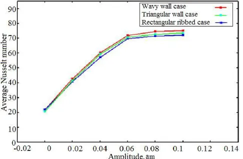
From figure 7, it is evident that the Average Nusselt number increases with increase in the amplitude of the wavy wall up to an amplitude of 0.06H, after which the Nusselt number approximately remains constant. So it was found that 0.06H is the critical amplitude where the maximum heat transfer occurs. So at critical amplitude value, the wavy wall channel is an effective heat transfer device, especially for higher Reynolds numbers.
Temperature isotherm contours at a given time, in the wavy wall case for amplitudes 0.06 t& 0.1H are given in figures 8 (a) & (b). Temperature contours, which are straight in the flat-plate channel, are distorted in the recirculation region when amplitudes are increasing.
(a) (b) FIGURE 8 (a), (b)
ISOTHERMS FOR WAVY WALL CHANNEL WITH AMPLITUDE 0.06H, 0.1H
5.1 Comparisons with triangular and rectangular ribbed wall cases.
Wall heat flux values for triangular and rectangular ribbed cases show the same trend of the wavy wall case. These cases also showed the presence of re-circulations, separation, re-attachment points etc. The wall heat flux comparison for the two cases is given below in Fig. 9 and 10. There is a steep increase in wall heat flux values than a gradual smooth change like in the case of wavy wall channel. Another notable difference when compared to the wavy wall cases is the presence of fluctuations even in smaller dimensions of the ribs.
Copyright to IJIRSET www.ijirset.com 808
FIGURE 10. WALL HEAT FLUX VALUES FOR DIFFERENT CASES OF RECTANGULAR RIBBED WALL
The wall heat flux values for triangular wall case, there is zig-zag variations and slight fluctuations when reaching to the top crust position, where the wall heat values are maximum like in the case of wavy wall. In triangular wall sudden flow reversals and variations of flow conditions are present.
FIGURE 11. LOCAL NUSSELT NUMBER VALUES FOR DIFFERENT CASES OF TRIANGULAR WALL
FIGURE 12. LOCAL NUSSELT NUMBER VALUES FOR DIFFERENT CASES RECTANGULAR RIBBED WALL
Copyright to IJIRSET www.ijirset.com 809
with the amplitude-wave length ratio. Local Nusselt number comparison for triangular and rectangular ribbed cases also show the same trend of increasing Nusselt number values. In these cases also the critical value for amplitude-wavelength ratio is 0.06H, after which, no significant improvement in heat transfer capabilities is observed. All the three wall cases are compared on the basis of the Average Nusselt number values and the comparison of these three wall cases is shown in fig 13. It is found that wavy walls have comparatively large values of average Nusselt number at critical amplitude.
FIGURE 13. AVERAGE NUSSELT NUMBER VALUES FOR SIX DIFFERENT CASES OF WAVY, TRIANGULAR & RECTANGULAR RIBBED WALL CASES
6. Conclusions
In this study numerical analysis of turbulent flow and heat transfer are performed in channels with complex configurations like wavy, triangular and rectangular ribbed walls. The turbulence model was validated with the turbulent flow over flat plate and the solver was benchmarked with Blasius Similarity solution. The predicted results are in good agreement with analytical solutions. The critical amplitude, where the maximum heat transfer through the wall will occur, was found out with a geometric parametric study for all the three cases of ribbed walls. The comparison of results of the wavy wall with triangular and rectangular ribbed walls shows that wavy walls are better heat transfer enhancement devices.
REFERENCES
[1] A. Z. Dellil, A. Azzi, and B. A. Jubran,2004 “Turbulent flow and convective heat transfer in a wavy wall channel”. Int. Journal of Heat and
Mass Transfer, 40(1):pp.793–799
[2] Fernando V. Castellões, João N.N. Quaresma, and Renato M. Cotta.2010”Convective heat transfer enhancement in low Reynolds number”
Int. Journal of Heat and Mass Transfer. 53(1)pp.2022–2034
[3] Nils Kruse, and Philipp Rudolf von
Rohr,2006,”Structure of turbulent heat flux in a flow over a heated wavy wall.”Int. Journal of Heat and Mass Transfer. 49(1):pp.3514-3529
[4] K.A. Hafez , O.A. Elsamni, and K.Y. Zakaria “Numerical investigation of the fully developed turbulent flow over a moving wavy wall
using k-e turbulence model”.Alexandria Engineering Journal. 50(1):165-176, 2011.
[5] ShyyWoei Chang, Arthur William Lees, and TsuChien Chou. “Heat transfer and pressure drop in furrowed channels with transverse and
skewed sinusoidal wavy walls”. Int. Journal of Heat and Mass Transfer. 52(1):4592-4603, 2009
[6] Gnielinski V.,1976”New equations for heat and mass transfer in turbulent pipe and channel flow.” Int. Journal for Chemical