International Journal of Innovative Research in Science, Engineering and Technology
An ISO 3297: 2007 Certified Organization Volume 6, Special Issue 4, March 2017
National Conference on Technological Advancements in Civil and Mechanical Engineering – (NCTACME'17)
17th -18th March 2017
Organized by
C. H. Mohammed Koya
KMEA Engineering College, Kerala- 683561, India
A Study on Mini Jet Engine
Edwin Cyril1, B Shobin Mathew2, Akhil Mathew3, Gino Sunny4
B. Tech Student, Department of Mechanical Engineering, VJCET College, Ernakulam, India1,2,3,4
ABSTRACT: The use of Mini Jet Enginesin the present scenario is very limited. They provide many advantages over conventional reciprocating engines such as high power to weight ratio, cleaner combustion , less number of moving parts etc. These advantages along with their Smaller Size and Lower Weight they present themselves as the ideal alternative to reciprocating engines in hybrid vehicles. The features of the engine are studied in detail and brought forth in this project wherein a mini jet engine is designed, fabricated, assembled and run at operating speeds.
KEYWORDS: Jet engine, ECU, ATF, Dynamic balancing
.
I. INTRODUCTION
The present society being more environmentally conscious, companies are developing novel methods to achieve a balance in power output, fuel economy and at the same time ensure cleaner emissions. The use of mini jet engines which gives cleaner combustion, having less number of moving parts and having lower body weight thereby of greater payload capacity is visualized to replace conventional engines in the near future in the application of hybrid cars. These engines would power the batteries of such hybrid vehicles enabling them to cover larger distances without recharging using an external source of electric power. Taking in the magnitude of the role these mini engines would soon play in our lives this journal focuses on the fabrication, assembly, testing and study of the jet engine on a basic level. This project also aims to depict the feasibility of manufacture of such engines in our country
Parts of the Engine.
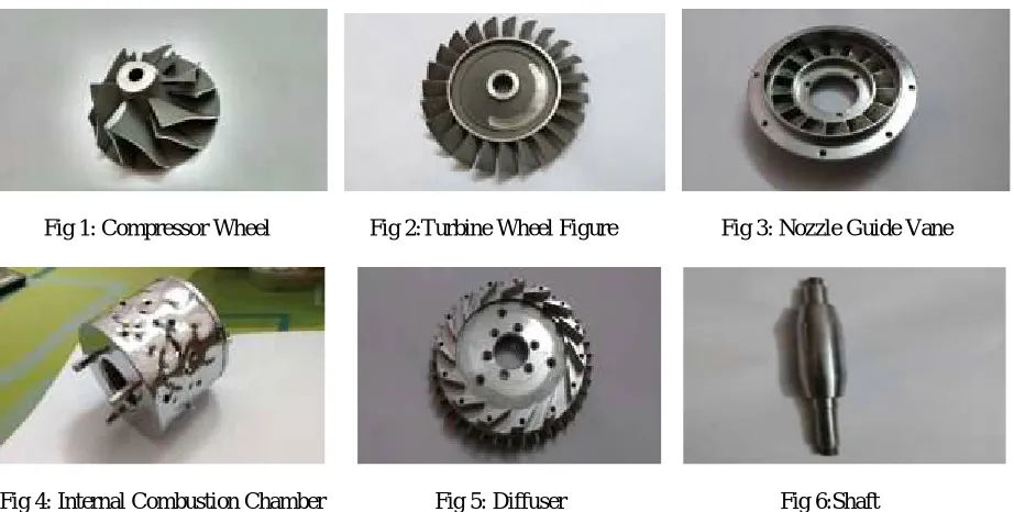
The major components of the engine are a) Shaft b)Turbine c)Compressor d)Diffuser e)Nozzle guide vane f)Shaft tunnel g)Annular combustion chamber h)Exhaust nozzle i)Bearings j)Burner. Shaft-The turbine and compressor are attached to the shaft and form the rotary components of the engine. Turbine converts the energy in the burnt gases to rotary motion. Compressor-Sucks and compresses the air to the required pressure needed for combustion. Diffuser-Further increases the pressure of the flowing air to the combustion chamber
.
Nozzle guide vanes-Guides the heated gases towards the turbine blades. Shaft tunnel-The shaft rotates within this component. Annular combustion chamber- The combustion of gases takes place here. The air enters through the passages (holes) provided on the chamber in three zones. Exhaust nozzle-The burnt out fuel air mixture from the turbine flows out through this nozzle. This further increases the thrust output of the engine. Bearings-The shaft is supported on the bearings. Burner-The fuel is introduced into the combustion chamber by these burners. There are six reverse flow burners meaning the fuel is introduced into the chamber against the flow of compressed air. A few major dimensions are mentioned below:Shaft: Length-165mm; Max dia-14.5mm Turbine: Max dia-66mm
Compressor: Max dia-66mm Diffuser: 97mm
The other parts include
k)Housing l)Compressor cover m)Spring n)Nuts and bolts
Fig 1: Compressor Wheel Fig 2:Turbine Wheel Figure Fig 3: Nozzle Guide Vane
Fig 4: Internal Combustion Chamber Fig 5: Diffuser Fig 6:Shaft
The other auxiliary parts include
a)Starting motor- Provides a sustainable rpm of 25000rpm, this enables sufficient speed for initial functioning of the engine.
b)Fuel pump-Pumps fuel to the engine at the required rate set by the operator. c)Fuel lines-Transfers the fuel to the combustion chamber
d)ECU(Electronic control unit)-The values obtained from the sensors are processed and sent to the display by the ECU.
e)Rpm sensor-Sensor to detect the speed of the rotary components.
f)Temperature sensor-Sensor to measure the temperature within the engine.
g)Remote control-Enables wireless control
.
Fig7:Starter Motor Fig 8:Fuel Pump
Fuel Employed
The fuel used is ATF(Aviation Turbo Fuel. The lubricant used is a mixture of fuel with 5% Mobil jet oil. Initially the tubes and burners are preheated by burning butane or propane or a mixture of both through the pipes. This heats the lines such that by the time the fuel(ATF) reaches the combustion chamber it vaporizes and gets evenly mixed with the air. In order to accomplish this LPG(Liquefied Petroleum gas) is used.
II. FABRICATION
Hard to manufacture parts requiring high degree of accuracy were imported. They are a)Compressor b)Turbine c)Nozzle guide vane All the rest of the parts where manufactured indigenously. The machine used for this purpose was a 5 axis CNC machine HURCO VMX3OU.
Fig 11:5 Axis CNC Lathe
III.CONSTRUCTION
The assembly of the parts are as follows. The compressor and the turbine are connected to the shaft and rotates with it. The shaft is supported on bearings which fit neatly into the shaft tunnel. The tunnel is attached to the diffuser at the inlet and to the nozzle guide vane at the exit end. The diffuser is in turn attached to the housing by means of screws. The compressor cover protecting the compressor is attached to the housing. At the exit end the shaft tunnel is attached to the NGV which in turn is connected to the housing and the exhaust nozzle. Sufficient clearance is given between the rotary components(0.5mm- 1mm) to ensure smooth operation.
IV.PRINCIPLE OF OPERATION
The engine operates on the principle of Braytons cycle. The Brayton cycle is a thermodynamic cycle named after George Bailey Brayton that describes the workings of a constant pressure heat engine
Fig 13. Brayton cycle
The working of a jet as per Braytons cycle is shown above. The air is taken in from the atmosphere and compressed and then sent to the combustion chamber. Here fuel is mixed along with the air and ignited. The large amount of energy released is used to run the turbine and the work done by the turbine is used to run the compressor as well thus the cycle continues. In this cycle the heat addition is at a constant pressure. The P-V and T-S diagrams are also shown above.
V. DYNAMIC BALANCING
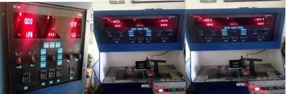
In order to ensure smooth rotation of the rotary components devoid of any vibrations balancing of the fabricated parts is mandatory. This is an important step as any unnecessary vibrations could possibly cause permanent damage to the system. The dynamic balancing was conducted on an ABRO DT100 model dynamic balancing machine. The results of the test conducted was
Table 1. Experimental Results
Degree RPM Left
plane(mg)
Right Plane(mg)
128 431 0.00 -0.19
103 1013 -0.03 -0.26
108 1017 -0.03 -0.27
The components were balanced by rectifying the positioning of the spacer rings, compressor wheel and that of the turbine wheel also taking into consideration at what degree the parts are to be assembled on the shaft.
Fig17:Balancing of rotor assembly
VI. WORKING
The machine is started using a motor of 25000 rpm coupled to the compressor nut. This is the minimum speed required to start a sustainable combustion. Once started the air is sucked in and compressed radially and sent through the diffuser. In the compressor the pressure is increased with slight increase in velocity, the diffuser allows for further increase in pressure and at the same time brings the velocity of flow to required limits needed for combustion. The air coming in from the diffuser flows into the passage beneath the cover before flowing into the annular combustion chamber via the air passages provided on it. The fuel is injected by six reverse flow fuel burners. The fuel is injected against the flow of air in the combustion chamber. The fuel used is LPG and ATF(Aviation Turbo Fuel). The LPG is used to preheat the burner, this enables better vaporization of ATF which is the main fuel. The air mixes with the fuel in the combustion chamber and is ignited by the ignition. The air is taken in at three regions of the combustion chamber. The heated air passes through the nozzle guide vanes and is directed onto the turbine vanes. This does work on the turbine and the turbine rotates, the work thus produced is given to the compressor. This power produced in the turbine can also be used for other purposes wherein comes the application of machine.
VII. TESTING
The test set up consisting of setting up a fuel level meter on the side of the fuel tank. The amount of fuel consumed for a certain constant time period is measured keeping both the rpm and temperature constant. This value is computed to obtain the mass of fuel consumed.
Mass = Volume × Density
(Density of fuel(ATF) =775-840 kg/m3 at 15 degree Celsius.(Average value = 807.5 kg/m3.
Calorific value of jet fuel is in the range of 8000-9480 J/Kg. The average value is again opted for measurement
Thus the theoretical heat evolved can be calculated as:
Q=(Mass of fuel consumed × calorific value)(J)
The value of rpm of rotor and temperature readings of the exhaust gases can also be obtained from the experimental set up. The engine is run at different rpm and temperature readings are taken.
VIII. CONCLUSION
The mini jet engine was assembled and placed on a suitable base. The engine was run at a suitable speed and readings were taken. It worked satisfactorily and provided a unique opportunity to witness the working of a jet engine at close range. This study enabled a deeper study and better understanding of the designs used in the construction of such engines.
REFERENCES
[1] .Aly M. Elzahaby et al.(2016): Theoretical and Experimental Analysis of a Micro Turbojet Engine’s Performance.
[2] .R. Davison et al.(2004Craig ): Set up and operational experience with a micro turbine engine for research and
[3] education.
[4] Junting Xiang et al.(2016): Study of KJ-66 micro gas turbine compressor: Steady and unsteady Reynolds-averaged
[5] Navier–Stokes approach