Coordination of Recloser and Fuse in a Distribution System
With the integration of Distributed Generation and
Superconducting Fault Current Limiter
A.Bharath Kumar & G.V.Marutheswar
1PG Student, Dept of EEE, S V University College Of Engineering, Tirupati . 2 Professor, Dept of EEE, S V University College Of Engineering, Tirupati.
1[email protected],[email protected]
Abstract: Distributed Generation (DG) has increased largely from the past two decades due to its advantages. In the distribution network, the superconducting fault current limiters(SFCL) are placed to reduce the amount of fault current by the effect of impedance. In this paper, we studied the fuse recloser coordination when DGs and SFCL are placed into the distribution system. Normally fuses are placed near the distribution side and the reclosers are placed near the substation. Whenever apermanent fault occurs in the distribution network, the fuse is set to operate before the delayed operation of the recloser to overcomemiscoordination problem. By the integration of DG, the fault current seen by the recloser is less than the fault current seen by the fuse thereby causing the miscoordination. By placing the SFCL into the distribution system, the fuse may not melt during the delay operation of the recloser because of insufficient heat due to the decrease in the fault currents. This paper presents a control strategy with which the coordination is maintained and the load is shared according to the ratings of DGs.
Keywords—Distributed Generation(DG), Superconducting fault current limiter(SFCL), Fuse Recloser coordination.
I. INTRODUCTION
DistributedGeneration(DG) offersvarious advantagesfor users. DG accounts to satisfythe increasedload demand without the expansion of transmissionsystem. As DG is connected at the distributionnetwork, the transmission losses are reduced. [2]
DG utilizes non-conventional energy resources which are unpredictable and hence to integrate DG into the distribution system, converter is necessary. The integration of DG into the distribution system leads to some problems in the power quality and power system protection. Generally the distribution networks are radial feeders, with the integration of DG, the fundamental radial feeder structure is changed to mesh feeder structure.[1] This can negatively impact the protection of the distribution system. The major issues which arise by the integration of DG into the
distribution system are
fuse-reclosermiscoordination, unintentional
islanding, sympathetic tripping and reduction of reach of the protecting element.
DG capacity doesn’t meet the required load demand. Modifying the protection system is not economical and is more complicated.[2] Using SFCL in the power distribution network, the fault currents in the system reduced and hence the fuse doesn’t melt due to insufficient heat. In this case the fuse is to be reselected for proper coordination of fuse and recloser. However the reselection of fuse is complicated by considering the impedances of alternator, distribution network and fault.[4]
Operating principle of SFCL:
The operating principle of a hybrid SFCL is as follows. During normal condition, the currents flow through the superconductor which is used to sense the fault currents. Whenever a fault occurs, the superconductor is quenched and generates high impedance. Hence the fault currents flow through the parallel paths. The current flowing through the driving coil generates an electromagnetic force and operates the fast switch which opens S/W and closes the short contactor as shown in the figure below. Now the fault currents flow through the parallel paths in the current limiting part and the fault current is limited by the current limiting reactor.
Fig.1. Configuration of Hybrid SFCL
In this paper, a control strategy is proposed which controls the output current of DG according to the changes in the terminal voltage of DG. In addition, the proposed method is inexpensive as the original protection system need not to be changed.
II. FUSE RECLOSER
MISCOORDINATION
Coordination between different protecting equipment in the distribution system should be maintained properly for effective working of the power system. Recloser is a circuit breaker that can automatically close the breaker after it has opened due to fault. If the fault current in the recloser is larger than the threshold value, the recloser instantaneously tripped based on the time current characteristics. After several fast trip operations of recloser, the recloser starts delayed operation. If the fault is not removed after several fast trip and delayed operations, the recloser would assess the fault to be permanent and trips permanently. Fuse is a basic overcurrent protective device which interrupts the fault current. When large current flows through fuse, it will melt depending on heat energy generated by 𝐼2Rt and interrupt the fault current after melting time.
In distribution system, fuse is placed at the load side and the recloser is placed at the substation side. In the fuse saving scheme, when a fault occurs, first the recloser should operate based on its fast time current curve. Around 70% of the faults which occur in the distribution network are temporary faults, they will be quenched during fast reclosing actions. If the fault is permanent, the fuse is set to operate between fast and time delayed operations of the recloser.
should operate in between the fast and delayed operation of the recloser for proper coordination.
Due to the integration of DGs into the distribution network, the fault current seen by the recloser is less than the fault current seen by the fuse thereby fuse operates first and trips the system. Thus the fuse recloser coordination is failed. The additional fault current which is seen by the fuse is because of the currents injected by the DGs during the fault condition.
Fi g. 2. Fuse Reclo ser Coord inatio n
III. CURRENT CONTROL SCHEME
To reduce the adverse effects of DGs on the fuse recloser coordination, an effectiveDG current control scheme is proposed in this section. The ideal way to reduce the impact of DGs on the distribution protection system is to sense the fault and trip all the converters in that protected zone. But these converters are incapable in differentiating the faults and short term disturbances. Thus in all the abnormal conditions, converter tripping may lead to unnecessary power outages. The only way to get rid of the short term disturbances and to avoid unnecessary tripping is to introduce time delay according to IEEE std. 1547.
Voltage at PCC Maximum tripping
time(sec)
V<50% 0.16
50%<V<88% 2
88%<V<110% Normal Operation
110%<V<120% 1
V>137% 0.16
Table.1. IEEE std 1547
To mitigate the miscoordination problem, the converter current should be controlled according to the severity of the fault instead of blocking the converter. Through the literature survey, it is clear that the miscoordination doesn’t depend on the fault location[5], the converters which are near the fault will produce more impact on the protection and should decrease their contribution to the fault current. Similarly the DGs which are far from the fault point will have no effect on the protection system and can continue to supply power to the utilities.
To implement the current control strategy, the reference currents to the DGs can be determined by equations 1 and 2.
𝑰𝑟𝑒𝑓 =𝑃𝑑𝑒𝑠𝑖𝑟𝑒𝑑
𝑉𝑃𝐶𝐶 , 𝑉𝑃𝐶𝐶 ≥ 0.88 p.u (1)
𝐼𝑟𝑒𝑓 = 𝑘𝑉𝑃𝐶𝐶𝑛 𝐼
𝑚𝑎𝑥,𝑉𝑃𝐶𝐶< 0.88p.u (2) (2)
Where 𝐼𝑟𝑒𝑓 is the reference current to the converter, 𝐼𝑚𝑎𝑥 is the maximum current at
𝑉𝑃𝐶𝐶 =0.88 p.u , 𝑉𝑃𝐶𝐶 is the rms voltage at the
point of common coupling of DGs to the distribution system, 𝑃𝑑𝑒𝑠𝑖𝑟𝑒𝑑 is the output power
Generally the constant n is the sensitivity factor of the control scheme and it is taken as 3. High value of n may lead the control scheme to be more sensitive for even small voltage changes. After chosing the value of n
the constant k can be determined by the equation 3.
𝑘 = 1
0.88∗𝑉𝑃𝐶𝐶 𝑛 +1 (3)
The flowchart which illustrates the above inverter current control strategy is is given by the figure 3.
Fig.3. Flowchart of control strategy
IV. SIMULATION RESULTS
A. Mitigation of Fuse
RecloserMiscoordination
To verify the proposed control strategy for proper coordination of fuse and recloser, the
above simple system is considered. For proper fuse recloser coordination, when a fault occurs the recloser should act first.
Fig.4. Simulink model of the system
Fig.5. Simulink model of the system with SFCL
Fig.6. Signal to the Recloser
Fig.7. Signal to the Fuse
Currents through recloser and fuse are given by the following figures 8 and 9.
Fig.8. Current through Recloser
By the addition of SFCL into the distribution system, the fault current is reduced by the operation of SFCL and the coordination
is not affected by the proper selection of fuse. The reduced fault currents in the system are shown in the following figures 10 and 11.
Fig.9. Current through Fuse
Fig.10. Current through Recloser (with SFCL)
Fig.11. Current through fuse (with SFCL)
because that the DGs stop generating the power.
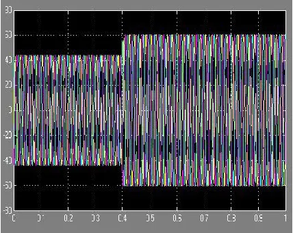
B. Power sharing between the DGs
In the considered system, an additional load has been added at 0.4sec and the changes in the flow of currents through DGs are studied. Here the DGs are of equal rating and hence the load is equally shared by the two DGs. The currents through DGs are shown in the following figures 12 and 13.
Fig.12. Current supplied by DG1
Fig.13. Current supplied by DG2
Table 2. Summary of simulation results
V. CONCLUSION
Distributed Generation is the most effective way to satisfy the increasing load demands whereas an SFCL is used for the reduction of fault current in the system. With the addition of these two components into the power distribution system, fuse recloser coordination is failed because the DGs continue to supply during the fault and fuse doesn’t melt due to insufficient heat energy by the reduced fault currents. Impact of SFCL can be eliminated by proper selection of fuse rating. To mitigate the impacts of DG, a simple and effective current control scheme was proposed such that the converter current adjusts according to the severity of the fault. The proposed strategy is economical as it doesn’t require modifying the existing protecting equipment and it is robust
against short-term disturbances. The
REFERENCES
[1] RaminiHareesh and Pramod C P, “ Distributed Generation integration with enhanced power system protection,” 2015 IEEE International Conference on Technological Advancements in Power & Energy.
[2] HesamYazdanpanahi, YunWei Li, “A New control strategy to mitigate the impact of inverter based DGs on protection system,” IEEE Transactions on smart grid, Vol.3, no.3,Sep2012
[3] S.Chaitusaney and A.Yokoyama, “ An appropriate distributed generation sizing considering recloser fuse coordination,” in Proc.IEEETransm. Distrib. Conf. Eshib.: Asia Pacific, 2005,pp. 1-6
[4] M.H. Kim, S.H. Lim, J.F. Moon and J.C. Kim,’ Method of recloser fuse coordination in a power distribution system with superconducting fault current limiter,” IEEE Transactions on
Applied superconductivity, Vol.20,
No.3,June2010
[5] AdlyGirgis, Sukumar Brahma,” Effect of Distributed Generation on protective device coordination in distribution system”
[6] R. A. Walling, R.Saint, R.C. Dugan, J.Burke and L.A. Kojovic,” Summary of distributed resources impact on power delivery system,” IEEE Trans. Power Del., Vol.23,No.3, pp.1636-1644,Jul.2008
[7] B.W.Lee, K.B.Park and I.S.Oh,” Practical application issues of superconducting fault current limiters for electric power system,”
IEEE Trans. Appl. Supercond., vol.18, no.2, pp.620-623, Jun.2008