Ferrofluid Actuation Based Frequency Reconfigurable Patch Antenna
Rocktotpal Baruah and Nidhi S. Bhattacharyya*
Abstract—This work describes the fabrication and characterization of a frequency reconfigurable patch antenna using ferrofluid actuation. The reconfiguration is based on a variation of the dielectric constant of the substrate. For this, the substrate is modified by placing channels in it filled with ferrofluid and isopropanol-water solution. The relative position of ferrofluid along the channels is controlled by an external magnetic field which results in a relocatable spatial difference in the dielectric constant value. The targeted reconfigurability with stable radiation characteristics at the accessible frequencies is validated through antenna reflection loss and radiation pattern measurements. Additionally, actuation speed of the fluid immerged in the polar mixture is measured by sequential image analysis.
1. INTRODUCTION
Reconfigurable antennas are a special category of antennas whose operational features can be modified according to requirements. Such capability would be of significant values for tuning the resonant frequency, changing the direction and shape of radiation pattern and polarization. The functional behaviours of reconfigurable antennas are mostly readjusted by changing the configuration of radiating elements, typically, by using electrical or micromechanical switches [1, 2]. Though these switches have an inherent advantage of fast switching speed and can be used over a wide frequency range; issues like nonlinearity and possible interference due to the presence of biasing lines are encountered [3]. In the past few years, apart from these switches, there has been growing interest in using fluidic channels to reconfigure antenna characteristics [4–7]. Most of these approaches use liquid metal as antenna radiators or parasitically coupled elements; which is pumped in and out using external control mechanisms [8–14]. Here, we present an antenna architecture that can tune its resonating frequency by changing the dielectric behaviour of the substrate material underneath the radiating patch. The challenge with this concept of tuning is to significantly alter the material’s dielectric constant so that a substantial amount of shifting in antenna’s resonating frequency is achieved. We address this challenge by embedding microfluidic channels into the substrate. An immiscible mixture of polar liquid of relatively high dielectric constant and a colloidal dispersion of small single domain magnetic particles suspended in a carrier fluid (ferrofluid) with a lower dielectric constant is injected into the micro channels. As both the solution has a distinct value of permittivity, a spatial variation is possible along the channel length by changing the relative positions of the two fluids within the channel and thus, effective permittivity of the substrate can be altered. High responsiveness of the ferrofluid (FF) to external magnetic fields allows selective positioning and necessary lateral displacements of the mixture. In this investigation, a mixture of isopropanol–deionised water (ISPW) solution is used as a high permittivity polar fluid. In addition to the mentioned dielectric constant variation, the solution also provides a slip layer between the FF and the channel wall which helps in reducing the wettability of the magnetic suspension. A pair of electromagnets (EM) is used to drive the ferrofluid through the trenches. The proof of concept antenna is designed to exhibits frequency reconfigurability with stable radiation patterns. The work
Received 25 July 2018, Accepted 4 October 2018, Scheduled 17 October 2018 * Corresponding author: Nidhi S. Bhattacharyya ([email protected]).
2. DESIGN APPROACH
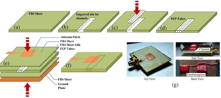
The antenna is a rectangular microstrip patch fabricated on an engineered FR4 substrate with fluorinated ethylene propylene (FEP) fluidic channels. The engineered substrate is a sandwich structure composed of one un-cladded FR4 slab ofεr = 4.3 and thickness 1.4 mm inclosing the tubing in it and is covered on the top and bottom by two additional comparatively thin FR4 layers. The middle sheet is engraved to house the FEP channels of the diameter approximating to 0.9 mm with a wall thickness of
∼0.5 mm and two very thin (0.2 mm) single side copper cladded FR4 layers are glued to this modified section. The antenna is etched on one of these copper cladded sides while the other side acts as the ground plane. The designed antenna is edge feed using a 50 Ω microstrip line with a quarter wave transformer. The design scheme of the antenna is presented in Figure 1. Antenna patch dimensions are calculated to resonate at 8.75 GHz, for 1.8 mm thick FR4 substrate as shown in Figure 2. Care is taken while placing the tubes in the substrate, as their position under the antenna patch is important in this approach. It is well known that in case of rectangular microstrip patch antenna (RMA) fringing field line concentrations are maximum at the patch edges and hence, maximum penetration into the substrate occurs across the edges [15, 16]. The FEP tubes are placed just beneath the radiating edge opposite to the feeding edge. To maximize the effect of spatially varying dielectric constant on the resonant frequency, the tubes are positioned such that it covers the extended patch length, ΔL, occurred due to fringing [15]. For this, channels are placed over an area of width equal to twice of ΔL to ensure maximum penetration of the fringing fields. As the channels are to contain two fluids of identical volume and each of these fluids needs to cover the entire length of the radiating edge of the antenna patch. The length of the channels is kept slightly larger than twice the patch width,W (here, it is about 24.88 mm). These extra millimetres are used to minimize the effect of the fluid held at position B on the resonant frequency. The parameters are calculated using the standards design equations of a RMA.
The tubes are first filled with a 3 : 1 mixture of isopropanol and deionized water (ISPW) and then a part of the solution is replaced by ferrofluid. While filling the tubes, it is confirmed that no air bubble is formed in the channels. The volume occupied by each of the liquids are equal and covers a tube length of
∼12.44 mm. Tubes are sealed properly once they are completely filled. Ferrofluid used in this approach is prepared by dispersing chemically synthesized Fe3O4 nanoparticles (∼6 nm) in a hydrocarbon based carrier fluid (Hexane) [17, 18]. Two electromagnets having a maximum strength of 400 Gauss are used to control the position of FF in the channel.
3. RESULTS AND DISCUSSION
Measurements are carried out using an Agilent VNA (PNA E 8362C) and Antenna Measurement System from Diamond Engineering, U.S.A. To demonstrate the reversible frequency shifting, responses of the antenna at the sequential states are recorded by changing the ferrofluid’s position as shown in Figure 2(d). Simulation studies are carried out using CST MW Studio to confirm the measured results. In the simulation process, a computer aided design (CAD) of the proposed antenna is analysed. The embedded fluids are simulated based on the data obtained from the material measurement studies. For Mode 1 simulations are run positioning ISPW under the antenna patch and FF in the remaining part of the channels and similarly reverse is done for Mode 2. An unmodified RMA and a modified antenna with no fluids within the channels are simulated to mimic the other two conditions. Figure 3 shows the simulated antenna structure and cross sectional views of the modified antenna substrate for the Mode 1 and Mode 2.
(a) (b) (c) (d)
(e) (f)
(g)
Figure 1. Fabrication scheme of the proposed antenna: (a) Unmodified FR4 sheet; (b) Engraved slot; (c) Insertion of channels; (d) FR4 sheet housing micro channels; (e) Stacking of various layers; (f) Final prototype with marked channel position (dotted lines); (g) Fabricated antenna with three different viewing angle.
(a) (b) (c) (d)
Figure 2. A depiction of the method that reconfigures the antenna resonant frequency: (a) Top view of the antenna with patch and channel dimension marked; (b) Enlarged view showing the position of channels under the patch; (c) Back view (ground plane) of the antenna showing the position of the electromagnets with patch position in dotted lines; (d) Status of Electromagnets and corresponding positioning of liquids (grey colour indicating FF and white colour ISPW).
activating electromagnet EM1 and the mixture is at B, which results in a resonant frequency of 9.00 GHz with 6.80% of−10 dB bandwidth. The resonant frequency of Mode 1 i.e., 8.4 GHz can be retrieved by again activating EM2, which forces the ferrofluid to again come into the position B. Similarly, Mode 2 also can be achieved by simply activating EM1.
From the return loss study, it is observed that for both the filled conditions frequency of the antenna shifts towards the lower side of the spectrum as compared to that of empty (air filled) channel. Reason for this trend can be understood by considering the dielectric constant of the liquids in the microwave region and the basic equation of an RMA [15]. As illustrated in Figure 2(d), the effective dielectric constant of the modified substrate under the antenna patch is resulted because of the combined effect of the materials presents in that particular area. The effective dielectric constant experienced by the patch is controlled by altering the position of the fluids within the channels. With the altered fluid’s position, the constitution of the substrate under the patch changes and this leads to the variations in the dielectric constant value.
Mode Status Frequency (GHz) % Bandwidth Gain (dBi) EM 1 EM 2 Measured Simulated Measured Simulated
1 OFF ON 8.40 8.33 6.72 7.61 3.20
2 ON OFF 9.00 9.10 6.80 7.23 5.80
Antenna without channels
NA NA 8.65 8.75 5.43 5.70 5.96
Air filled
channels NA NA 9.46 9.48 5.50 6.75 6.21
tangent values for the range 8.4 GHz–12.4 GHz (measured using Agilent material measurement software 85071 and Agilent VNA). For FF dielectric constant is around 2.02 and 10.02 for ISPW mixture. With these fluids placed beneath the antenna radiator, the effective dielectric constant of the antenna substrate changes accordingly. For ISPW the value will be the highest and hence the lowest value of frequency (8.40 GHz). In case of FF, it is in second lowest position with a frequency at 9.00 GHz. Air filled channels offer the lowest value as air has a dielectric constant of nearly equal to 1 and results in a resonance at 9.46 GHz. Unmodified FR4 positioned second with a dielectric constant 4.3 and has a resonating notch at 8.65 GHz.
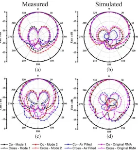
Radiation characteristics of the proposed antenna are also studied. Figure 6 shows measured and simulated radiation patterns of the antenna for both the reconfigured states, the original and air filled RMA. InXZ plane all the co-polarized patterns show a main lobe direction at 0◦ and 3 dB beam width of 96◦. In Y Z plane similar consistencies are observed with the main lobe direction at 5◦ and 3 dB beam width of 90◦. The antenna offers low cross polarization levels at all the frequencies. In Table 1 gain of the antenna for both the operating modes (Mode 1 and 2) along with the two other conditions are presented. The reduced gains of the antenna for the filled conditions compared to that of the empty one are primarily due to the lossy nature of the fluids used. When the FF with a loss tangent of 0.04 placed below the patch a gain of 5.80 dBi is recorded at 9.00 GHz and with the water propanol mixture having a dielectric loss tangent of 0.5, gain reduced to 3.20 dBi (8.40 GHz). A slightly increased gain of 5.96 dBi is observed for the FR4 substrate (loss tangent of ∼0.03) without the channels. In the air filled case, because of the low loss tangent value, the substrate offers a higher gain of 6.21 dBi.
(a) (b) (c)
Figure 4. Four distinct frequency responses illustrating the frequency reconfigurability of the antenna between two modes and responses of a standard RMA and antenna with empty (air filled) channels. Solid symbol represents measured data and half-filled symbol represents simulated data.
Figure 5. Real part of permittivity and loss tangent plot of FF and ISPW mixture.
(a) (b)
(c) (d)
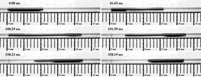
Figure 7. Sequential image analysis of the fluid transmission process. During the actuation a portion of FF (black fluid) covers a distance of∼12.00 mm in 108.29 milliseconds and completely shifts to the new position in 358.19 milliseconds.
The intent of this work is to demonstrate the possibility of frequency reconfiguration through liquid actuation. It is necessary to perform the actuation speed test for the liquids because frequency switching speed directly depends on the speed. Speed test is performed using a linear channel, a video camera with a capture rate of 120 fps and an electromagnet. The result reveals an actuation speed up to 110.82 mm/s and total transmission time of 358.19 milliseconds for a shifting distance of∼12.00 mm when sequential frames are analysed in the ImageJ software (Figure 7).
4. CONCLUSIONS
The paper presents a method to reconfigure resonant frequency through a magnetically aided actuation of fluids in a set of micro channels. In its current form, the antenna offers alternation of frequency between two values by laterally shifting the dielectric liquids. The two distinct resonances also have significant gain and beam width comparable to that of a standard RMA. The approach demonstrates a simple and effective technique to convert an RMA into a frequency reconfigurable antenna without disturbing the profile of the radiating patch. In this design absence of biasing lines, required for electronic switches, has a positive effect on the antenna radiation pattern and makes them stable at both the frequencies and resembles that of an RMA. Additionally, the demonstrated antenna has the potential to be developed as a frequency reconfigurable antenna with continuous tunability, if the electromagnets are replaced by a magnet fitted with a sliding mechanism along the channel length.
REFERENCES
1. Costantine, J., Y. Tawk, S. E. Barbin, and C. G. Christodoulou, “Reconfigurable antennas: Design and applications,” Proceedings of the IEEE, Vol. 103, 424–437, 2015.
2. Christodoulou, C. G., Y. Tawk, S. A. Lane, and S. R. Erwin, “Reconfigurable antennas for wireless and space applications,” Proceedings of the IEEE, Vol. 100, 2250–2261, 2012.
3. Yang, S., C. Zhang, H. K. Pan, A. E. Fathy, and V. K. Nair, “Frequency-reconfigurable antennas for multiradio wireless platforms,” IEEE Microwave Magazine, Vol. 10, 66–83, 2009.
4. Bhattacharjee, T., H. Jiang, and N. Behdad, “A fluidically tunable, dual-band patch antenna with closely spaced bands of operation,” IEEE Antennas and Wireless Propagation Letters, Vol. 15, 118–121, 2016.
5. Murray, C. and R. R. Franklin, “Independently tunable annular slot antenna resonant frequencies using fluids,”IEEE Antennas and Wireless Propagation Letters, Vol. 13, 1449–1452, 2014.
7. Dey, A. and G. Mumcu, “Microfluidically controlled frequency-tunable monopole antenna for high-power applications,”IEEE Antennas and Wireless Propagation Letters, Vol. 15, 226–229, 2016. 8. Kim, D., R. G. Pierce, R. Henderson, S. J. Doo, K. Yoo, and J.-B. Lee, “Liquid metal
actuation-based reversible frequency tunable monopole antenna,” Applied Physics Letters, Vol. 105, 234104, 2014.
9. Wang, M., C. Trlica, M. R. Khan, M. D. Dickey, and J. J. Adams, “A reconfigurable liquid metal antenna driven by electrochemically controlled capillarity,” Journal of Applied Physics, Vol. 117, 194901, 2015.
10. Morales, D., Morales, N. A. Stoute, Z. Yu, D. E. Aspnes, and M. D. Dickey, “Liquid gallium and the eutectic gallium indium (EGaIn) alloy: Dielectric functions from 1.24 to 3.1 eV by electrochemical reduction of surface oxides,”Applied Physics Letters, Vol. 109, 091905, 2016.
11. Khan, M. R., G. J. Hayes, J.-H. So, G. Lazzi, and M. D. Dickey, “A frequency shifting liquid metal antenna with pressure responsiveness,”Applied Physics Letters, Vol. 99, 013501, 2011.
12. King, A. J., J. F. Patrick, N. R. Sottos, S. R. White, G. H. Huff, and J. T. Bernhard, “Microfluidically switched frequency-reconfigurable slot antennas,” IEEE Antennas and Wireless Propagation Letters, Vol. 12, 828–831, 2013.
13. Morishita, A. M., C. K. Y. Kitamura, A. T. Ohta, and W. A. Shiroma, “A liquid-metal monopole array with tunable frequency, gain, and beam steering,”IEEE Antennas and Wireless Propagation Letters, Vol. 12, 1388–1391, 2013.
14. Rodrigo, D., L. Jofre, and B. A. Cetiner, “Circular beam-steering reconfigurable antenna with liquid metal parasitics,” IEEE Transactions on Antennas and Propagation, Vol. 60, 1796–1802, 2012.
15. Balanis, C. A., Antenna Theory: Analysis and Design, 3rd edition (With CD), Wiley India Pvt. Limited, 2009.
16. Garg, R.,Microstrip Antenna Design Handbook, Artech House, 2001.
17. Devi, M. and D. Mohanta, “Rheological properties of iron oxide based ferrofluids,”AIP Conference Proceedings, Vol. 1147, 495–501, 2009.