Scholarship@Western
Scholarship@Western
Electronic Thesis and Dissertation Repository
11-3-2017 4:30 PM
Functional Design and Analysis of a Linked Shoulder Prosthesis
Functional Design and Analysis of a Linked Shoulder Prosthesis
Emily West
The University of Western Ontario
Supervisor Dr. Louis Ferreira
The University of Western Ontario Co-Supervisor Dr. George Athwal
The University of Western Ontario
Graduate Program in Biomedical Engineering
A thesis submitted in partial fulfillment of the requirements for the degree in Master of Engineering Science
© Emily West 2017
Follow this and additional works at: https://ir.lib.uwo.ca/etd
Part of the Biomedical Devices and Instrumentation Commons
Recommended Citation Recommended Citation
West, Emily, "Functional Design and Analysis of a Linked Shoulder Prosthesis" (2017). Electronic Thesis and Dissertation Repository. 5149.
https://ir.lib.uwo.ca/etd/5149
This Dissertation/Thesis is brought to you for free and open access by Scholarship@Western. It has been accepted for inclusion in Electronic Thesis and Dissertation Repository by an authorized administrator of
i
Persistent shoulder instability following joint arthroplasty remains a concern with mixed
outcomes following clinical and surgical intervention. Thus, a linked universal joint implant
was developed and functionally analyzed. A virtual model of the linked implant was developed
and implanted in a 3D bony specimen to measure the available circumduction range of motion.
Stresses in the implant were estimated using finite element analysis based on joint loads during
activities of daily life. The glenoid fixation stress was evaluated using finite element analysis.
The results of this feasibility study show the linked implant is predicted to restore normal range
of motion, and withstand expected joint loads without yield or fatigue failure. Bone fixation
stress remains a concern, depending on the implant configuration and aggressive joint loading.
Keywords
Shoulder arthroplasty, Chronic Shoulder Instability, Salvage Procedure, Universal Joint,
ii
Co-Authorship Statement
Chapter 1: Emily West – sole author
Chapter 2: Emily West – study design, data collection, statistical analysis,
wrote manuscript
Elizabeth Litchfield – data collection
Louis Ferreira – study design, reviewed manuscript
George Athwal – study design, reviewed manuscript
Chapter 3: Emily West – study design, data collection, statistical analysis,
wrote manuscript
Louis Ferreira – study design, reviewed manuscript
Chapter 4: Emily West – study design, data collection, statistical analysis,
wrote manuscript
Nikolas Knowles – study design
Louis Ferreira – study design, reviewed manuscript
George Athwal – study design
iii
Acknowledgments
First of all, I would like to thank my supervisors, Dr. Louis Ferreira and Dr. George Athwal.
Your mentorship, guidance, and encouragement generously provided throughout my graduate
studies are so appreciated. Louis, thank you for your patience and coaching during the entirety
of this project. This work would not have been possible without your contributions and advice.
George, the excitement you show for the possibilities of this research is infectious and
motivating. Thank you for sharing your expertise with me; your involvement has greatly
improved this research project. Thank you both.
Also, thank you to all the students at the HULC; you’ve made the last couple years a lot of fun.
I am particularly grateful to Nik, thank you for your guidance and sharing your knowledge of
finite element studies. Your assistance in generating the models was invaluable. Elizabeth,
thank you for your meticulous data collection.
Finally, thank you to my parents for your unending support and encouragement. Steve, for
iv
Table of Contents
Abstract ... i
Co-Authorship Statement... ii
Acknowledgments ... iii
Table of Contents ... iv
List of Tables... vii
List of Figures ... viii
Chapter 1 ...1
1 Introduction ...1
1.1 Shoulder Anatomy ...1
1.2 Shoulder Instability ...7
1.2.1 Causes of Shoulder Instability ...7
1.3 Shoulder Arthroplasty State of the Art...9
1.3.1 Total Shoulder Arthroplasty ...9
1.3.2 Reverse Shoulder Arthroplasty ... 10
1.3.3 Constrained Shoulder Reconstruction ... 12
1.4 Revision Surgical Challenges ... 14
1.5 Development of a Linked Shoulder Implant ... 15
1.5.1 Design Objectives and Rationale for a Universal Joint Implant ... 16
1.6 Thesis Rationale ... 17
1.7 Objectives and Hypotheses... 18
1.8 Thesis Overview ... 19
Chapter 2 ... 20
2 Range of Motion of a Linked Shoulder Implant with Variable Configurations... 20
v
2.1.1 Universal Joint Components ... 21
2.2 Development of Virtual Prototype ... 24
2.3 Virtual Implantation of Universal Joint Implant into Bony Geometry ... 25
2.4 Parameter Variations ... 27
2.5 Range of Motion Testing Protocol ... 32
2.6 Range of Motion Results ... 35
2.7 Statistical Analysis of Range of Motion Results ... 41
2.8 Conclusions ... 54
Chapter 3 ... 59
3 Finite Element Analysis of the Linked Implant in Activities of Daily Living ... 59
3.1 In-vivo Loading of Clinical Implants... 59
3.2 Materials and Methods ... 60
3.2.1 Material Selection... 60
3.2.2 Hertzian Contact Stress Analysis ... 63
3.2.3 Static Yielding Analysis ... 65
3.2.4 Fatigue Failure Analysis ... 70
3.3 Results ... 71
3.3.1 Hertzian Contact Stress Analysis ... 71
3.3.2 Static Failure Analysis ... 71
3.3.3 Fatigue Failure Analysis ... 79
3.4 Conclusion ... 83
Chapter 4 ... 85
4 Finite Element Analysis of the Glenoid Component Fixation ... 85
4.1 Introduction ... 85
4.2 Materials and Methods ... 89
vi
4.4 Conclusions ... 103
Chapter 5 ... 106
5 General Conclusions and Future Work ... 106
5.1 Summary and General Discussion ... 106
5.2 Strengths and Limitations ... 108
5.3 Future Work ... 109
5.4 Conclusion ... 110
References or Bibliography ... 111
Appendix A - Glossary of Medical Terms ... 122
Appendix B – Detailed Part Drawings of Linked Implant ... 124
129 Appendix C – Individual Range of Motion Plots for 6 Repeated Configurations ... 131
Appendix D: Tolerance Calculations for Pin and Center Trunnion ... 135
Appendix E: Hertzian Contact Stress Calculations ... 136
Appendix F: Fatigue Calculations ... 138
Appendix G: Glenoid Bone Fixation Stress ... 140
vii
List of Tables
Table 1.1: Relevant Muscles and Contributions to Shoulder Function ... 5
Table 2.1: Anthropometric data of specimens used for range of motion testing ... 34
Table 2.2: Maximum range of motion for 24 configurations in medium specimen ... 38
Table 2.3: Pairwise comparisons for mean differences between configurations ... 46
Table 2.4: Pairwise comparisons for mean differences in Adduction range of motion ... 48
Table 2.5: Pairwise comparisons of mean differences in Forward Elevation ... 50
Table 2.6: Pairwise comparisons of mean differences in Superior Elevation ... 51
Table 2.7: Pairwise comparisons of mean differences in Posterior Elevation ... 52
Table D.1: Tolerance Dimensions for Pin, Center Trunnion, and Yoke holes ...135
Table E.1: Variables used for Hertzian contact stress calculations ...136
Table F.1: Fatigue Calculations and Intermediate Values ...139
Table G.1: Central Screw Bone Stresses ...140
Table G.2: Anterior Screw Bone Stresses ...141
Table G.3: Superior Screw Bone Stresses ...142
Table G.4: Posterior Screw Bone Stresses ...143
viii
List of Figures
Figure 1.1: Planes of the body and rotational motions of the shoulder ... 2
Figure 1.2: Bony anatomy of the shoulder joint... 3
Figure 1.3: Soft tissue structures of the shoulder ... 6
Figure 1.4: Total Shoulder Arthroplasty ... 10
Figure 1.5: Reverse Shoulder Arthroplasty ... 11
Figure 1.6: Torque transmitting universal joint (pin and block style) ... 15
Figure 2.1:Components of proposed linked universal joint implant ... 21
Figure 2.2: Y-yoke universal joint ... 25
Figure 2.3: Positioning of the glenoid baseplate ... 26
Figure 2.4: Glenoid yoke orientation variation ... 28
Figure 2.5: Glenoid yoke position variation ... 29
Figure 2.6: Glenoid yoke tilt variation ... 30
Figure 2.7: Offset distance of hinge joints in center trunnion variation ... 31
Figure 2.8: Range of motion template ... 33
Figure 2.9: Joint angle measurement ... 36
Figure 2.10: Numbered spokes on the template to divide range of motion measurements into separated movements ... 40
Figure 2.11: Overall mean circumduction range of motion ... 42
ix
Figure 2.13: Individual range of motion spheres for 6 configurations ... 44
Figure 2.14: Comparison of 6 configurations across all 30 angular locations ... 45
Figure 2.15: Comparison of 6 configurations in Adduction ... 47
Figure 2.16: Comparison of 6 configurations for Forward Elevation range of motion... 49
Figure 2.17: Comparison of 6 configurations for Superior Elevation range of motion ... 50
Figure 2.18: Comparison of 6 configurations for Posterior Elevation range of motion ... 52
Figure 2.19: Angles used for repeatability analysis ... 54
Figure 2.20: Angle between scapular plane and frontal plane. Birds eye view. ... 56
Figure 3.1: Material selection graph ... 62
Figure 3.2: Loading scenarios used for analysis ... 65
Figure 3.3: Local Coordinate System ... 66
Figure 3.4: Boundary conditions of humeral yoke ... 67
Figure 3.5: Boundary conditions of center trunnion assembly ... 68
Figure 3.6: Boundary conditions of glenoid yoke ... 69
Figure 3.7: Von Mises stress distribution in the humeral yoke under loaded 90° abduction . 72 Figure 3.8: Von Mises stress in humeral yoke (CoCrMo) under 90° loaded abduction by region ... 73
Figure 3.9: Von Mises stress distribution in the glenoid yoke under loaded 90° abduction .. 73
Figure 3.10: Von Mises stress in glenoid yoke (CoCrMo) under 90° loaded abduction by region ... 74
x
Figure 3.12: Von Mises stress in center trunnion (CoCrMo) under loaded 90° abduction by
region ... 75
Figure 3.13: Von Mises stress distribution in the humeral yoke under loaded 90° forward
elevation ... 76
Figure 3.14: Von Mises stress in humeral yoke (CoCrMo) under loaded 90° forward
elevation by region ... 77
Figure 3.15: Von Mises stress distribution in the glenoid yoke under loaded 90° forward
elevation ... 77
Figure 3.16: Von Mises stress in glenoid yoke (CoCrMo) under loaded 90° forward elevation
by region ... 78
Figure 3.17: Von Mises stress distribution in the center trunnion subassembly under loaded
90° forward elevation ... 78
Figure 3.18: Von Mises stress in center trunnion (CoCrMo) under loaded 90° forward
elevation by region ... 79
Figure 3.19: Von Mises stress distribution in the humeral yoke under unloaded 40°
abduction. ... 80
Figure 3.20: Von Mises stress in humeral yoke (CoCrMo) under unloaded 40° abduction by
region ... 80
Figure 3.21: Von Mises stress distribution in the glenoid yoke under unloaded 40° abduction
... 81
Figure 3.22: Von Mises stress in glenoid yoke (CoCrMo) under unloaded 40° abduction by
region ... 81
Figure 3.23: Von Mises stress distribution in the center trunnion subassembly under unloaded
xi
Figure 3.24: Von Mises stress in center trunnion (CoCrMo) under unloaded 40° abduction by
region ... 82
Figure 4.1: Cortical shell surrounding inner trabeculae ... 86
Figure 4.2: Lateralization of the abductor hinges for comparison ... 88
Figure 4.3: Scapula with implanted glenoid baseplate ... 90
Figure 4.4: FEA model of implanted scapula showing loading and boundary conditions. .... 92
Figure 4.5: Stress distribution in glenoid face ... 96
Figure 4.6: Glenoid bone stress: 1 BW Shear and Compressive Load... 97
Figure 4.7: Glenoid Bone Stress: Unloaded 40° Abduction ... 98
Figure 4.8: Glenoid Bone Stress: Loaded 90° Abduction ... 99
Figure 4.9: Glenoid Bone Stress: Loaded 90° Forward Elevation ...100
Figure 4.10: Glenoid Bone Stress: Unsupported Arm Weight ...101
Figure 4.11: Glenoid Bone Stress: Unsupported Arm Weight plus 10 kg weight ...102
Figure C.1: Circumduction RoM for configuration 1 ...131
Figure C.2: Circumduction RoM for configuration 2 ...132
Figure C.3: Circumduction RoM for configuration 3 ...132
Figure C.4: Circumduction RoM for configuration 4 ...133
Figure C.5: Circumduction RoM for configuration 5 ...133
Chapter 1
1
Introduction
OVERVIEW: The introductory chapter describes the shoulder joint and the relevant anatomical structures involved in the joint’s function. Since the designed implant aims to treat chronic shoulder instability, the symptoms and causes of instability are discussed. Current surgical treatment options for shoulder instability and related pathology are presented, along with their successes and limitations. The chapter concludes with a rationale and objective for the design of a novel linked shoulder implant based off a universal joint.
1.1
Shoulder Anatomy
The shoulder joint (glenohumeral joint) is a shallow ball and socket joint, comprised of the
humeral head articulating against the glenoid fossa of the scapula. The shape of the glenoid
fossa is a shallow dish, which allows both translation and rotation of the humeral head
against it. This combination of movements allows the glenohumeral joint to have the
largest range of motion in the human body. Unlike most other joints which are
mechanically stabilized and primarily constrained by the shape of the articular bony
surface, the glenohumeral joint is mainly stabilized by soft tissues, primarily the muscles
of the rotator cuff. This soft tissue stabilization allows a larger range of motion, but also
introduces increased opportunity for instability, especially in cases where the rotator cuff
is damaged.
The glenohumeral joint has three rotational degrees of freedom; it is capable of
abduction/adduction (rotation about the sagittal plane), forward and backward flexion
(rotation about the frontal plane), and internal/ external rotation around the humeral axis.
(Figure 1.1) The humeral head simultaneously translates against the glenoid socket as it
rotates towards the extremes of motion.1 The magnitude of the humeral head’s translation
within the glenoid was reported to be under 2 mm by Graichen et al.2 and reported as high
as 4 mm by Howell et al. with abnormal translation patterns recorded in unstable
The relevant bony surfaces of the humeral joint are described below and can be seen in
Figure 1.2.
Frontal Plane
Transverse Plane
Sagittal Plane Adduction
Abduction
Flexion (Forward Extension) Extension
Internal/ External Rotation
Figure 1.1: Planes of the body and rotational motions of the shoulder
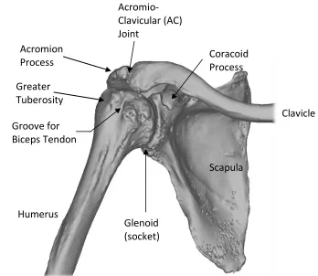
Figure 1.2: Bony anatomy of the shoulder joint
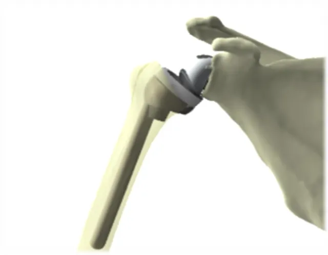
The humeral head is the most proximal surface of the humerus that articulates with the
glenoid fossa of the scapula. It is estimated as a partial sphere, however, is closer to an
ovoid shape, being longer in the superoinferior direction than the anteroposterior. It is
covered in cartilage for a smooth articulation.
The glenoid fossa is a shallow socket on the lateral side of the scapula, forming the second
half of the articulation couple comprising the glenohumeral joint. The glenoid surface is
close to conforming to the humeral head, but some mismatch in curvature is present. It is
also a small socket, covering only approximately a quarter of the humeral head. The low
level of bony constraint is a major factor in allowing the large range of motion of the
shoulder.
The scapula has two large bony prominences originating from the lateral superior section
of the bone, above the glenoid fossa. The coracoid process is the more anterior of the two
Scapula
Clavicle
Humerus Acromion Process
Greater Tuberosity
Groove for Biceps Tendon
Glenoid (socket) Acromio- Clavicular (AC) Joint
processes, and serves as an attachment point for various ligaments that stabilize the joint.
The acromion is the larger, posterior protrusion, which serves as a strut against the clavicle,
and provides as an attachment site for the deltoid muscle. Both the coracoid and acromion,
together with the ligaments that run between them, provide a superior mechanical stop to
limit the superior translation of the humeral head, and may limit abduction if the tubercles
are in a position to impinge on either the coracoid or acromion.
The superior part of the humerus has bony protrusions, known as the greater and lesser
tuberosities. They encompass most of the superior half of the humeral head, and provide a
nearly encompassing region for the insertions of the tendons of the rotator cuff, the primary
stabilizers of the glenohumeral joint. The tuberosities (and bicipital groove between them)
are also often used as surgical landmarks for implant positioning. The humeral shaft
(diaphysis) forms the long axis of the humerus, and is the distal insertion of the deltoid.
The joint capsule contains thickenings that have been defined as ligaments that include
three ligaments connecting the humeral head to the glenoid, wrapping around the anterior
side of the joint. On the superior aspect of the joint, the coraco-humeral ligament wraps
form the greater humeral tuberosity to the coracoid process.
Due to its relatively unconstrained geometry, the glenohumeral joint relies on muscles not
only for effecting motion, but also to compress the joint for stability. The relevant soft
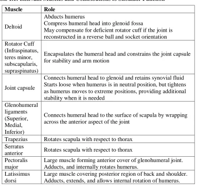
Table 1.1: Relevant Muscles and Contributions to Shoulder Function
Muscle Role
Deltoid
Abducts humerus
Compress humeral head into glenoid fossa
May compensate for deficient rotator cuff if the joint is reconstructed in a reverse ball and socket orientation Rotator Cuff
(Infraspinatus, teres minor, subscapularis, supraspinatus)
Encapsulates the humeral head and constrains the joint capsule for stability and arm motion
Joint capsule
Connects humeral head to glenoid and retains synovial fluid Starts loose when humerus is in neutral position, but tightens as humerus moves to extreme positions, providing additional stability when it is needed
Glenohumeral ligaments (Superior, Medial, Inferior)
Connects humeral head to the surface of scapula by wrapping across the anterior aspect of the joint
Trapezius Rotates scapula with respect to thorax Serratus
anterior Rotates scapula with respect to thorax Pectoralis
major
Large muscle forming anterior cover of glenohumeral joint. Adducts, and internally rotates humerus.
Latissimus dorsi
These structures are illustrated in Figure 1.3 below:
A SGHL MGHL
IGHL CAL
CHL
B C
D D
SS
SS
TM
TM
SC IS
Figure 1.3: Soft tissue structures of the shoulder
(A): Anterior view showing ligaments of the shoulder. CAL: Coraco-acromial ligament. CHL: Coraco-humeral ligament. SGHL: Superior Glenohumeral ligament. MGHL: Medial Glenohumeral ligament. IGHL: Inferior Glenohumeral ligament.
(B) Anterior view showing muscles of the shoulder. D: Deltoid. SS: Supraspinatus. Teres Minor. SC: Subscapularis.
1.2
Shoulder Instability
Chronic shoulder instability is characterized by excessive humeral head translation relative
to the glenoid, and may cause recurrent subluxation or frequent dislocations with minimal
dislocating force. Subluxation is defined by the humeral head resting in a partially
dislocated state, typically the humeral head is translated from the stable position where the
radial surfaces of the humeral head and the glenoid socket are concentric to a position
where the humeral head rests eccentrically in the glenoid. Instability is associated with a
loss of function of the joint due to joint pain, loss of range of motion, and apprehension or
the sensation that the shoulder may dislocate.
1.2.1
Causes of Shoulder Instability
Shoulder instability may be caused by deficient rotator cuff muscles, glenoid morphology,
or weakness in the muscles responsible for scapulothoracic motion.3–8
The rotator cuff is comprised of three muscle strands that wrap around the humeral head
and connect it to the scapula. The rotator cuff envelopes the joint and compresses the
humeral head into the glenoid as the arm moves. The combination of these functions makes
the rotator cuff the primary stabilizer of the shoulder joint. If the rotator cuff is weak or
damaged, it will be unable to properly constrain the humeral head to its centered, stabilized
position, contributing to shoulder instability. If the cuff cannot be repaired, the shoulder
will continue to be instable.
The morphology of the glenoid fossa is also related to joint stability. A normal glenoid
fossa, when viewed normal to the face, has a pear-shaped silhouette, with the inferior
portion approximating a perfect circle. Traumatic injury can alter the shape of the glenoid
rim, and cause irregularities in the inferior circularity. These irregularities have shown to
be present in up to 90% of traumatically induced instable glenohumeral joints.6,9 An intact
glenoid rim plays an important role to provide a small lip which prevents excessive humeral
head translation or subluxation. Additionally, instability is more likely if the glenoid is
tilted inferiorly,4,5 since the inferior lip is not in a position to provide a physical barrier for
If instability is caused by glenoid rim defects or repairable rotator cuff injury, surgical
treatments such as the Latarjet or Bankart procedures are usually successful in restoring
stability to the joint. 6,10,11 The Latarjet procedure repositions part of the coracoid and
attaches it as a bone graft to the anterior portion of the glenoid, to restore the bony rim of
the glenoid. The Bankart procedure involves suturing the joint capsule to the glenoid
labrum.12 While these surgeries are successful in restoring stability and range of motion in
most patients, recurring instability and apprehension is documented in up to 10% of
cases.12–14 Additionally, patients with a previous traumatic dislocation and surgical repair
are at a higher risk of developing arthritis in the joint,13,14 and may be candidates for joint
replacement as the arthritis progresses.
Shoulder arthroplasty aims to correct any abnormal glenoid morphology by reconstructing
the joint so that the humeral head curvature is centered and conforming to the glenoid
socket, but the success of the procedure will be dependent on surgical factors such as soft
tissue balancing, and proper position and orientation of the components.15
Another factor in glenohumeral instability is the movement of the scapula. As the arm is
abducted, the scapula also rotates upward, such that the glenoid fossa follows and supports
the humeral head through its arc of motion. Typically, there is a 2:1 ratio between
glenohumeral abduction and scapulothoracic rotation, which begins when the humerus is
abducted past 60°.3,16,17 This rotation allows the glenoid to follow the humeral head through
its arc of rotation and provide support from the inferior direction. The primary muscles
responsible for scapulothoracic motion (serratus anterior and trapezius) retract the superior
aspect of the scapula towards the midline of the body, allowing the humeral head to rotate
and occupy this space. Weakness in the serratus anterior and trapezius8 has been shown to
accompany anteroinferior instable shoulders as well as those with impingement
syndrome.18 Impingement syndrome is related to instability because in both these
conditions, the scapula is not sufficiently retracted to move the acromion process out of the
humeral head's path as it would be in a healthy shoulder.19 If these muscles are not strong
enough to affect the scapulothoracic rotation, the humeral head will not be adequately
1.3
Shoulder Arthroplasty State of the Art
One option for late stage shoulder pain or loss of function of the joint is the surgical
replacement of the articular surfaces with prosthetic components, a procedure known as
arthroplasty. Several implant designs are available and clinically used today.
1.3.1
Total Shoulder Arthroplasty
Total shoulder arthroplasty (TSA) is an effective treatment for several joint pathologies,
including osteoarthritis, rheumatoid arthritis, severe humeral fracture, or avascular
necrosis.20,21 In this procedure, the articular surface of the humeral head is resected per the
plane of the articular neck, the humeral canal is reamed, and a metal implant that replicates
the anatomic shape of the humerus is inserted, often cemented to fixate in place.22–25 On
the scapular side, the glenoid is reamed smooth, and small holes are drilled into the bone
for the fixation pegs, resulting in both articular surfaces replaced by prosthetic components.
A smooth polyethylene implant to create a smooth bearing surface is then cemented in
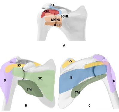
place. (Figure 1.4) TSA can restore pain free motion to the damaged shoulder, with
generally good outcomes reported if the rotator cuff is intact.26,27 However, in cases with a
deficient rotator cuff, a total shoulder arthroplasty can do little to restore motion or stability
of the shoulder, and in this case the recommended alternative is a reverse total shoulder
Figure 1.4: Total Shoulder Arthroplasty
Although an accepted treatment of shoulder pathology, in some cases the implant must be
revised due to complications such as humeral head migration after rotator cuff
degeneration, implant failure or malposition, infection or instability. Revision rates of TSA
are estimated at 10% after 10 years and 20% at 20 years.27 Schoch et al.29 report revision
rates of 17% after 15 years. Higher revision rates are associated with male gender (perhaps
due to higher loading of the joint), rotator cuff disease or tumors.27,30
1.3.2
Reverse Shoulder Arthroplasty
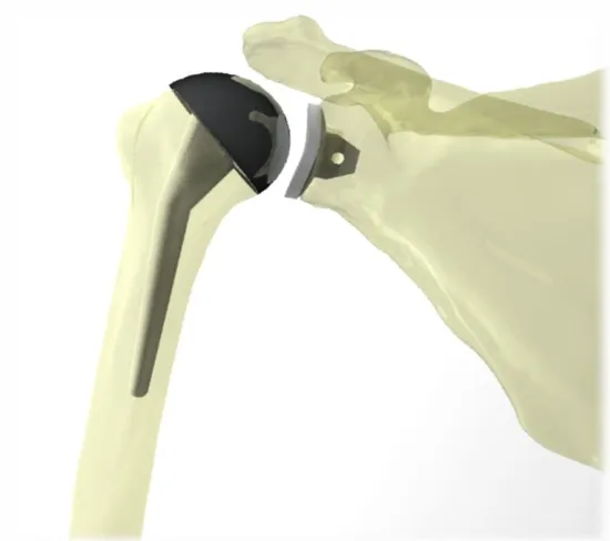
In a reverse shoulder arthroplasty (RSA), the surgical preparation is similar to a TSA, the
difference being the ball and socket are reversed. In an RSA, the ball (glenosphere) is fixed
to the glenoid, and the proximal humerus is removed and replaced with a polyethylene cup,
with an elongated shaft though the humeral canal (Figure 1.5). This results in a fixed joint
center of rotation, and allows the deltoid to replace the function of a deficient rotator cuff.
The indications for RSA include a prior failed TSA, deficient rotator cuff, arthritis, and
Figure 1.5: Reverse Shoulder Arthroplasty
Although the RSA has been used with success, and the prevalence of RSA is increasing
dramatically,34 it is not without complications.
The most common reported complication after an RSA is instability,32,35–41 with an
incidence of dislocation in up to 15% of RSA’s.32 Boileau et al.42 reported that nearly half
of all revision RSA surgeries were due to instability of the joint.42 This may be due to
inadequate deltoid tensioning, achieved through lateralizing the humeral component to
increase the offset of the center of rotation.38,43 Another potential factor in instability
following RSA is an irreparable subscapularis tendon. Edwards et al. 39 found the risk of
post-operative dislocation to be almost twice as high in patients with an irreparable
subscapularis tendon, compared to those with a repaired or intact tendon.39 Gallo et al.32
also found that an abnormal subscapularis was present in all cases with post-operative
dislocations as well as a compromised or absent greater tuberosity. However, Clark et al.44
found no difference in rates of dislocation between patients with an intact subscapularis
and patients without a repaired subscapularis and suggests the subscapularis does not have
Surgical management of recurrent instability after an RSA is limited, especially in revision
cases where glenoid bone quality is compromised.40,45 Chalmers et al. found that instability
rates for revised RSA’s were three times higher than in primary RSA cases.40 A second
revision surgery to manage chronic instability after an RSA was found successful in only
50% of cases,40 indicating a need for a new solution to chronic instability.
Due to the configuration of a reverse shoulder implant, arm motion is limited in the
allowable adduction range of motion. The inferior edge of the resected humerus may
impinge on the glenosphere when the humerus is adducted, resulting in an adduction
deficit. Because the CoR is medialized in an RSA, the humerus is displaced medially
towards the glenoid. When this medialization is combined with the geometry of the
glenosphere, the medialized humerus sits at the inferior edge of the glenosphere in
adduction, resulting in impingement. With repeated impingement in adduction, the
humeral cup wears away scapular bone directly inferior to the glenosphere.38,46,47 The
ability to restore humeral adduction is important for patient comfort, as this is a frequently
used position in activities of daily living.48,49
In conjunction with the loss of adduction range of motion and damage to the scapula
through scapular notching, a consistent and distinct wear pattern at the inferior aspect of
the humeral cup is observed in retrieved components from unsuccessful RSA’s.38,50 The
wear pattern indicates high stress concentrations that may be a result of unfavorable loading
conditions of this type of implant.50,51 This accelerated wear can lead to osteolysis, implant
loosening, or premature component failure and the need for revision surgery.
A key clinical indication for a RSA procedure is a deficient rotator cuff. The reversed ball
and socket configuration allows the deltoid to abduct the arm, a motion typically dependent
on rotator cuff function. However, limitations on the range of motion are identified, with
internal rotation affected by the size52 and positioning53 of the glenosphere.
1.3.3
Constrained Shoulder Reconstruction
In the case of severe fracture or joint reconstruction following tumor resection, insufficient
arthroplasty system. In this situation, more constrained shoulder prostheses are considered.
Due to the infrequent use of these implants, they may be custom-made for a patient.
Bayley Walker Implant (Fixed Fulcrum)
This model is a constrained reverse ball and socket joint or fixed fulcrum design, meaning
the socket encompasses more than half the sphere, similar to a traditional hip arthroplasty
system. It is recommended for reconstruction of the shoulder joint for recurrent instability,
revision joint arthroplasty, or following aggressive tumor resection in the joint.54 However,
this device has not been approved for use in the United States. It is worth noting that the
ball is popped into the socket and then held in place with a retaining ring, which is the
mechanism’s weak link and point of expected failure with a load that exceeds the design
load.55 The available range of motion is still limited, at two-thirds of a normal range of
motion.54
Custom Scapula and constrained joint reconstruction
In the case of high-grade sarcoma in the glenohumeral area, more bone than just the joint
surfaces must be replaced. A scapulectomy may be required, with some portion of the
proximal humerus resected as well. Typical commercially available modular shoulder
replacement systems do not provide for extended bone loss past the glenoid vault, or past
the humeral neck. In these situations, a custom implant may be required. Past cases have
documented the use of a frame reconstructed scapula with a constrained ball and socket
joint in a limited number of patients.56–58 A hollow scapular frame with holes through the
edges for muscular reattachment, combined with a locking ball joint has been used to
restore some functionality to the arm. This system requires intact musculature to both hold
the scapular prosthesis in place as well as to actuate humeral movement.56
Although this system can aid in the preservation of rotator cuff, it does not provide ideal
stability or sufficient range of motion to be considered fully successful. Long term viability
1.4
Revision Surgical Challenges
Although shoulder replacement is generally considered an effective treatment for end stage
shoulder arthritis, severe fracture, and osteonecrosis, there are some unsuccessful cases
where the implant must be removed and replaced (known as a revision). In the absence of
complications, it is generally accepted that a joint replacement should last approximately
15 years before it may need replacement.27,59 This timeline may be accelerated due to
infection, instability, loosening, or mechanical failure. Revision rates are estimated at 10%
after 10 years and 20% at 20 years.27 Higher revision rates associated with male gender
(perhaps due to higher loads placed on the joint), and rotator cuff disease or tumors.27,30
Due to a combination of low bone density, bone resorption and/or surgical damage to the
bone while removing the previous implants, there may be a lack of available quality bone
stock for good fixation of the new implant. Surgical damage often manifests itself as a large
cavitary defect, and may be on either the humeral or glenoid side. It is often a consequence
of revising a previous cemented implant; the bond of the cement mantle and implant is
stronger than the surrounding bone, so that the bone itself fractures first and some is
removed with the cemented implant.60,61 A contributing and related factor is bone
resorption due to stress shielding by the previous implant. Because the metals used for
implants are so much stiffer than the surrounding bone, the bone surrounding the implant
no longer carries the load. This causes an imbalance in bone remodeling such that more
bone is resorbed and new bone is not created.62–64
A lack of available bone stock is not only an issue for ensuring adequate fixation of the
implant to the bone, but it also suggests that some of the landmarks used for surgical
navigation and landmarks may not be available. This leads to difficulty positioning the
components in the absence of clinically relevant landmarks, such as the anatomic neck or
humeral tuberosities. Scalise et al.65 suggest that the implant may be positioned by
referencing the distance from the lateral edge of the acromion to the glenoid margin.65
Alternatively, several studies have found a correlation with the contralateral shoulder and
suggest using it as a guide when anatomic landmarks are unavailable on the affected
A final challenge in revision surgery is the possibility that the rotator cuff or other soft
tissues may not be intact. The rotator cuff, as the primary stabilizer of the joint, is a key
structure for effecting anatomic motion. It may be damaged by the surgical incisions from
a previous procedure,69 damaged because of improper sizing of a prosthetic component,
trauma induced injury, or disease. These soft tissue structures are needed for joint stability
and ambulation of a ball and socket joint.
1.5
Development of a Linked Shoulder Implant
Universal joints (also known as Cardan joints, Hooke’s joints, Spicer joints) allow
rotational motion and torque to be transmitted between two shafts that are not co-linear.
(Figure 1.6) While the universal joint is not a recent invention – the first record of its use
was a variation based on gimbals by the ancient Greeks for the ballasts of ships – its modern
form comprised of perpendicular pins and yokes are still in use today and are credited to
Robert Hooke in 1667 for a sundial.70 The most common modern application may be for
automotive driveshafts, allowing torque to be transmitted to propel the vehicle, while also
providing forgiveness for misaligned input and output shafts. In addition to its widespread
use in automotive driveshafts, universal joints are also found in many industrial
applications, hand tools, robotics, etc.
Figure 1.6: Torque transmitting universal joint (pin and block style)
Universal joints are rated based on the combined requirements of operating angle,
maximum speed, and maximum torque. There is an inverse relationship between operating
angle and allowable torque; a larger shaft misalignment lowers the allowable torque
Center Trunnion Pin
Yoke
transmission. A similar penalty-based relationship exists between the rated speed and the
remaining factors. Commercial literature for universal joints allows for joint angles up to
a maximum of 45°, with a torque transmission rating penalty that rises proportionally with
the mismatch angle between input and output shafts. To increase the joint angle, a double
universal joint can be used, with the understanding that rated torque capacity and shaft
rotation speed must decrease by at least a factor of two. The driveshaft efficiency decreases
as joint angle increases.
1.5.1
Design Objectives and Rationale for a Universal Joint
Implant
The new design for a linked implant was modelled after a universal joint to replicate its
large range of motion, along with its smoothness of motion for higher quality mo vement.
Unlike the traditional application of universal joints to transmit torque between
non-collinear shafts, the universal joint implant has a third revolute joint to allow internal and
external rotation of the humerus. The introduction of this swivel also minimizes the torque
on the glenoid fixation, which is identified as a potential failure mechanism.
Typical applications of universal joints include automotive driveshafts, where high speed,
low torque and low joint angles are expected. In contrast, the application for a shoulder
implant requires a universal joint to allow a large joint angle, with low speed, and minimal
torque transmission. It must however, be capable of resisting both bending stress, contact
stress, and fatigue.
The linked shoulder implant will be subjected to frequent bending stress, with the
magnitude varying depending on the loading case. Thus, it is worth considering both the
loading data generated from the instrumented traditional shoulder hemiarthroplasty as well
as knowledge about the loading and contact patterns of hip implants. Metal on metal
articulating surfaces are no longer used due to the complications associated with the wear
particles generated from surface contact stresses. The wear particles generated can
contribute to bone resorption and ultimately implant loosening as the encompassing bone
the small size of components of a universal joint, the components would need to be made
of a strong, stiff metal to withstand the loads placed on the joint.
Due to the sphere on sphere contact geometry of a ball and socket joint, by Hertzian contact
theory, the theoretical contact area is an infinitely small point. However, in reality, there is
some deformation whenever a load is applied, resulting in a patch of contact with some
area. The same theory states that the theoretical contact pattern of two concentric cylinders
would be a line, which in reality would turn into an ellipse as the surfaces deformed slightly
under loads. This larger contact area distributes the force, thereby decreasing the contact
stress at the surface. This reduces stress concentrations which in turn reduces the likelihood
of developing scratches and premature excessive wear on the articulating surfaces of a pin
and block style universal joint.
A second layer of protection against the negative effects of wear particles is encapsulating
the implant linkage within a flexible silicon boot (or sleeve). This is a common technique
for a universal joint driveshaft that operates in a dirty environment, and keeps dirt and grit
out of the mechanism, and can be filled with lubricant to minimize friction between
surfaces. In a medical implant application, the purpose of the sleeve would be to keep any
wear particles within the boot, as well as keep the joint lubricated.
1.6
Thesis Rationale
Despite advances in joint arthroplasty components and surgical techniques, a small subset
of patients continues to experience chronic subluxation and instability of the shoulder,
impairing their ability to perform basic activities of daily life. Existing prostheses have
limited ability to restore both stability and normal range of motion to the shoulder,
especially in cases of severe stabilizing soft tissue deficit. A universal joint, by virtue of its
linked components, cannot dislocate, and thus could provide intrinsic stability to the joint.
It allows three rotational degrees of freedom, necessary to replicate the motion of the
shoulder.
No linked universal type joints have been investigated for use in shoulder arthroplasty. It
ability of the implant and its fixation to withstand the expected loads of the shoulder. The
purpose of this project is to design a novel linked implant for the shoulder that can achieve
full range of motion while providing intrinsic stability to the joint. The feasibility of this
implant design will be computationally evaluated with a basic parametric design, ahead of
any experimental models.
1.7
Objectives and Hypotheses
The primary objective of this work was to develop a universal joint linkage as a shoulder
prosthesis, and evaluate its feasibility and performance in context of the requirements for
activities of daily living. The design requirements were based on healthy shoulders, with
the goal of restoring normal function to a compromised joint. The joint’s performance was
assessed on three criteria, forming the pillars of this research project. The corresponding
hypothesis directly follows each objective.
Objective 1:
Design a parametric linked shoulder implant. The implant design should include variable
parameters to create an array of configurations that may be computationally tested in order
to determine which configuration affords superior three-dimensional range of motion.
Hypothesis 1:
Normal range of motion can be achieved by some configuration of a universal joint linked
implant.
Objective 2:
Determine the stresses experienced by the components of the designed linked implant in
physiologically relevant joint loads using finite element analysis. These stresses are to be
Hypothesis 2:
The joint components will be capable of withstanding the expected stresses with a wide
margin of safety.
Objective 3:
Evaluate the bone stresses experienced at the glenoid fixation interface by comparison of
different implant configurations with variable lateralization distance of the center of
rotation.
Hypothesis 3:
Bone fixation stresses will increase based on lateralization distance of the center of
rotation, but stay within the allowable limits of bone strength.
1.8
Thesis Overview
Chapter 2 presents the development of the basic implant design and identifies the variable
parameters of its configuration. After generating an array of implant configurations, the
circumduction range of motion for each configuration was measured to determine the
configuration that allows the greatest range of motion. After determining a basic
configuration, Chapter 3 will confirm component design feasibility in terms of static yield
and fatigue failure criteria. Chapter 4 will investigate relative bone failure risk due to the
increased bending moment generated from this novel linked implant design. Finally,
chapter 5 provides an overall summary and discussion of the findings of this research, and
Chapter 2
2
Range of Motion of a Linked Shoulder Implant with
Variable Configurations
OVERVIEW: Quantification of the allowable circumduction range of motion is an
important metric to determine the success of restoring shoulder motion. A parametric implant model was created and several parameters (proximal yoke orientation, tilt, and
location, offset distance of the two revolute joints of the implant) were varied for a total of twenty-four unique configurations. A standardized computational testing protocol was developed to test each of the implant configurations. A partial spherical surface that
represents the allowable circumduction range of motion was developed to provide a visual representation for comparison of parameters to select the optimal configuration to
maximize range of motion.
2.1
Development of a Universal Joint Shoulder Implant
To restore full motion in the glenohumeral joint, especially in the case of compromised
bony anatomy or soft tissue, the joint mechanism must be inherently stable and constrained.
Common universal joint designs were used as a starting point. Applications include
automotive driveshafts or socket set drivers. While capable of transmitting high levels of
torque, the joint angle is limited to 45° in any direction for a commercial universal joint.
The geometry of the yokes lends additional strength to the joint, but at the expense of the
range of available motion. Additionally, the geometry of the center trunnion plays a role in
the range of motion; a flat cross provides less range of motion than an offset pin and block
center trunnion. Each component of the universal joint shoulder implant is described in the
2.1.1
Universal Joint Components
Components for the proposed universal joint implant are illustrated in Figure 2.1 below.
Detailed drawings of each component can be found in Appendix B.
Figure 2.1:Components of proposed linked universal joint implant
Yokes
The yokes provide a frame to hold each pin, and form a hinge joint together with the center
trunnion. The yokes must be strong enough to withstand bending stresses, but also
sufficiently cantilevered to allow a large range of motion. There must also be a mechanism
to connect the base of each yoke to its mated counterpart - ie. the glenoid baseplate and
humeral shaft.
To accomplish the above requirements, yokes with a rectangular profile were used. The
aspect ratio and radius were adjusted to allow clearance with the center trunnion at its
maximum joint angle. A filleted rectangular cross-section was also used to prevent
impingement with the center trunnion as it rotates through the axis at the base of the yoke.
Humeral Shaft
Pin
Humeral Yoke
Center
Trunnion Glenoid Yoke
Glenoid Baseplate
Center Trunnion
The center trunnion articulates with the pins to allow two orthogonal rotational degrees of
freedom, and withstands axial compression transmitted from the humeral yoke to the
glenoid yoke. A pivot pin and block style was used for its high strength to size ratio.
The hinge joints of the trunnion were laterally offset to allow for clearance as the humeral
component travels around the fixed glenoid component. A pin and block assembly was
used, with the interface between the pins and block considered to act as journal bearings
under compression.
Pins
Two identical pins were created to connect the center trunnion to each yoke. The tolerance
was selected to be a press fit with the yoke hole, and a close running fit with the holes in
the center trunnion. This will allow the ends of the hinge to remain constrained, and provide
free, low friction articulation with the surface of the center trunnion.
Humeral Shaft
The humeral shaft was designed to fit around the base of the humeral yoke for a third
rotational degree of freedom to replicate native internal and external rotation, as well as
minimize the torque transmitted to the glenoid. An additional feature is its greater length
compared to standard total and reverse shoulder arthroplasty systems’ humeral stems. This
will allow greater fixation in poorer quality bone, as is expected in revision surgery cases,
or patients with low bone density.
Glenoid Baseplate
The universal joint trunnion must be fixed to the glenoid to provide a stable fulcrum for
the joint motion. The success of the glenosphere fixation in reverse shoulder arthroplasty
using a baseplate and bone screws has been studied as the use of RSA’s have increased.61,75– 77 The lateralized abduction hinge of the universal joint implant is expected to show a
similar loading pattern on the glenoid fixation to that of a lateralized offset glenosphere of
offset RSA glenosphere (DJO RSP).25 A circular baseplate was used with a domed back to
closely fit against a reamed glenoid. The central screw is 6.5 mm diameter, and 25 mm in
length, with 4 peripheral captured screws of the same length, but 4.5 mm in diameter.76
An additional benefit of using an established design is in the case of revision surgery from
a RSA to the proposed linked shoulder implant; if the existing glenoid baseplate is intact
and well-fixed, it can be used with the linked implant system, minimizing the surgical
damage to the patient and preserving glenoid bone quality.
Protector Sleeve for Implant
At the articulation of each joint, the resulting contact stress causes wear. Wear debris from
metal and polyethylene components can cause complications in patients. It is associated
with osteolysis, which may lead to pain and stiffness in the joint.38,63,73,78
In typical mechanical applications for a universal joint in a driveshaft, the joint surfaces
can be protected using a bellowed boot.79,80 This protective boot both preserves lubrication
on the articulating surfaces and prevents dirt and grit from entering the joint and
contributing to early wear acting as third body particles.
Replicating this concept with a biocompatible silicone boot can prevent any metal debris
from escaping into the body, preventing adverse reactions as well as providing the
opportunity to use materials typically excluded from consideration due to
bio-incompatibility or bio-reactivity. A final benefit is the ability to keep lubrication in the joint
to reduce friction and therefore also reduce wear.81,82
This thesis describes the design of a linked implant which is intended to be used in
conjunction with a protective boot. While the design of the boot itself is outside the scope
of this thesis, it is important to ensure that appropriate materials exist for this application
and are currently used for a variety of medical implant applications. Examples include
materials such as Elasthane,83 CarboSil,84 and BioNate,85 with documented use as an
insulative encapsulation for neuro-electrical stimulator implants, which would otherwise
be toxic to the body. Additionally, tough, flexible materials (ie.- CarboSil,84 BioSpan,86 or
use, such as artificial heart pumps and valves. These materials are demonstrated to be
biocompatible and bio-inert, safe for use as long-term implanted medical devices.
Therefore, the design of the implant itself proceeds with the knowledge that appropriate
booting materials and technology exists. The design of the boot is considered future work
after evaluating the feasibility of a linked shoulder implant.
2.2
Development of Virtual Prototype
Several iterations of a universal joint were made in 3D CAD software (SolidWorks 2017,
Dassault Systems, France) with varying geometries: a Y-yoke joint with a crossed center
trunnion (Figure 2.2), a square yoke with a flat trunnion, and a square yoke with an offset
center trunnion. The square yoke with an offset center trunnion provided the greatest range
of motion. The next step was to adjust the dimensions such that the center trunnion was
free to swivel about both pins without impinging on the base of the yokes. This involved
longer yokes than typically seen in driveshaft torque transmitting designs to allow a larger
rotational range of motion around each pin. While this would be a concern for the additional
torsional stress on the yokes in a driveshaft application, since there is a third revolute joint
on the humeral shaft, there is minimal torque transmitted through the joint. One caveat to
the square yoked design with an offset center trunnion is that the joint is not capable of
moving in a continual hemispherical motion; at the equator of motion, the joint must retract
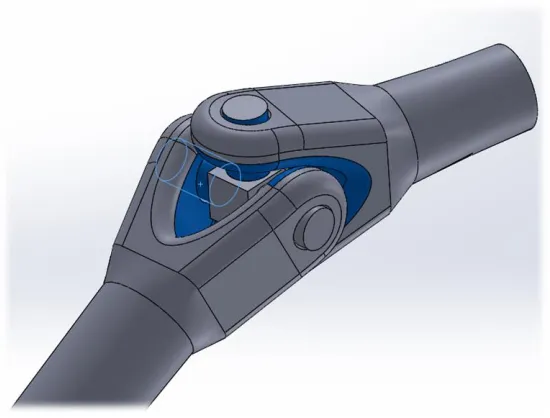
Figure 2.2: Y-yoke universal joint
Range of motion limited by impingement between proximal and distal yokes. (Impingement shown in blue highlighted faces).
The third revolute joint is added to provide the arm with internal/external rotation and
minimize torque transmitted to the glenoid. This could be located on either the proximal or
distal side of the trunnion. The revolute joint was incorporated into the humeral shaft for
more intuitive user motion, as it would replicate natural humeral internal/external rotation
more closely. Additionally, the longer shaft to fix the humerus in place lends itself
seamlessly to a sleeved revolute joint.
With a basic linkage model created, it could be virtually implanted into a bone model.
Different parameters in linkage geometry as well as the implantation technique could be
varied to sift out the combination that affords the greatest range of motion.
2.3
Virtual Implantation of Universal Joint Implant into
Bony Geometry
A full-arm bone model was created from the bone density threshold of a CT scan of a
cadaveric scapula and humerus. The donor was an 85 year old male (height: 165 cm,
weight: 67 kg). The bones were segmented using a semi-automatic algorithm (Mimics
between the transepicondylar axis and the scapular plane).87 Reference geometry was
created to provide consistent landmarks for positioning the implant. Points were placed
along the glenoid rim, and a best fit plane was created from the points using a least squares
algorithm. This will be referred to as the glenoid plane. Bisectors connecting the superior
and inferior points of the glenoid rim, and anterior-posterior were created to form the center
point of the glenoid dish. With this reference geometry in place, the glenoid yoke could be
positioned appropriately. The center of the glenoid yoke was coincident with the center of
the glenoid face, and the edges of the yokes could be set parallel or perpendicular to the
superoinferior bisector to control the glenoid yoke orientation. (Figure 2.3)
Figure 2.3: Positioning of the glenoid baseplate
The antero-posterior and supero-inferior bisectors of the glenoid are shown as black lines. The intersection of these bisectors represents the center of the glenoid face. The glenoid baseplate shown is lowered 5 mm from the center of the glenoid face (blue line).
The humeral head resection plane was placed by an experienced fellowship trained
shoulder surgeon (GSA), based on surgical landmarks of the anatomic neck. The virtual
osteotomy was performed aggressively – the osteotomy plane was translated 5 mm more
distal than for a traditional shoulder arthroplasty. This had a noticeable effect on the range
plane restricted internal and external rotation, and caused earlier impingement with the
superior portion of the humeral head with the glenoid yoke at less than 90° of abduction
relative to the glenoid face. Only the cortical bone was considered, such that the humeral
yoke was set in a hollow humeral head, resembling a large contained cavitary defect, a
common occurrence in revision surgery.60
The native shoulder has a center of rotation that can be calculated from the landmarks of
the humerus and glenoid fossa.88 Custom code (Matlab 2016a, MathWorks, Massachusetts)
was used to extract the center of the best fit sphere of the humeral head, which
approximated by the geometric center of rotation.89 The linked implant was initially
positioned such that the center of mass of the 6 mm offset center trunnion (midpoint
between pins) was coincident with the geometric center of rotation of the native humeral
head. For the default orientation, the medial face of the glenoid yoke was mated parallel
and coincident to the glenoid plane.
For parameter variation, the tilt of the glenoid component was adjusted using specified
angular relationships between the medial face of the glenoid yoke and the glenoid plane.
The location of the lowered glenoid component was set so its center was 5 mm inferior to
the center of the glenoid face.90
The humeral stem was aligned with the center of the canal circle fit for the proximal third
of the humerus to replicate current surgical techniques.23,24,91
2.4
Parameter Variations
First, the parameters to be varied were identified, along with their levels of variations.
Variation was set at discrete increments since kinematic functions have not been developed
for an offset center trunnion universal joint. The goal of the implant is to maximize the
available range of motion, while still ensuring its mechanical integrity and preventing
dislocation of the joint. Common surgical practices for the implantation of RSA, a
semi-constrained prosthesis, suggest the lateralization offset of the CoR, tilt of the glenoid
component, and position of the glenoid all contribute to the available ROM and the
The parameters to be varied were:
• Glenoid Yoke Orientation
• Glenoid Yoke Position
• Glenoid Yoke Tilt
• Offset Distance of Center Trunnion
As described in the following sections.
Glenoid Yoke Orientation
The arms of the glenoid yoke were oriented to be either horizontal or vertical relative to
the face of the glenoid (Figure 2.4). This may influence the lever arm of the deltoid muscle;
as the location of the horizontal pin joint moves more distal/lateral, the deltoid moment
arm will be shortened, resulting in a higher required muscle force to abduct the arm.
Medializing the horizontal pin joint may lengthen the lever arm for the deltoid, making the
deltoid more effective in abducting the arm. This could be evaluated by muscle force
balance analysis. However, muscle contributions and force analysis are outside the scope
of this project.
Figure 2.4: Glenoid yoke orientation variation
Glenoid Yoke Position
The glenoid yoke was located either in the center of the glenoid face, determined by the
intersection of the anteroposterior and superoinferior bisectors, or lowered 5 mm from the
center (Figure 2.5). A common surgical technique in a reverse shoulder arthroplasty is to
position the glenosphere so that it is tangent to the inferior portion of the glenoid. This
provides two key benefits – it helps avoid scapular impingement and puts additional tension
on the deltoid to give it a mechanical advantage as it is replacing the function of the rotator
cuff.38,43,53 Ladermann et al found that lengthening the humerus tended to result in a more
stable shoulder.43
Figure 2.5: Glenoid yoke position variation
Glenoid Yoke Tilt
The tilt of the glenosphere is another variation currently under investigation for the reverse
shoulder arthroplasty technique. It is thought that an inferior tilt helps maximize available
range of motion by preventing scapular notching. An additional benefit is additional deltoid
lengthening, which increases the lever arm of the deltoid, providing a mechanical
advantage to the muscle.38,43 As such, three different tilts were investigated with the linked
shoulder implant: neutral, 10° inferior, and 20° inferior (Figure 2.6). A superior tilt was not
used – preliminary testing (performed using the protocol described in 2.3) showed that a
superior tilt increased the incidence of scapular impingement, so it was not pursued further.
Figure 2.6: Glenoid yoke tilt variation
Offset Distance of Center Trunnion
Varying the offset distance of the center trunnion displaces the centers of rotation of the
two joints created by the linked universal joint design. While a larger offset distance
between the two joint centers may achieve a larger range of motion, the moment arm for
the deltoid should be considered. Additionally, lateralization of the humerus in reverse
shoulder arthroplasty designs may contribute to lowering joint and muscle loads, as well
as decreasing the incidence and severity of scapular impingement.52
Figure 2.7: Offset distance of hinge joints in center trunnion variation
Left: 6 mm offset between center and hinges in the center trunnion (C6). Right: 8 mm offset between center and hinges in the center trunnion (C8). Both share a vertically oriented, centered, neutral tilted glenoid yoke. (VG_C_N)
An additional consideration is that the patient may encounter some proprioceptive changes
because of the joint’s non-anatomical geometry. In changing from a ball and socket joint configuration to a universal joint configuration, there may be discomfort in the user’s
perception of the dual center of motion, and that coincident supplementary motions are
now required to achieve the intended motion. (The user must reposition the implant around
the yokes by backing off and then reaching back out again). However, clinical testing of
this implant is outside the scope of this thesis, and requires FDA approval so any changes
in proprioception due to the dual centers of rotation will not be known until clinical trials.
To investigate the effects of the offset distance of joints on range of motion, two different
to the center of the pin of 6 mm and 8 mm (Figure 2.7). The 8 mm offset distance would
result in a net lengthening of the humerus by 4 mm compared to the 6 mm offset, and
provide an extended reach around the yokes.
2.5
Range of Motion Testing Protocol
With four parameters identified to be varied per their respective levels, range of motion
testing could be performed.
The humerus was manually moved to the extremes of motion for the full circumduction
range,92,93 using the collision detection function (SolidWorks). We checked for
impingement in both bone-on-bone contact and bone-on-implant contact. Once a collision
was detected, the joint was moved back slightly to a position with no impingement and the
position of the midpoint of the transepicondylar axis was recorded. The humerus was
axially rotated to an orientation that would minimize bony impingement and allow a larger
joint angle, by retracting the superior portion of the humeral head to the side. A template
was overlaid to the scapula on each model to ensure consistency in the rotational spacing
of the humerus. (Figure 2.8) The template had thirty spokes, so that when the
transepicondylar midpoint was aligned with each spoke, each position recorded was
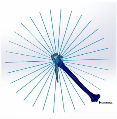
Figure 2.8: Range of motion template
View is orthogonal to the glenoid face. Humerus is shown aligned with one of the spokes of the range of motion template. Once the humerus was aligned with a spoke, it was then rotated toward the glenoid until impingement was detected.
Once all circumduction range of motion points had been plotted, a surface was created,
bounded by the lines connecting each placed circumduction point and the geometric center
of rotation of the native humeral head. Knitting each of these surfaces together resulted in
a 3D boundary of motion, which was then used as a cutting tool to cut out the available
boundary out of a sphere to depict the allowable range of motion for each implant
configuration (Figure 2.9). The boundaries of motion are recorded, without concern of the
contributing kinematics. Humeral rotation is incorporated into the measurements, rather
than reported separately.
These partial spheres were then overlaid on top of each other and the assembly to determine
which configurations provided the most range of motion. This setup also allowed direct
comparison of which configurations allowed the greatest joint angles in specific
movements. For example, determination of which configuration allows the greatest
adduction before impingement is quick and obvious.
This protocol was first done for all configurations on a medium specimen which also had
average head-neck and retroversion angles.94,95 Sizing of cadaveric specimens was
determined based on humeral length. (Donor information given in Table 2.1) Based on the
results of the full study, this protocol was repeated for six specific configurations in both a
small specimen and a large specimen to elucidate the range of motion of the universal joint
linkage itself, rather than the effects of differing bone morphology of a single specimen.
These additional specimens incorporated a wider humeral retroversion angle range.
Table 2.1: Anthropometric data of specimens used for range of motion testing
Specimen Specimen ID
Sex Weight (kg) Height (cm) Humeral Length (cm) Age (years) Head-Neck Angle (°) Version Angle1 (°)
Small 09-05059R F 60 157 280 66 129 42
Medium 14-07032R M 67 165 320 85 137 35
Large 11-01002R M 101 178 345 58 137 11