ALL-OPTICAL TUNABLE MIRROR DESIGN USING ELECTROMAGNETICALLY INDUCED
TRANSPARENCY
K. Abbasian, A. Rostami, and Z. D. Koozehkanani†
Photonics and Nanocrystal Research Lab. (PNRL) Faculty of Electrical and Computer Engineering University of Tabriz
Tabriz 51664, Iran
Abstract—A new and efficient proposal for all-optical tunable devices and systems using electromagnetically induced transparency (EIT) is proposed. For this purpose a slab doped with quantum dots for realization of three-level atomic system is considered. Density matrix formulation for evaluation of the proposed structure is used. The reflection and transmission coefficients of the considered slab are calculated and the related amplitude and phase quantities studied versus parameters of the structure. We show that some nanometer tuning with application of the control field is obtained. So, the proposed idea can open a new realization method of all-optical tunable devices and systems towards all-optical systems.
1. INTRODUCTION
High-speed communication and computing are basic industrial and academic research demand recently. Optical engineering is one of the best alternatives for realization of these purposes. One of key operation in developing of complete optical engineering domain is suitable proposal for tunable device design. In conventional optical engineering there aren’t all-optical tunable devices and systems. So, in this paper, we try to propose this operation for the first time from our point of view.
In this part some of presented papers in this field are reviewed. Basic principles of EIT and applications of this phenomenon were discussed in [1–5]. In these papers applications of EIT in optical filter
design was considered too. Also, a nonlinear optical property in slow light regime was studied.
Application of the EIT in design of high resolution (sub-nanometer) displacement optical sensor was discussed in [6]. In this paper the authors have been shown that using 3-level atoms doped into ring resonator the sensitivity of the optical displacement sensor can be increased.
For description of the quantum optical nature of light propagation through media including 3-level atoms density matrix method incorporating classical light and quantum mechanical particles are needed which was discussed in [7–14].
Optimal control of light propagation through 3-level atoms was discussed in [15]. In this paper interference between the control and probe fields were used for group velocity control of the probe field.
Finally optical mirror design for vertical cavity surface emitting laser diodes was discussed in [16, 17]. Finally, selective optical pumping for introducing selective reflection spectrum was discussed in [18]. It should mention that some papers published by one of authors recently illustrate that considering shape of quantum dots, nonlinear coefficients and dipole moments can be increased several order of magnitudes, which can be used for easy all-optical device design [19–21].
In [22] high precision displacement sensor based on electromagnet-ically induced transparency (EIT) was presented. In this paper using EIT ultra-high-precision was reported. In [23] transparency in Meta materials was considered. Finally transparency in optical sensor design was applied in [24].
Thus there isn’t a practical method for implementation of tunable devices and systems. So, we decided to propose a new design for mirror using electromagnetically induced transparency. We considered a slab doped with quantum dots implemented 3-level artificial atoms. Density matrix method is used for theoretical evaluation of the optical properties of the proposed slab as mirror. Using developed mathematical method the reflection coefficient (amplitude and phase) is calculated. Considering the obtained result it is observed that both amplitude and phase of the reflection coefficient can be controlled that is used for realization of all-optical devices and systems.
Organization of the paper is as follows:
2. MATHEMATICAL BACKGROUND
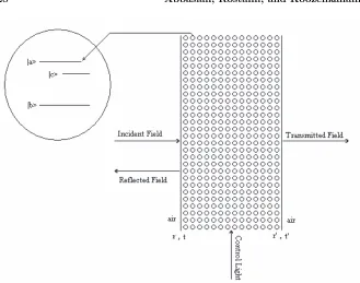
The proposed structure for all-optical tunable mirror is illustrated in Fig. 1. It is shown that the proposed structure includes a slab doped with 3-level nanocrystals which is operates as optical mirror applicable for optical devices and systems. As an example one can consider Si-nanocrystals doped in silica matrix. Schematically the probe field is applied to the slab horizontally from the left side and a control field is applied from the bottom. Now, in the following, with doping of 3-level particles (as an example in this work, other discrete energy structures can be considered too) such as suitable quantum dots inside slab, we obtain the reflection and transmission coefficients based on the Maxwell’s equations. Also, the light propagation through the proposed slab is modeled. First, we consider normal (without EIT) slab inserted between air layers in the following structure for simplicity. The presented relation generally manages the system parametrically and can be applied to EIT case with considering the refractive index of the slab with calculated real part of the optical susceptibility. For calculation of optical susceptibility of slab, quantum optical density matrix method is used. In the following, we review some basic relation illustrating the reflection and transmission coefficients of single layer homogeneous and isotropic media.
According to basic concepts in classical optics and relations in homogeneous, linear and isotropic media the following relations are presented for the reflected and transmitted parts of incident light. First, we introduce two basic relations defining the phase difference of light wave propagating through the media and conservation of the reflection and transmission coefficients as follows:
δ= 2πnrL
λ , (1)
r =−r
r2+tt+α= 1 , (2)
where δ, nr, L, λ, r, r, α, t, t and R = |r|2 are the phase
difference of probe light (incident light), the real part of refractive index for proposed slab, medium length, incident wavelength, the reflection coefficient of interfaces from left, the reflection coefficient of interfaces from right hand side, optical loss coefficient in the interface, the transmission coefficient of interfaces from right hand side and intensity reflection coefficient of the slab interface respectively.
Figure 1. Schematic of the proposed all-optical tunable mirror (medium with quantum dot dopants).
phases.
ER = EI
r(1−ei2δ)
1 −R ei2δ , (3)
ET = EI tt
1−R ei2δ, (4)
where ER, ET, EI and δ are the reflected, transmitted, incident
electric fields and the gained phase delay during propagation in the slab length respectively. So, absolute value of the transmission coefficient and phase can be extracted as follows:
|tE| = ET
EI
=
(1−R−α)
(1−Rcos 2δ)2+ (Rsin 2δ)2
(1−Rcos 2δ)2+R2sin22δ , (5)
ϕET EI
= tan−1 Rsin 2δ
where R = |r|2. For the reflection coefficient the similar method can be used and the following results are obtained.
|rE| = ER
EI
=
((1 +R) (1−cos 2δ))2+ ((R−1) sin 2δ)2
(1−Rcos 2δ)2+R2sin22δ ,(7)
ϕER EI
= tan−1
R−1 1 +R cotδ
, (8)
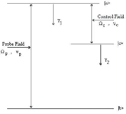
Now, we develop the mathematical method to describe effect of parameters of 3-level particles added in the considered slab on optical characteristics of the designed device (mirror). Fig. 2 shows the model of 3-level particles including the probe and control fields and decay rates. In this figure the control and probe fields applied between c, a
and b, a levels respectively. Due to applied control field the optical characteristic is changed and in the following, theoretical calculation for description of the proposed system is presented.
Figure 2. Schematic of 3-level Λ type atom doped in slab waveguide.
Hamiltonian and density matrix are given as follows.
H =
ωb 0 −
℘abε
2 eiυpt 0 ωc −12Ωceiϕceiυct −℘abε
2 e−
iυpt −1
2Ωce−
iϕce−iυct ω a
, (9)
ρ =
ρbb ρ˜∗cbeiωcbt ρ˜∗abeiωabt
˜
ρ∗cbe−iωcbt ρ
cc ρ˜∗aceiωact
˜
ρ∗abe−iωabt ρ˜∗
ace−iωact ρaa
, (10)
whereωa, ωb, ωc, γab, ε, υp, υc, φc and Ωc =℘acεc/are frequencies
corresponding to three levels, decay rate between levels a and b, amplitude of the probe field (V/m), probe field frequency, control field frequency, control field phase and Rabi frequency of the control field respectively. ωcb, ωabandωacare frequencies corresponding to energies
between levels in the presented model. Based on the time development equation of density matrix [6] with differential motion equations and assuming appropriate boundary conditions the following matrix form of equations can be obtained [7].
˙
R =−M R+A (11)
with
R =
˜
ρab
˜
ρcd
, (12)
M =
i∆ +γ1 −2iΩce−iϕc −i
2Ωce
iϕc i∆ +γ
2
, (13)
A =
i℘abε/2
0
, (14)
where γ1 and γ2 are decay rate of density matrix elements of ρab and ρcb. Also, Ωc, ℘ab and ∆ are the Rabi frequency of the control field,
dipole moment element between a and b levels and detuning of the probe field from resonance frequency, respectively.
So, optical susceptibility can be obtained with manipulation of the relationship between polarization and dipole moment element as follows.
χ= P
ε0E
= 2Na℘ 2ρ
ab ε0Ωp
, (15)
where Ωp and Na are the Rabi frequency of the probe field and the
optical loss or gain and induced index of refraction using from the real and imaginary parts of the susceptibility can be found as follows.
α = κ
2χ
, (16)
δn = nχ
2, (17)
whereχ, χ, κ andn are the real and imaginary parts of the optical susceptibility, wave number and refractive index respectively.
3. SIMULATION RESULTS
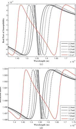
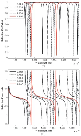
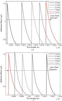
In this section numerical investigation of the proposed structure including the reflection and transmission coefficients and spectral behavior of the proposed device are done. First, we consider effect of the applied control field on optical susceptibility, refractive index and optical loss which is shown in Fig. 3, and then investigate effect on magnitude and phase of the reflection coefficient which is illustrated in Fig. 4. It is well known that with increasing the control field EIT window is broadened where optical loss coefficient goes to zero and slope of refractive index decreases. We show that with change of control field (illustrated in the figure legend) the magnitude and phase of the reflection coefficient are changed at given wavelength. So, with applying the control light, optically tunable capability of the proposed mirror is obtained and illustrated in both below and above regions of EIT window.
Figure 4 shows that with increasing magnitude of the control field, the reflection profile is shifted to long wavelengths. This effect can be described in terms of upper level splitting more with increasing the control field. On the other hand with increasing the control field upper energy level splits more and the probe field with smaller energy can be absorbed. Thus the resonant wavelength shifts to long wavelengths. The magnitude and phase profiles of the reflection coefficient for different magnitudes of the control field are shown in Fig. 5. It is shown that with change of the magnitude of control field the magnitude and phase of reflection coefficient of the probe field is changed that is excellent for realization of all optical tunable devices and systems.
In Fig. 5, we observed that with increasing magnitude of the control field, the magnitude and phase of the reflection coefficient increase in below region of resonant wavelength (wavelengths smaller
1.4 1.45 1.5 1.55 1.6 1.65 1.7 1.75 x 10⁻⁶ 0
1 2 3 4 5 6 7 8 9 10
x 10-3
Wavelength (m)
Im
aginar
y
P
a
rt
o
f
S
u
sc
ep
ti
b
ilit
y
2.34e6 3.75e6 5.31e6 7.65e6 1.3 e7
(a)
1.4 1.45 1.5 1.55 1.6 1.65 1.7 1.75 x 10⁻⁶ 0
0.5 1 1.5 2 2.5 3
x 104
Wavelength (m)
Opti
ca
l
L
o
ss
(1
/m
)
2.34e6 3.75e6 5.31e6 7.65e6 1.3 e7
1.45 1.5 1.55 1.6 1.65 1.7 x 10⁻⁶ -5
-4 -3 -2 -1 0 1 2 3 4 5
x 10-3
Wavelength (m)
Real
P
a
rt
o
f
S
u
sc
ep
ti
b
ilit
y
2.34e6 3.75e6 5.31e6 7.65e6 1.3 e7
(c)
1.4 1.45 1.5 1.55 1.6 1.65 1.7 1.75 x 10⁻⁶ 1.496
1.497 1.498 1.499 1.5 1.501 1.502 1.503 1.504
Wavelength (m)
R
ef
rac
ti
on
In
de
x
2.34e6 3.75e6 5.31e6 7.65e6 1.3 e7
(d)
Figure 3. Optical susceptibility, refractive index and loss vs.
wavelength and control field amplitude as a parameter. (a) Imaginary part of optical susceptibility, (b) optical loss, (c) real part of optical susceptibility and (d) refractive index. Ep = 10 V/m, Na = 7.5 ×
than resonant wavelength) while those quantities decrease in above region (wavelengths larger than resonant wavelength). So, wavelength tuning ranges for below and above regions are shown in Fig. 6. Two parts of Fig. 6 shows wavelength tuning ranges with slab lengths of 100, 200, 300 and 400 microns versus control field amplitude. In the
1.544 1.5445 1.545 1.5455 1.546 1.5465 1.547 1.5475 1.548 1.5485 x 10⁻⁶ -1.5
-1 -0.5 0 0.5 1 1.5
Wavelength (m)
R
efl
ec
ti
o
n
P
ha
se
(
ra
d)
2.34e6 3.75e6 5.31e6 7.65e6 1.3 e7
(b)
1.544 1.5445 1.545 1.5455 1.546 1.5465 1.547 1.5475 1.548 1.5485 x 10⁻⁶ 0.1
0.2 0.3 0.4 0.5 0.6 0.7 0.8 0.9 1
Wavelength (m)
R
efl
ec
ti
o
n
C
o
ef
fi
ci
en
t
2.34e6 3.75e6 5.31e6 7.65e6 1.3 e7
1.55 1.551 1.552 1.553 1.554 1.555 1.556 x 10⁻⁶ -1.5
-1 -0.5 0 0.5 1 1.5
Wavelength (m)
R
efl
ec
ti
o
n
P
h
a
se
(r
a
d)
2.34e6 3.75e6 5.31e6 7.65e6 1.3 e7
(d)
1.55 1.551 1.552 1.553 1.554 1.555 1.556 x 10⁻⁶ 0
0.1 0.2 0.3 0.4 0.5 0.6 0.7 0.8 0.9 1
Wavelength (m)
R
ef
lect
io
n
C
o
ef
fi
ci
en
t
2.34e6 3.75e6 5.31e6 7.65e6 1.3 e7
(c)
Figure 4. Reflection coefficient (magnitude and phase of probe field) vs. wavelength and the control field amplitude as a parameter. (a) magnitude, (b) phase (radiant) in below and (c) magnitude, (d) phase (radiant) in above regions of resonant wavelength. Ep = 10 V/m, Na = 7.5 × 1016cm−3, γ1 = 5 × 10¹¹s−1, γ2 = γ3 = 107 s−1,
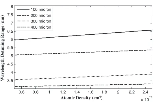
following effect of atomic density on maximum obtainable tuning range of the proposed mirror is studied and result is illustrated in Fig. 7. It is observed that with increasing the atomic density the maximum wavelength tuning range is increased proportional, which is measured in outside of EIT window.
Also, Fig. 7 shows the wavelength tuning range of the magnitude
1.551 1.5512 1.5514 1.5516 1.5518 1.552 x 10⁻⁶ 0.1
0.2 0.3 0.4 0.5 0.6 0.7 0.8 0.9 1
Wavelength (m)
Ref
lect
io
n
Co
ef
fi
ci
en
t
2.34e6 3.75e6 5.31e6 7.65e6 1.3 e7 Cont. Field Increases
(a)
1.5464 1.5466 1.5468 1.547 1.5472 1.5474 1.5476 1.5478 x 10⁻⁶ 0
0.1 0.2 0.3 0.4 0.5 0.6 0.7 0.8 0.9 1
Wavelength (m)
R
efl
ec
ti
o
n
C
o
ef
fi
ci
en
t
2.34e6 3.75e6 5.31e6 7.65e6 1.3 e7 Cont. Field Increases
1.5511 1.5512 1.5513 1.5514 1.5515 1.5516 1.5517 1.5518 1.5519 x 10⁻⁶ 0.5
1 1.5
Wavelength (m)
R
efl
ec
ti
o
n
P
h
a
se
(r
a
d.
)
2.34e6 3.75e6 5.31e6 7.65e6 1.3 e7
Cont. Field Increases
(c)
1.5466 1.5468 1.547 1.5472 1.5474 1.5476 1.5478 x 10⁻⁶ 0.5
1 1.5
Wavelength (m)
Re
fl
ec
ti
o
n
P
h
as
e
(r
a
d)
2.34e6 3.75e6 5.31e6 7.65e6 1.3 e7
Cont. Field Increases
(d)
Figure 5. Magnitude and phase of the reflection coefficient of
probe field vs. wavelength. (a) and (b) in below region of resonant wavelength, (c) and (d) in above region of resonant wavelength. Ep =
10 V/m, Na = 7.5×1016cm−3, γ1 = 5×10¹¹s−1,γ2 =γ3 = 107 s−1,
0 1 2 3 4 5
x 10-4 2 4 6 8 10 12
x 106 0 1 2 3 4
x 10-3
Slab Length (m) Control Field Amp. (V/m)
Wave le n g th T u ning R a n g e (m ic ro n ) Up 100 Low 100 Up 200 Low 200 Up 300 Low 300 Up 400 Low 400 (a) 0 1 2 3 4 5
x 10-4 4
6 8 10 12
x 106 1.535 1.54 1.545 1.55 1.555 1.56 1.565 1.57
Slab Length (m) Control Field Amp. (V/m)
Wave le n g th ( m ic ron
) Up 100
Low 100 Up 200 Low 200 Up 300 Low 300 Up 400 Low 400 (b)
0.6 0.8 1 1.2 1.4 1.6 1.8 2 2.2 2.4 x 10¹⁷ 3.5
4 4.5 5 5.5 6 6.5 7 7.5 8
Atomic Density (cm )
W
a
v
el
eng
th
D
et
uning
R
a
n
g
e
(n
m
)
100 micron 200 micron 300 micron 400 micron
-3
Figure 7. Tuning range of the reflection coefficient vs. control field and slab length. Ep= 10 V/m,Na= 7.5×1016cm−3,γ1 = 5×10¹¹s−1,
γ2 =γ3= 107 s−1,℘ab = 5×10⁻⁹ e-cm, R= 0.75,L= 3×10⁻⁴m.
and phase of the reflection coefficient for different slab lengths. It is observed that for atomic density variation from 5×10¹⁶ to 2.5× 1017cm−3 the wavelength tuning range changes about %5 from 5.98, 5.066, 3.56, 3.14 to 6.585, 5.37, 3.899, 3.21 nanometer for slab lengths of 100, 200, 300, 400 microns, respectively.
4. CONCLUSION
In this paper all-optical tunable device and system operation principle based on the EIT phenomenon has been proposed for first time. In this case as an example optical mirror which has applications in semiconductor lasers is considered. We have shown that with change of the control field the reflection coefficient including amplitude and phase are changed. In this paper, we considered a slab including three-level quantum dots for realization of Λ-type atoms for EIT process and find about 4 nm tuning range in EIT window where optical loss is negligible.
REFERENCES
1. Rostami, A. and K. Abbasian, “All-optical filter design: Electromagnetically induced transparency and ring resonator,”
2. Zhu, K.-D. and W. S. Li, “Electromagnetically induced transparency due to exciton-phonon interaction in an organic quantum well,” J. Phys. B: At. Mol. Opt. Phys., Vol. 34, L679– L686, 2001.
3. Harris, S. E. and L. V. Hau, “Nonlinear optics at low light levels,”
Phys. Rev. Lett., Vol. 82, 4611, 1999.
4. Harris, S. E., “Electromagnetically induced transparency,”
Physics Today, 36–42, July 1994.
5. Agrawal, G. P., Nonlinear Fiber Optics, Academic Press, 0-12-045143-3, 2001.
6. Yadipour, R., K. Abbasian, A. Rostami, and Z. D. Koozehkanani, “A novel proposal for ultra-high resolution and compact optical displacement sensor based on electromagnetically induced transparency in ring resonator,” Progress In Electromagnetics Research, PIER 77, 149–170, 2007.
7. Scully, M. O. and M. S. Zubairy, Quantum Optics, Cambridge University Press, ISBN: 0 521 43458 0, 2001.
8. Petrosyan, D. and Y. P. Malakyan, “Electromagnetically induced transparency in a thin film,”IEEE, QWD3, 2000.
9. Kasapi, A., M. Jain, G. Y. Yin, and S. E. Harris, “Electromagnet-ically induced transparency: Propagation dynamics,” Phys. Rev. Lett., Vol. 74, 2447, 1995.
10. Fleischhauer, M., “Electromagnetically induced transparency and coherent-state preparation in optically thick media,” Optics Express 107, Vol. 4, No. 2, January 1999.
11. Kimberg, V., “Pulse propagation in photonic crystals and nonlinear media,” Master Thesis, Royal Institute of Technology, Stockholm, Sweden, 2005.
12. Slavcheva, G., J. M. Arnold, and R. W. Ziolkowski, “Ultrashort pulse lossless propagation through a degenerate three-level medium in nonlinear optical waveguides and semiconductor microcavities,” IEEE Journal of Selected Topics in Quantum Electronics, Vol. 9, No. 3, 929–939, May/June 2003.
13. Grigoryan, G. G. and Y. T. Pashayan, “Propagation of pulses in a three-level medium at exact twophoton resonance,”Physical Review A, Vol. 64, 013816, June 2001.
14. Arkhipkin, V. G. and I. V. Timofeev, “Long distance propagation of resonant pulses under conditions of induced transparency,”
IEEE, QTHF3, 2000.
A, Vol. 52, No. 1, July 1995.
16. Stomeo, T., M. T. Todaro, G. Visimberga, V. Vitale, A. Passaseo, R. Cingolani, M. DeVittorio, A. D’Orazio, M. De Sario, V. Marrocco, V. Petruzzelli, F. Prudenzano, S. Cabrini, and E. Di Fabrizio, “Design of two-dimensional photonic-crystal mirrors for InGaAs QW laser applications,” Microelectronic Engineering, Vol. 73–74, 377–382, 2004.
17. Linnik, M. and A. Christou, “Effects of Bragg mirror interface grading and layer thickness variations on VCSEL performance at 1.55 mm,” Department of Materials and Nuclear Engineering and Center for OptoElectronic Devices, Packaging and Interconnects (COEDIP), University of Maryland, College Park, MD 20742. 18. Gross, B., N. Papageorgiou, V. Sautenkov, and A. Weis, “Velocity
selective optical pumping and dark resonance in selective reflection spectroscopy,”Physical Review A, Vol. 55, 2973.
19. Rostami, A., H. Rasooli, and H. Baghban, “Proposal for ultra high performance infrared quantum dot,”Optics Express, Vol. 16, No. 4, 2008.
20. Rostami, A., H. Baghban, and H. Rasooli, “Highly-enhanced second-order nonlinear susceptibility in tailored GaN-AlGaN-AlN quantum well structures,” Accepted for publication inPhysica B, 2008.
21. Rostami, A., H. Rasooli, and H. Baghban, “Enhancement of absorption coefficient and electroabsorption in GaN/AlGaN centered defect quantum box (CDQB) nanocrystal,” Accepted for publication inPhysica B, 2008.
22. Yadipour, R., K. Abbasian, A. Rostami, and Z. D. Koozehkanani, “A novel proposal for ultra-high resolution and compact optical displacement sensor based on electromagnetically induced transparency in ring resonator,” Progress In Electromagnetics Research, PIER 77, 149–170, 2007.
23. Dai, X.-W., M. Yao, X.-J. Dang, and C.-H. Liang, “Transparency of a pair of epsilon-negative slab and mu-negative slab,”Progress In Electromagnetics Research, PIER 69, 237–246, 2007.