ELASTIC PROPERTY EVALUATION OF HOT STRUCTURAL
COMPOSITES USED IN RE-ENTRY SPACE MODULES
Shinto Baby, Dept. of Mechanical Engineering,Amal Jyothi College of Engineering, Kerala, India Simil T.S, Scientist/Engineer, CCTD/CMSE/VSSC/ISRO, Vattiyoorkavu, Kerala, India K.G. Samuel, Professor & Head, Dept. of Metallurgy, AmalJyothi College of Engineering, India
Abstract- Composites hot structures are used for the
realization of re-entry space module systems which experiences elevated temperature regimes during the re-entry phase. Carbon-Carbon and Carbon-Ceramics are the most preferred composites for this application.Mechanical properties evaluation of the above materials at the simulated service conditions is always a challenging task. The tailor made high temperature mechanical test system is currently being used for evaluation of the mechanical strength of these composites at simulated service temperature conditions ranging from 600 to 2000° C.A novel video gauging system has been introduced to evaluate the strains and modulus of the above materials at the elevated temperature scenarios. This non-contact strain /modulus evaluation system tracks the pixel movements in a video which is captured during the tests. Soft computing based pattern recognition and feature matching techniques are used for the same.Evaluation of the above video gauging system is carried out by performing mechanical tests on different composites materials at ambient conditions. Results from the strain gauges used for these tests were compared with the video gauge results to verify its accuracy and repeatability. With the confidence gained from these tests, the video gauging system has been employed to evaluate strains /modulus of Carbon-Carbon and Carbon-Ceramic specimens at a temperature range of 300 to 1200ºC.The architecture of the video gauging system, details of tests conducted and analysis of tests results are presented.
Keywords: Composite hot structures, Carbon-Carbon
composites, Carbon-Ceramic composites High
temperature mechanical testing, Non-contact strain evaluation, Video gauging.
I. INTRODUCTION
Composites hot structures are the apt choice for thermo-structural systems used re-entry space vehicles and modules. Design of composites structures in general and hot structural composites in particular is always a challenging task which needs in depth knowledge in the physical and mechanical
properties of raw materials and elements used for composites realization [1].
Newer techniques are being evolved out in evaluating the mechanical properties of composites. One of them is the non-contact strain monitoring methods [2]. Even though this method in use for the last couple of decades, difficulty in measuring low strains kept this technique at bay in case of high modulus materials especially composites. But with the advent of software and image processing technology, this method has improved with many variants [3]. Video gauging is one of them which is very effective when considering the tradeoff between the accuracy and processing capability. The same is chosen for evaluating strains and modulus of hot structural composites for India’s re-entry space module development.
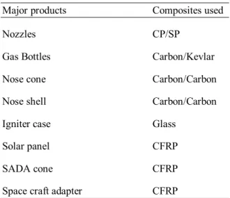
II. TYPES OF COMPOSITES SPECIMEN USED FOR SPACE APPLICATION
Major products Composites used
Nozzles CP/SP
Gas Bottles Carbon/Kevlar
Nose cone Carbon/Carbon
Nose shell Carbon/Carbon
Igniter case Glass
Solar panel CFRP
SADA cone CFRP
Space craft adapter CFRP
Table 1 Types of composites specimen used for space application
III. HOT STRUCTURAL MATERIALS Carbon fiber-reinforced carbon (carbon– carbon, abbreviated C/C) is a composite material consisting of carbon fiber reinforcement in a matrix of graphite [6]. It was developed for the nose cones of intercontinental ballistic missiles, and is most widely known as the material for the nose cone and wing leading edges of the Space Shuttle orbiter. It has been used in the brake systems of Formula One racing cars since 1976; carbon–carbon brake discs and pads are a standard component of Formula One brake systems. Carbon–carbon is well-suited to structural applications at high temperatures, or where thermal shock resistance and/or a low coefficient of thermal expansion is needed [10]. While it is less brittle than many other ceramics, it lacks impact resistance; Space Shuttle Columbia was destroyed during atmospheric re-entry after one of its RCC panels was broken by the impact of a piece of foam insulation from the Space. This catastrophic failure was due in part to original shuttle design requirements which did not consider the likelihood of such violent impacts.
Ceramic matrix composites (CMC), based on reinforcements of carbon fibers and matrices of silicon carbide (called C/SiC or C/C-SiC composites) represent a relatively new class of structural materials. In the last few years new manufacturing processes and materials have been developed [4]. Short fiber reinforcements, cheap polymer precursors and liquid phase processes reduced the costs by almost one order of magnitude in comparison to first generation C/SiC composites which were originally developed for space and military applications [8]. Besides high mass specific properties and high thermal stability, functional properties like low thermal expansion and good tribological behavior play an increasing importance for new commercial applications like brake disks and pads, clutches, calibration plates or furnace charging devices [7].Carbon fiber-reinforced silicon carbide (C/SiC) is a development of pure carbon–carbon, and can be used in automotive applications, such as components of systems on high performance road cars, namely the brake disc and brake pads. C/SiC utilizes silicon carbide with carbon fiber, and this compound is thought to be more durable than pure carbon–carbon [5].
IV. VIDEO GAUGING
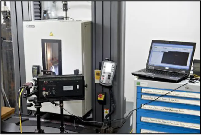
magnitude more accurate than our competitors. It uses pattern recognition and sub-pixel interpolation to measure the exact displacements of selected points in an image [9]. Targets are tracked in real time, outputting measurements frame-by-frame. This technology allows for non-contact multi-point measurements of strain, rotation and displacement. A resolution better than 1/200,000 of the visible area is achievable, giving strain resolution of 5 micro strain. The system is so straightforward that after a half-day’s training any user can obtain accurate modulus measurements of carbon composites or displacement resolutions of 0.1mm on a bridge load test. Video gauging test set-up is shown in figure 1.
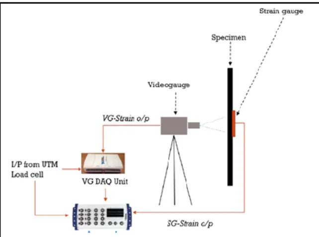
Fig. 1 Video gauging test set-up
Video gauge’s engineers build systems using the highest quality components, including precision mechanics and optics, as well as cameras with resolutions from VGA to 12 megapixel and speeds from 1 frame / second to over 1 million frames / second. The real core of what makes video gauge systems an order of magnitude more accurate than Video Gauges competitors is the processing algorithms that developed.The software uses pattern recognition and sub-pixel interpolation to make measurements to identify the exact location of a user-defined target in the image. It tracks the pattern at user-defined locations frame-by-frame, outputting the corresponding measurement data in real time. The principles involved in this technique are often referred to as Digital Image Correlation (DIC), although what video gauge does is way beyond what you will find in a textbook on DIC. The system has been independently benchmarked to be an order of magnitude more accurate than other image-based measurement systems, and even the entry-level version achieves class B2 ASTM E83 calibration for 0.1 – 1% extensions (accuracy better than 0.5%).
Displacement Distance Angular rotation Material properties
2D Strain (Tension, Compression, Shear) Poisson’s ratio
Stress/strain curve Modulus
V. STRAIN EVALUATION AT ELEVATED TEMEPRATURES
The high temperature test facility is composed by the major modules viz. 1) Universal Testing Machine (UTM), 2) Thermal chamber 3) Water Cooling System 4) Power supply and control system and 5) Data Acquisition. The UTM is equipped with fixtures and accessories for conducting tension, compression, shear, bending and inter laminar shear (ILSS) tests. The thermal chamber is integrated on to the UTM base. Thermal chamber consists of movable graphite heating elements which are supported and electrically powered by water cooled copper bars. Water channels cut on the chamber body enables cooling water circulation with a high flow rate per minute. The power control unit has the capability to deliver a high current to the heating elements. A safety console constantly monitors the power output, the water temperature, the water flow rate and is equipped with auto cut off systems. The temperature is monitored and captured by the pyrometer and associated data acquisition system. The overall architecture of the test facility set up is illustrated in figure 2.A universal testing machine (UTM), also known as a universal tester, materials testing machine or materials test frame, is used to test the tensile stress and compressive strength of materials.An environmental chamber is an enclosure used to test the effects of specified environmental conditions on biological items, industrial products, materials, and electronic devices and components.The pyrometer can be of two types, either fixed-mount or portable. Fixed mount units are generally installed in one location to continuously monitor a given process.
Fig. 2 High temperature test facility
VI. EVALUATION OF VIDEOGAUGING SYSTEM
Evaluation has been done by conducting room temperature tests on various composite specimens. The specimens were bonded with strain gauges on the flat face. Video gauging measurements were carried out on the opposite face. Both data were captured and compared. Most of the cases a perfect match was observed. Wherever there was a difference reason for the same has been investigated and found out. With this confidence video gauging system was employed for high temperature tests. Evaluation using video gauging system is shown in figure 1.
VII. TEST RESULTS AND DATA ANALYSIS Our aim was to evaluate modulus at elevated temperature ranging up to 1200°C. To accomplish this initially we had to evaluate the Video gauging system by comparing its results with the results from the strain gauges. Hence a series of Room temperature (RT) tests were carried out on different composites materials.We have conducted tensile & shear tests at room temperature. The tensile test method is designed to produce tensile property data
for material specifications, research and
development, quality assurance, and structural design and analysis. Factors that influence the tensile response and should therefore be reported include the following: material, methods of material preparation and lay-up, specimen stacking sequence, specimen preparation, specimen conditioning, environment of testing, specimen alignment and gripping, speed of testing, time at temperature, void content, and volume percent reinforcement.
VIII. TENSION TEST AT ROOM TEMPERATURE (ASTM D 3039)
Different composite materials such as carbon-epoxy, carbon-ceramic, aramid-twaron etc. were tested at room temperature using strain gauges and the results were compared with the results obtained from video gauge.
Sl.
No. Specimen Material/ Standard Gauge Strain Modulus (GPa) Video Gauge Modulus (GPa) 1. Carbon-Epoxy 68.44 59.59 2. Carbon-Epoxy 116.8 103.7 3. Carbon-Epoxy 109.1 107 4. Carbon-Epoxy 355.2 333.8 5. Carbon-Epoxy 333 348.7 6. Carbon-Ceramic 56.51 66.9 7. Carbon-Ceramic 56.6 62.5 8. Carbon-Ceramic 69.8 77.4 9. Carbon-Ceramic 54.9 47.1 10 Carbon-Ceramic 62.2 63.2 11. Carbon-Ceramic 75.6 75.6 12. Aramid-Twaron 16.5 16.0 13. Carbon-Carbon 52.6 46.9
Table 2 Comparison of modulus values obtained from Strain gauge and video gauge results at room
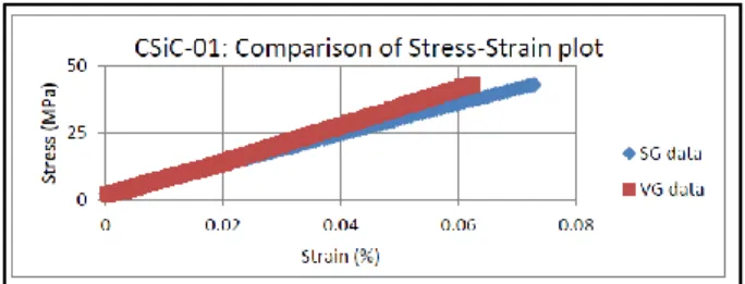
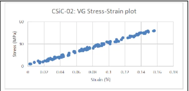
Fig. 4Comparison of Stress-Strain plot of CSiC composite
Figure 4 shows the comparison of Stress-Strain plot of CSiC composite at room temperature.The above graph shows the stress-strain plot of Carbon-Ceramic composite. From the above data we have proved that the results obtained from the Video gauge and Strain gauge has a close match. With this confidence we have carried out the high temperature tests.
IX. TENSION TEST AT HIGH TEMPERATURE Composite materials of carbon-carbon, carbon-ceramic and graphite materials were tested at a temperature ranging from 300° C to 1200° C. the results are shown below. An example of high temperature modulus evaluation of carbon-ceramic material using video gauging is shown in figure 5.
Sl.
No. Specimen Material/ Test Temp. Gauge Video Modulus (GPa) 1. Carbon-Carbon/300° C 90.61 2. Carbon-Carbon/500° C 74.75 3. Carbon-Carbon/600° C 73.92 4. Carbon-Carbon/700° C 66.16 5. Carbon-Carbon/1100° C 69.70 6. Carbon-Carbon/1100° C 50.90 7. Carbon-Carbon/1200° C 44.10 8. Carbon-Ceramic/850° C 20.80 9. Carbon-Ceramic/900° C 30.60 10. Carbon-Ceramic/1000° C 28.60 11. Graphite/1100° C 07.00 12. Graphite/1200° C 05.10
Table 3 Evaluation of modulus values obtained from Video gauge results at high temperature
Fig. 5Stress-Strain plot of CSiC composite at high temperature
X. CONCLUSION
Hot structural composite materials used for the realization of thermo structural systems in re-entry space vehicles/modules requires evaluation of their elastic properties at service conditions including elevated temperature regimes.Traditional techniques for strain / modulus evaluation viz. strain gauges, extensometers etc can’t be used for elevated temperature conditions. Hence the video gauging based non-contact strain/modulus evaluation systems which is found apt for the above mentioned application has been employed.To evaluate the performance of video gauging system elastic properties were evaluated at room temperature on various aerospace composite materials. The results were analyzed with respect to the same obtained from strain gauges. With the apprehension and confidence gained from these tests, video gauging system has been used for evaluating properties at elevated
temperatures on hot structural composite
materials.The high temperature environment causes problems in accomplishing noise free images for the video gauging system. The same has been rectified through smart choice of lenses & filter mechanism. Tests were done up to 1200 ºC and results were analyzed.
XI. AKNOWLEDGEMENT
Authors wish to acknowledge Director, VSSC and Deputy Director, Engineer in-charge,Composites Entity, VSSC for permission to publish this paper.We wish our thanks to engineers and technical assistants of Mechanical Testing Lab, VSSC for their efforts put for completing testing and analysis.
REFERENCES
1. G. Rohini Devi et al “Carbon-Carbon Composites -An Overview”. Defence Science Journal, Vol 43, No 4, October 1993, pp 369-383.
2. W. Kreakel et al “C/C-SiC Composites for space application and advanced friction systems”. Material science and engineering-A, Vol 412, Issues 1-2, December 2005, Pages 177-181. 3. Joshua C. Walls et al “High temperature
compression testing of an advanced carbon-carbon composite in an oxidizing atmosphere”. 4. S.R. Dhakate et al “High temperature tensile
properties of 2D cross-ply carbon-carbon composites”. Advanced materials letters, 2011, 2(2), 106-112.
5. Simil T.S. et al “Study on Mechanical Properties of Carbon-Carbon Composites Developed for Aerospace Applications”. Composites Entity, Vikram Sarabhai Space Centre, ISRO, Trivandrum, India
6. Peng Xiao et al “Preparation, Properties and Application of C/C-SiC Composites Fabricated by Warm Compacted-in situ Reaction”. J. Mater. Sci. Technol., 2010, 26(3), 283-288.
7. Rosario Gerhardt et al “Properties and
Applications of Silicon Carbide”.
InTechJanezaTrdine 9, 51000 Rijeka, Croatia. 8. Daniel Gay et al “Composite materials design
and applications”. CRC Press Boca Raton London New York Washington, D.C.
9. Bing Pan et al “Two-dimensional digital image correlation for in-plane displacement and strain measurement: a review”. Meas. Sci. Technol. 20 (2009) 062001 (17pp).
10. M D Bond et al “Full - field strain measurement
of notched discontinuous carbon fiber
composites”. Polymer Composites Group, Division of Materials, Mechanics and Structures, The University of Nottingham.