Simulation of Hybrid inverter with fuzzy logic controller for
distributed generators applied to unbalanced loads
L.Srinivas M-tech Student Scholar
Department of Electrical & Electronics Engineering, NarasimhaReddy Engineering College, Maisammaguda;
RR (Dt); Telangana, India. Email:[email protected]
P.Prasanna Kumari Assistant Professor
Department of Electrical & Electronics Engineering, NarasimhaReddy Engineering College, Maisammaguda;
RR (Dt); Telangana, India. Email:[email protected]
Abstract-Micro grids are small-scale electricity supply networks that have local power generation. Micro grid became one of the key spot in research on distributed energy systems.Micro grids are capable of both generating their own electric power with small-scale distributed generation (micro sources) and receiving/exporting power to the main
utility grid. In this paper
a control strategy for inverter based MG which can ensure stability and proper power sharing among the inverters, in islanded mode, is proposed. A MG can be operated in two modes, grid connected and islanded mode. Each mode has its own control strategy. Microgrid (MG),
mainly inverter based, are gaining more and moreimportance as they can accommodate various types of DGs effectively and for their superior power quality. A MG can be operated in two modes, grid connected and islanded mode. Each mode has its own control strategy. The general control philosophy within a micro grid is that sources must rely only on local information, yet must cooperate with other sources. To accomplish that goal, the proposed controller uses droop characteristics for active-power/frequency and reactive-power/voltage. The proposed control strategy is based on the use of a phase locked loop to measure the micro grid frequency at the inverter terminals, and to facilitate regulation of the inverter phase relative to the micro grid. This control strategy allows micro grids to seamlessly transition between grid-connected and autonomous operation, and vice versa. The controller has been implemented in an actual micro grid that incorporated multiple sources.The main objective of the proposed controller is to inject a clean sinusoidal current to the grid, even in the presence of nonlinear/unbalanced loads and/or grid-voltage distortions. The repetitive control technique is adopted because it can deal with a very large number of harmonics simultaneously with fuzzy logic controller by using Matlab/Simulink.
Key words-Distributed generation, 3-leg inverter, 4-leg inverter, unbalanced load.
I. introduction
In recent years, eco-friendly distributed generationsystems (DGS) such as wind turbines, solar cells, and fuelcells are dramatically growing because they can fulfill theincreasing demand of electric power due to the rapid growthof the economy and strict environmental regulationsregarding greenhouse gas emissions. Generally, the DGSsare interconnected in parallel with
the electric utility grid andprovide maximum electric power to the grid. However, thereare some areas (e.g., remote islands or villages) where theconnection to the grid is expensive or impractical and thensmall scaled standalone DGSs are the only efficient andeconomical options. In such DGSs, depending on consumers‟power demand, there are situations where some DGSsoperate in parallel or independently. In either case, a stableoperation of each DGS unit is as important as the stability ofthe parallel operating DGSs in which the proper load sharingof each unit is one of main research issues since the voltagecontroller is commonly used in a single DGS unit or multipleDGS units. For this reason, the voltage controller design for asingle DGS unit, which can guarantee a good voltageregulation under unbalanced and nonlinear loads, is aninteresting topic in the field of the DGSs control.
Fig.1: 3-leg inverter with split DC link capacitor.
Nevertheless this is the most popularly usedtopology for 3-phase, 4-wire DG system. Both the topologiesfail while feeding a 3-phase, 4-wire unbalanced load. Hence additional unbalanced load compensators are usually providednear the unbalanced load end. However with the advent of 4-leg inverters (see Fig.3),it is possible to handle unbalanced loads without affectingterminal voltages [6], [7]. The load neutral can be connected to the center of fourth leg and zero sequence currents flowingthrough neutral can be controlled.
Fig.2: 3-leg inverter interface with -Y transformer.
Fig.3: 4-leg inverter.
Advantages of 4-leg inverterinterfaces are as follows:
There are no ripples in DC link voltage when 4-leginverters cater to unbalanced or nonlinear loads. So thereis no need of large DC link capacitors as is the case of3-leg split DC link topology.
The 3-dimensional Space Vector Modulation (3-D SVM)technique enhances the utilization of (3-DC link voltage [8].
Presence of fourth neutral leg eliminates the requirementof bulky transformers for power evacuation (at least insmall low voltage stand-alone DG systems).
The 4-leg inverters are widely used as active load compensators[9], [10]. The capability of using 4-leg inverter as an interfacefor stand-alone microgrid with unbalanced load is discussedin [11]. Its application to handle emergency mode for lineinteractive system is discussed in [12]. But all the existing DGsystems are working with 3-leg inverter interfaces. Howeverwhile expanding the existing system, the possibility of using4-leg inverter interface needs to be explored. This idea isaddressed in detail in this paper. This is a novel way to mitigate the load unbalance by forming hybrid inverter interfacesinstead of local unbalance compensators. The proposed DGsystem with 3-leg and 4-leg inverter interfaces is shown in Fig.4.
Fig.4: DG system with 3-leg and 4-leg inverter interfaces.
In this paper, we are presenting the work carried out in designing the Fuzzy logic controller for switchingoperation of inverter. A simple control strategy of inverter is adopted where the measurement. Then the performances ofconventional fuzzy logic controller are investigated. Simulation results show that Total Harmonic Distortion in sourcecurrent is drastically reduced fuzzy controller is included in the inverter control circuit.
Simulation work has been doneusing
MATLAB/SIMULINK software.
II. CONTROLLER DESIGN FOR 3-LEG AND 4-LEG INVERTERS
(1)
Where Vm is peak value of phase voltage and Vdc
is the DClink voltage. For 230V rms phase voltage, Vm is 325V. Withm = 1, DC link voltage required is 563V. But to take careof losses, it is maintained at 580V. For closed-loop designof each inverter, terminal voltages of inverters, load currentsand capacitor currents are sensed. These are transformed intosynchronous reference frame to form a decoupled closed-loopsystem. It is to be noted here that for 3-leg inverters, there areonly q-axis and d-axis controllers (see Fig.5). This is because3-leg inverters have only two degrees of freedom (DOF). Onthe other hand, a 4-leg inverter has three DOFs and there areq-axis, d-axis and 0-axis controllers [14] (see Fig.6).
Fig.5: Closed-loop system for 3-leg inverter interfaced DG system.
Fig. 6.Closed-loop system for 4-leg inverter interfaced DG system.
For decentralized operation, P -f and Q-V droop laws areapplied. Thus there is no communication required betweenthe two DG units. For generating references for inner voltagecontrol loops, frequency and amplitude of voltages is generatedby droop laws.
The transformation ratio of ∆-Y transformer used in 3-leginverter interfaced system is 1:1 for the sake of simplicity. Insimulation, renewable energy source of DC link is replaced by3-phase diode bridge rectifier. All the simulations are carriedout using MATLAB Simulink
III. POWER FLOW ANALYSIS IN HYBRID DG SYSTEM
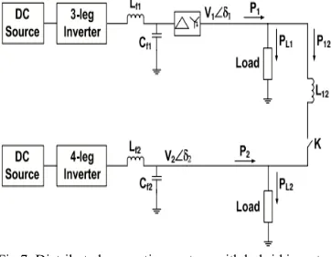
For understanding the power flow in interconnecting line,the single line diagram of DG system with hybrid inverter interfaces is shown in Fig.7. In this section, analysis of powerflow in interconnecting line is carried out as given in [11].From the above study it is clear that for unbalanced load on
Fig.7: Distributed generation system with hybrid inverter interfaces.
4-leg inverter side, the negative and zero sequence componentsin terminal voltages of DG units are within acceptable limitsspecified by the above mentioned standards. The zero sequencecurrents never contribute to the power flow in interconnecting line [15]. The negative sequence component in terminalvoltages is not negligible. Hence for calculating instantaneouspower, positive and negative sequence components of currentsas well as voltages are considered [11]. The 3-phase terminalvoltages and interconnecting line currents are represented inthe form of phasors as:
(2)
(3)
Here superscripts p and n denote respectively the positive andnegative sequence component. The coefficients for all sequencecomponents like , , etc., are vectors. In generalized way,they are represented as:
(4)
Instantaneous power in the interconnecting line is given as:
From this, the active and reactive power flow in the interconnecting line can be calculated as:
(6)
Where
The dc components P01 and P02 contribute to the averagepower flow. In case of DG system formed using two 4-leginverters as given in [11], it is shown thatand δ12 = δ1 − δ2 is the load angle between two units.
(7)
It isfurther shown in [11] that due to both 4-leg inverter interfaces,terminal voltages of DG units are almost balanced and averagepower P01 is due to positive sequence components of voltagesand currents. Hence the power sharing between two units isas per droop laws. However in the proposed DG system withhybrid inverter interfaces, the average power is also due tonegative sequence components of voltages and currents (P02)and this component does not allow P1 and P2 to follow exactsharing in proportion to the droop coefficients. This justifies theslight difference in power sharing after load unbalance. Also2ω oscillations in the power are due to the negative sequencecomponents. This oscillating power shared by each inverterdepends on the network parameters and output impedance ofinverters.
In the present study only active power flow in hybrid systemis studied and hence only resistive loads are considered. ButQ-V droop laws can be applied for reactive power sharing. Thereactive power flow will also show 2ω oscillations as derived in (7).
IVINTRODUCTIONTOFUZZYLOGIC CONTROLLER
L. A. Zadeh presented the first paper on fuzzy set theory in 1965. Since then, a new language was developed to describe the fuzzy properties of reality, which are very difficult and sometime even impossible to be described using conventional methods. Fuzzy set theory has been widely used in the control area with some application to dc-to-dc converter system. A simple fuzzy logic control is built up by a group of rules based on the human knowledge of system behavior. Matlab/Simulink simulation model is built to study the dynamic behavior of dc-to-dc converter and performance of proposed controllers. Furthermore, design of fuzzy logic controller can provide desirable both small signal and large signal dynamic performance at same time, which is not possible with linear control technique. Thus, fuzzy logic controller has been potential ability to improve the robustness of dc-to-dc converters. The basic scheme of a fuzzy logic controller is shown in Fig 5 and consists of four principal components such as: a fuzzification interface, which converts input data into suitable linguistic values; a knowledge base, which consists of a data base with the necessary linguistic definitions and the control rule set; a decision-making logic which, simulating a human decision process, infer the fuzzy control action from the knowledge of the control rules and linguistic variable definitions; a de-fuzzification interface which yields non fuzzy control action from an inferred fuzzy control action [10].
Fig.8. General Structure of the fuzzy logic controller on closed-loop system
Fig.9. Block diagram of the Fuzzy Logic Controller (FLC) for dc-dc converters
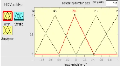
A. Fuzzy Logic Membership Functions:
The dc-dc converter is a nonlinear function of the duty cycle because of the small signal model and its control method was applied to the control of boost converters. Fuzzy controllers do not require an exact mathematical model. Instead, they are designed based on general knowledge of the plant. Fuzzy controllers are designed to adapt to varying operating points. Fuzzy Logic Controller is designed to control the output of boost dc-dc converter using Mamdani style fuzzy inference system. Two input variables, error (e) and change of error (de) are used in this fuzzy logic system. The single output variable (u) is duty cycle of PWM output.
The Membership Function plots of error
. The Membership Function plots of change error
the Membership Function plots of duty ratio
B. Fuzzy Logic Rules:
The objective of this dissertation is to control the output voltage of the boost converter. The error and change of error of the output voltage will be the inputs of fuzzy logic controller. These 2 inputs are divided into five groups; NB: Negative Big, NS: Negative Small, ZO: Zero Area, PS: Positive small and PB: Positive Big and its parameter [10]. These fuzzy control rules for error and change of error can be referred in the table that is shown in Table II as per below:
Table II
Table rules for error and change of error
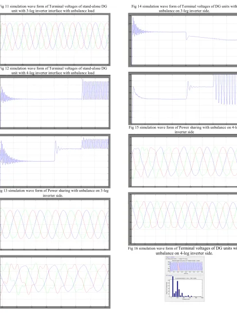
V. SIMULATION RESULTS
Fig 11 simulation wave form of Terminal voltages of stand-alone DG unit with 3-leg inverter interface with unbalance load
Fig 12 simulation wave form of Terminal voltages of stand-alone DG unit with 4-leg inverter interface with unbalance load
Fig 13 simulation wave form of Power sharing with unbalance on 3-leg inverter side.
Fig 14 simulation wave form of Terminal voltages of DG units with unbalance on 3-leg inverter side.
Fig 15 simulation wave form of Power sharing with unbalance on 4-leg inverter side
Fig 17 THD analysis of voltage and current in 3-leg and 4-leg inverter operation with fuzzy logic
VI. CONCLUSION
This paper presents a novel method to improve the power quality at point of common coupling for a3-phase 4-wire DG system using PI controller and fuzzy logic controller for grid interfacing inverter. The gridinterfacing inverter is effectively utilized for power conditioning. This approach eliminates the additional powerconditioning equipment to improve power quality at PCC. The grid interfacing inverter with the proposedapproach can be utilized to inject real power generation from RES to the grid, and operate as a shunt ActivePower Filter (APF). The current unbalance, current harmonics and load reactive power, due to unbalanced andnon-linear load connected to the PCC, are compensated effectively such that the grid side currents are alwaysmaintained as balanced and sinusoidal at unity power factor. Moreover, the load neutral current is preventedfrom flowing into the grid side by compensating it locally from the fourth leg of inverter. When the powergenerated from RES is more than the total load power demand, the grid-interfacing inverter with the proposedcontrol approach not only fulfils the total load active and reactive power demand (with harmonic compensation)but also delivers the excess generated sinusoidal active power to the grid at unity power factor. The settling of the system is improved hence proposed fuzzy logic controller hasfast response, high accuracy of tracking the DC-voltage reference, and strong robustness to load suddenvariations.
REFERENCES
[1] M. Dai, M. N. Marwali, and A. Keyhani, “A three-phase four wireinverter control technique for a single distributed generation unit inisland mode,” IEEE Transactions on Power Electronics, vol. 23, no. 1,pp. 322–330, 2008.
[2] S. El-Barbari and W. Hofmann, “Digital control of a four leg inverter forstandalone photovoltaic systems with unbalanced load,” inTwenty-sixthAnnual conference of IEEE, IECON, (Nagoya, Japan), pp. 729–734,October 2000.
[3] X. Song, Y. Wang, W. Hu, and Z. Wang, “Three reference framecontrol scheme of 4-wire grid-connected inverter for microgrid underunbalanced grid voltage conditions,” inTwenty-Fourth Annual IEEEApplied Power Electronics Conference and Exposition, (Washington,USA), pp. 1301–1305, February 2009. [4] M. N. Marwali and A. Keyhani, “Control of distributed generationsystems - Part I : voltages and currents control,” IEEE
Transactionson Power Electronics, vol. 19, no. 6, pp. 1541– 1550, 2004.
[5] M. N. Marwali and A. Keyhani, “Control of distributed generationsystems - Part II : load sharing control,”IEEE Transactions on PowerElectronics, vol. 19, no. 6, pp. 1551– 1561, 2004.
[6] I. Vechiu, H. Camblong, G. Tapia, B. Dakyo, and O. Curea, “Control offour leg inverter for hybrid power system applications with unbalancedload,” Energy Conversion and Management, vol. 48, no. 7, pp. 2119–2128, 2007.
[7] I. Vechiu, O. Curea, and H. Camblong, “Transient operation of a fourleg inverter for autonomous applications with unbalanced load,” IEEETransactions on Power Electronics, vol. 25, pp. 399–407, February2010.
[8] R. Zhang, V. H. Prasad, D. Boroyevich, and F. C. Lee, “Threedimensional space vector modulation for four-leg voltage-source converters,” IEEE Transactions on Power Electronics, vol. 17, no. 3,pp. 314–326, 2002.
[9] R. R. Sawant and M. C. Chandorkar, “A multifunctional four-leg gridconnected compensator,”IEEE Transactions on Industry Applications,vol. 45, no. 1, pp. 249–259, 2009. [10] A. Kouzou, H. A. Rub, M. O. Mahmoudi, M. S. Boucherit, andR. Knennel, “Four wire shunt active filter based on four-leg inverter,”in International Aegean Conference on Electric Machines and PowerElectronics &Electro motion, (Istanbul, Turkey), pp. 508–513, September 2011.
[11] D. Vyawahare and M. C. Chandorkar, “Power flow analysis in standalone 4-wire, 4-leg inverter microgrid with unbalanced loads,” inSixteenth European Conference on Power Electronics and ApplicationsEPE-ECCE, (Lappeenranta, Finland), pp. 1–10, August 2014.
[12] D. Vyawahare and M. C. Chandorkar, “Line interactive distributed 4-leg inverter system with unbalanced and nonlinear loads,” in IEEEInternational Conference on Power Electronics, Drives and EnergySystems (PEDES), (Mumbai, India), pp. 1–6, December 2014.
[13] M. P. Kazmierkowski, R. Krishnan, and F. Blaabjerg,Control in PowerElectronics: Selected Problems. USA: Academic Press, 2002.
[14] M. J. Ryan, R. D. Lorenz, and R. W. D. Doncker, “Modeling of multilegsine wave inverters: A geometric approach,” IEEE Transactions onIndustrial Electronics, vol. 46, no. 6, pp. 1183–1190, 1999.