SECOND ORDER AC-DC LOAD FLOW AND
STATE ESTIMATION PROBLEM
VICTORIA Z
UNIVERSITY
z o o o
-<
A thesis submitted in fulfilment of the requirements for the degree of
DOCTOR Q OSOPHY
Md. Zahidul Haque
B.Sc, M.Sc. Engg. (Electrical & Electronic)
in the
Department of Electrical and Electronic Engineering Faculty of Engineering
Haque, Md. Zahidul
I hereby declare that the following thesis entitled, "A Sequential
Approach of Solving Second Order AC-DC Load Flow and State Estimation Problem", which is being submitted by myself, in fiilfilment of
the requirements for the award of the Degree of Doctor of Philosophy in Electrical and Electroruc Engineering, Victoria University of Technology, Australia. The matter embodied in this thesis has not been submitted in part or full to any other University or Institute for award of any degree.
Acknowledgements
The author wishes to express his heartfelt gratitude and sincere thanks to his principal supervisor. Dr. A. Kalam, Associate Professor of the Department of Electrical and Electroruc Engineering, Victoria University of Technology, Australia, for his kind guidance, invaluable support, constant encouragement and supervision throughout the course of this research.
The author would like to express his gratitude to his co-supervisor Dr. Qin Jiang for her support during this research.
The author is profoundly grateful to Associate Professor Wally Evans, Head of the Department of Electrical and Electroruc Engineering for providing me with the necessary facilities in order to successfully complete this research.
The author would like to express his sincere gratitude to Mr. Richard Jacewicz, System Support Engineer, the Department of Computer and Mathematical Science, VUT for his help and kind permission for the use of Cyber where some computations were performed.
The author is thankful to the people who have helped him directly or indirectly during the course of study.
also grateful to his daughter Zakia Haque and son Shafiul Haque for the time they had to miss their father.
Contents
Declaration i
Acknow^ledgements ii
Contents iv
List of Tables x
List of Figures xv
Nomenclature xvii
Abstract xxii
Preface xxiv
CHAPTER 1: INTRODUCTION AND REVIEW
1.1 Introduction 1 l.I.l AC-DC power system load flow 2
1.2 Review of ac-dc load flow 3 1.2.1 Gauss-Seidel method 5 1.2.2 Newton-Raphson method 6 1.2.3 Advantages of NR method over GS
method 7 1.2.4 Fast decoupled method 8
1.2.5 Advantages of FD method over NR
method 9 1.2.6 Limitations of NR and FD methods 10
1.3.2 Characteristics of the proposed methods in
comparison with FDLF method 15 1.4 AC-DC power system state estimation 16
1.4.1 Definition 16 1.4.2 Review of ac-dc state estimation 16
1.4.3 Limitations of WLS and FD estimators and
scope of further investigation 20 1.4.4 Characteristics of the proposed method 21
1.5 Scope and objective 22 1.6 Originality of the thesis 23 1.7 Development of thesis 24
PART - 1 Load Flow
CHAPTER 2: INTEGRATED AC-DC LOAD FLOW IN RECTANGULAR CO-ORDINATES
2.1 Introduction 29 2.2 Development of mathematical model 30
2.2.1 DC converter model 30 2.2.2 Mathematical model for rectangular
co-ordinates 32 2.2.3 AC network model 37
2.3 First order ac-dc load flow method 38
2.3.1 Mathematical model 39
2.3.2 Solution steps 42
CHAPTER 3: SECOND AND DECOUPLED SECOND ORDER AC-DC LOAD FLOW IN
RECTANGULAR CO-ORDINATES
3.1 Introduction 46 3.2 second order ac-dc load flow method 49
3.2.1 Mathematical model 50 3.2.2 Salient featiires of SRLF algorithm 54
3.2.3 Solution steps 55 3.3 Decoupled second order ac-dc load flow
method 57 3.3.1 Mathematical model 59
3.3.2 Distinguishing features of the DSRLF
algorithm 62 3.3.3 Solution steps 63
3.4 Conclusions 65
CHAPTER 4: SIMULATION STUDIES
4.1 Introduction 67 4.2 Parameters selection 68
4.2.1 Initialisation 68 4.3 Modification of standard test systems (load flow) 69
4.4 Ill-conditioned system 71 4.4.1 High values of branch resistance 71
4.4.2 High value of R/X ratio 72
4.5 Loading conditions 73
4.6 Test results 74 4.7 Analysis of simulation results 85
PART - II State Estimation
CHAPTER 5: INTEGRATED AC-DC STATE ESTIMATION IN RECTANGULAR CO-ORDINATES
5.1 Introduction 95 5.2 Mathematical modelling 97
5.2.1 AC system measurements 98 5.2.2 DC system measurements 98 5.2.3 Interface system measurements 98 5.3 Basic formulation .". 98
5.3.1 Formulation of h(x) 100 5.4 First order ac-dc state estimator 104
5.4.1 Solution steps 105 5.4.2 Characteristics of H and G matrices 107
5.4 Conclusions 107
CHAPTER 6: SECOND AND DECOUPLED SECOND ORDER AC-DC STATE ESTIMATOR IN RECTANGULAR CO-ORDINATES
6.1 tiitroduction 109 6.2 Second order ac-dc state estimator 110
6.2.1 Algorithmic development 113 6.2.2 Characteristics of SRSE 116
6.2.3 Solution steps 117 6.3 Decoupled second order ac-dc state estimator 117
6.3.1 Algorithmic development 119
6.3.2 Advantages 125 6.3.3 Characteristics of DSRSE 125
6.4 Conclusions 129
CHAPTER 7: SIMULATION STUDIES
7.1 Introduction 130 7.2 Initialisation 131 7.3 Modification of standard test system (state
estimation) 132 7.4 Performance indices 133
7.5 State estimation under ill-conditioned system 134 7.6 State setimation in case of missing data 135 7.7 State estimation imder abnormal reference
voltage 136 7.8 Test results 136 7.9 Analysis of simulation results 177
7.10 Conclusions 186
PART - III General Conclusions
CHAPTER 8: GENERAL CONCLUSION AND
SUGGESTIONS FOR FUTURE WORK
8.1 Conclusions 188 8.2 Futiirework 195
REFERENCES 197
APPENDICES
Appendix - A : Per-mut system 208 Appendix - B : First and second order derivatives 209
and basic mathematical model for ac system 217
Appendix - D : System data 234 Appendix - E : Bus diagram and dc link, mesh, mesh-link
configuration 270 Appendix - F : Load flow and line flow solutions of different
4.1 Effect of control specifications on convergence and solution
time for 14 bus system with dc link 75 4.2 Effect of control specifications on convergence and solution
time for 14 bus system with dc mesh 75 4.3 Effect of control specifications on convergence and solution
time for 30 bus system with dc link 76 4.4 Effect of control specifications on convergence and solution
time for 30 bus system with dc mesh 76 4.5 Effect of control specifications on convergence and solution
time for 57 bus system with dc link 77 4.6 Effect of control specifications on convergence and solution
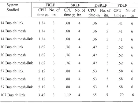
time for 5 7 bus system with dc mesh 77 4.7 Number of iterations and solution time comparison of
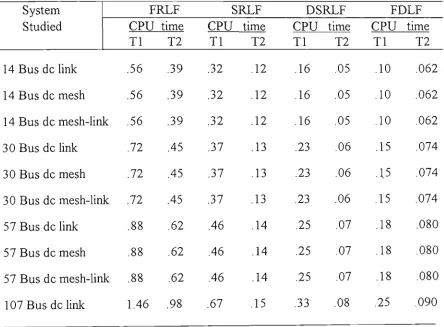
different methods 78 4.8 Percentage of solution time comparison of different
method at different iterative stage 79 4.9 Effect of increasing R on convergence 80 4.10 Effect on convergence of increasing R/X ratio 81
4.11 Effect of convergence for high value of reactive power
loading 82 4.12 Effect of convergence under different loading condition 83
4.13 Effect on convergence for different R/X ratios mider
different loading conditions 84 7.1 Jacobian matrix [H] of a 3 busbar ac-dc system 137
7.2 Gain mati-ix [G] = [H] ^ [W][H] of a tiiree busbar ac-dc
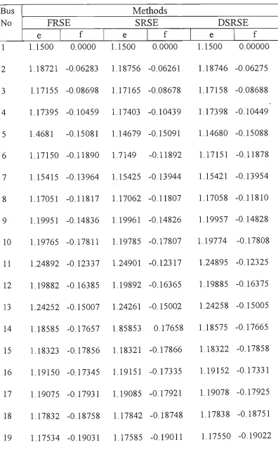
7.3 State estimation results of 14 bus ac-dc link system 143 7.4 State estimation results of 30 bus ac-dc link system 145 7.5 State estimation results of 57 bus ac-dc link system 147 7.6 State estimation results of 107 bus ac-dc link system 148 7.7 State estimation results of 14 bus ac-dc mesh system 149 7.8 State estimation results of 3 0 bus ac-dc mesh system 151 7.9 State estimation results of 57 bus ac-dc mesh system 154 7.10 True values, estimated values and percentage of error of
14 busbar system using DSRSE 156 7.11 True values, estimated values and percentage of error of
14 busbar ac-dc mesh system using DSRSE 157 7.12 True values, estimated values and percentage of error of
30 busbar ac-dc link system using DSRSE 158 7.13 True values, estimated values and percentage of error of
57 busbar ac-dc link system using DSRSE 160 7.14 Maximum and average percentage of error compared
to true values 161 7.15 Computing time comparison of different methods 162
7.16 Percentage of saving in solution time with FRSE
method as reference 162 7.17 Comparison of performance indices 163
7.18 Comparison of performance indices using DSRSE method 163 7.19 Missing data of 5 nodes, namely 2, 3, 4, 5, 6 for 14 bus dc
link 164 7.20 Missing data of 5 nodes, namely 1, 4, 9, 12, 19 for 30 bus
delink 165 7.21 State estimation solution of 14 bus ac-dc mesh system under
abnormal reference voltage (1.15) 169 7.23 Power flow accuracy comparison of 30 bus ac-dc system
under abnormal reference voltage (0.85) 171 7.24 Power flow accm-acy comparison of 30 bus ac-dc system
under abnormal reference voltage (1.15) 173 7.25 Effect of increasing R/X ratio on convergence 175 7.26 Effect of convergence tmder different loading condition 176
D. 1 System data for 14 bus system 234
D.1.1 Bus data 234 D.1.2 Lmedata 235 D.13 Transformer data 236
D. 1.4 Shunt capacitance data 236
D.1.5 DC Imk system 236
D. 1.5.1 Bus data 236 D.1.5.2 Lmedata 236 D.I.6 DC mesh system 237
D. 1.6.1 Bus data 237 D. 1.6.2 Lmedata 237 D.1.7 DC mesh-link system 238
D.1.7.1 Bus data 238 D.1.7.2 Line data 238 D.2 System data for 30 bus system 239
D.2.1 Bus data 239 D.2.2 Line data 240 D.2.3 Transformer data 242
D.2.4 Shunt capacitance data 242
D.2.5 DC link system 243
D.2.6 DC mesh system 243
D.2.6.1 Bus data 243 D.2.6.2 Line data 244 D.2.7 DC mesh-lmk system 244
D.2.7.1 Bus data 244 D.2.7.2 Lme data 244 D.3 System data for 57 bus system 245
D.3.1 Bus data 245 D.3.2 Line data 248 D.3.3 Transformer data 251
D.3.4 Shunt capacitance data 252
D.3.5 DC Imk system 252
D.3.5.1 Bus data 252 D.3.5.2 Line data 252 D.3.6 DC mesh system 253
D.3.6.1 Bus data 253 D.3.6.2 Line data 253 D.3.7 DC mesh-lmk system 254
D.3.7.1 Bus data 254 D.3.7.2 Line data 254 D.4 System data for 107 bus system 255
D.4.1 Bus data 255 D.4.2 Line data 260 D.4.3 Transformer data 267
D.4.4 DC link system 268
D.4.4.1 Bus data 268 D.4.4.2 Line data 269 F. 1 Load flow solution of 14 bus system with dc Imk 280
F.3 Load flow solution of 57 bus system with dc link 283 F.4 load flow solution of 107 bus system with dc link 284 F.5 Load flow solution of 14 bus system with dc mesh 286 F.6 Load flow solution of 30 bus system with dc mesh 288 F.7 Load flow solution of 57 bus system with dc mesh 290 F. 8 Load flow solution of 14 bus system with dc mesh-link 291 F.9 load flow solution of 30 bus system with dc mesh-link 293 F.IO Load flow solution of 57 bus system with dc mesh-link 296
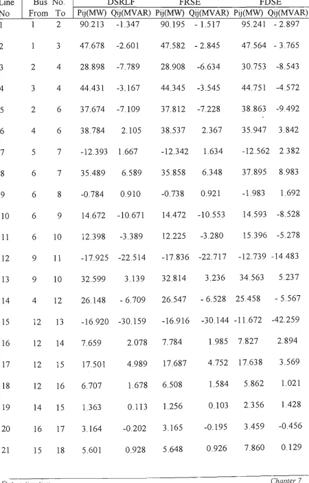
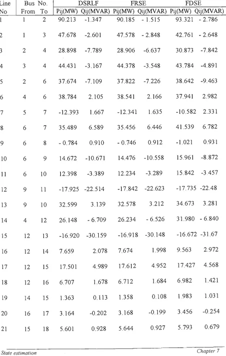
F. 11 Line flow of 14 bus system with dc link 297 F. 12 Line flow of 30 bus system with dc link 298 F.13 Line flow of 57 bus system with dc link 300 F.14 Line flow of 107 bus system with dc link 303 F. 15 Line flow of 14 bus system with dc mesh 304 F.16 Line flow of 30 bus system with dc mesh 305 F. 17 Line flow solution of 57 bus system with dc mesh 307
List of Figures
2.1 HVDC converter model 31 2.2 Thevenin' s equivalent of the HVDC model 31
2.3 Flow chart for FRLF 44 3.1 Flow chart for SRLF 58 3.2 Flow chart for DSRLF 66
4.1 Convergence characteristics of 14 bus system with dc
link .". 89 4.2 Convergence characteristics of 14 bus system with dc
mesh 89 4.3 Convergence characteristics of 14 bus system with dc
mesh-link 90 4.4 Convergence characteristics of 30 bus system with dc
Imk 90 4.5 Convergence characteristics of 30 bus system with dc
mesh 91 4.6 Convergence characteristics of 30 bus system with dc
mesh-link 91 4.7 Convergence characteristics of 57 bus system with dc
mesh 92 4.8 Convergence characteristics of 107 bus system with dc
link 92 5.1 Flow chart for FRSE metiiod 106
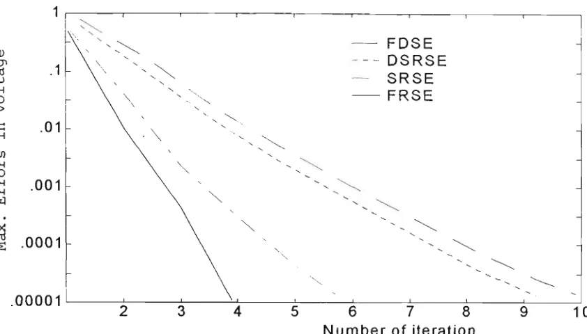
6.1 Flow chart for SRSE metiiod 118 6.2 Flow chart for DSRSE method 128 7.1 Convergence characteristics of 14 bus system with dc
link 179
mesh 179 7.3 Convergence characteristics of 14 bus system with dc
mesh-link 180 7.4 Convergence characteristics of 30 bus system with dc
Imk 180 7.5 Convergence characteristics of 30 bus system with dc
mesh 181 7.6 Convergence characteristics of 30 bus system with dc
mesh-link 181 7.7 Convergence characteristics of 30 bus system with dc
link 182 7.8 Convergence characteristics of 57 bus system with dc
mesh 182 7.9 Convergence characteristics of 57 bus system with dc
mesh-link 183 E.l IEEE 14 bus system 270
E.1.1 14 bus dc link system 271 E.1.2 14 bus dc mesh system 271 E.I.I 14 bus dc link-mesh system 272
E.2 IEEE 30 bus system 273 E.2.1 30 bus dc Imk system 274 E.2.2 30 bus dc mesh system 274 E.2.1 30 bus dc link-mesh system 275
Nomenclature
A'^^^ = Number ofac busbars
N j^ = Number of dc busbars
NL = Number of lines in ac networks
NDL = Number of lines in dc networks
X = State vector
X = Estimated value of state vector
k = Measurement errors or noise
fj. = Overlap angle
R = Residuals
L = Second order term
Z = Measurement vector
J = Jacobian matrix
n = Number of state variables
m = Number of measurements
e p = Real ac busbar voltage at busbar 'p' (pu)
fp = Imaginary ac busbar voltage at buabar 'p' (pu)
Gp^ "^ P^q element of ac network admittance matrix (pu)
Bp^ ^ P.q element of ac network susceptance matrix (pu)
Pp = Real ac power injection at busbar ' p ' (pu)
Qp = Reactive ac power injection at busbar 'p' (pu)
A P^ = Mismatch function of real power at busbar 'p' (pu)
^ Qp = Mismatch function of reactive power at busbar 'p' (pu)
P.J = Real ac power flow in line i,j (pu)
A P.J = Mismatch function of real power flow in line i,j (pu)
^ Qij = Mismatch fimction of reactive power flow in line i,j (pu)
/S.R = Residual for dc network and interface
AIFI = Error in nodal voltage
Vd^ = Dkect voltage at busbar ' i ' (pu)
Id. = Direct current injection at dc busbar ' i ' (pu)
a. = Off-nominal converter transformer tap position for
transformer connected to converter at dc busbar ' i '
C^ = Real part of ac current on the secondary side of converter
transformer at dc busbar ' i ' (pu)
<i, = Imaginary part of ac current on the secondary side of
converter transformer at dc busbar ' i ' (pu) /9. = a , = Igiution delay angle of the rectifier
=/ . = Extinction advance angle of the inverter
Rj^ = DC resistance
Gdc^. = i j t h element of the dc network conductance matrix (pu)
Pd. = DC power injected at dc busbar 'i' (pu)
Pd. = DC power flow in line connecting dc busbars 'i' & 'j'(pu)
Xc. = Commutating reactance of converter at dc busbar 'i' (pu)
^, = Power factor angle at converter at dc busbar 'i'
_3VI
k,
n
3
k,
K
+1, for rectifier connected to ac busbar 'p' and dc busbar
'i'
= -1, for mverter connected to ac busbar 'p' and dc busbar
E{w^) [W]
cil
H(x)
H{xyWH{x) AZ
X
CO
P
T
AC CPU DC DSRLF
DSO DSRSE
= 0, for ac busbar 'p' with no converter connected to it = +1, for ac busbar 'p' with converter connected to it = Covariance matrix of v
-- Weighting matrix
- Weighting matrix inverse
'- Variance of ifh measurements
-- Jacobian matrix
'- Information matrix
'• Mismatch vector
-• Resistance multiplication factor
Value of R/X ratio
Reactive load multiplication factor Real power multiplication factor
Reactive power multiplication factor Specified tolerance
Fail to converge Alternating current Centtal processing uiut Direct current
Decoupled second order rectangular co-ordinate ac-dc load flow
Decoupled second order
ESQ FD FDLF FDSE FO FRLF FRSE GS HVDC LFC NR NRLF PU SO SRLF SRSE WLS WLSE
Exact second order Fast decoupled
Fast decoupled ac-dc load flow Fast decoupled ac-dc state estimator First order
First order rectangular co-ordinate ac-dc load flow First order rectangular co-ordinate ac-dc state estimator Gauss-Seidel
High voltage direct current Load fi-equency control Newton-Raphson
Newton-Raphson load flow Per unit
Second order
Second order rectangular co-ordinate ac-dc load flow Second order rectangular co-ordinate ac-dc state estimator Weighted least square
Weighted least square state estimator
Subscripts
ij,p,q ij.pq p
q d b E M
= Busbar index
= Line connection busbars, i and j or p and q = Real power index
= Reactive power index = DC quantities index = base value
av max
Superscripts
m k
"^^
T t sp min 0 *
= Average value = Maximum value
= Measm^ement variables = Iteration count
= Estimated quantity
= Transpose of a matrix or vector = True values
Abstract
remain constant in the recursive process. The nonluierarity of the network equations is retained. This contrasts sharply to the existing ac-dc load flow and state estimation algorithms which are based on the linearised relationship between the residual and error vectors. Digital solution studies indicate that the SRLF and SRSE are respectively superior to the NR and WLS methods.
Preface
This thesis contains three new mathematical models for ac-dc load flow and state estimation. The algorithms were tested under various operating conditions. Digital simulation results indicate that the proposed methods are superior than the conventional ac-dc load flow and state estimation method. A listing of all the relevant publications related to this thesis are provided below.
[1] M.Z. Haque & A. Kalam, " A comparative study of AC-DC load flow
with the development of new algorithm" International Conference on
Modelling and Simulation, Vol.1, July 12-14,1993, pp. 356-374.
[2] M.Z. Haque & A. Kalam, "Second order dynamic state estimation
using cartesian co-ordinate algorithm". International Conference on
Modelling and Simulation,Vol. 2, July 12-14,1993, pp-707-716.
[3] A.Kalam & M.Z. Haque, "A new version of exact decoupled second
order AC-DC load flow solution in rectangular co-ordinates", lEE
APSCOM-93, Hong Kong, Vol.1, Dec. 1993, pp. 262-267.
[4] M.Z. Haque & A. Kalam, ''"'Exact decoupled second order AC-DC
load solution under loading and ill-conditioned networks",
AUPEC'94, Adelaide, Vol. 3, Sept. 1994, pp. 603-608.
[5] M.Z. Haque & A.Kalam, 'A new method of solving AC-DC power
system state estimation problem" ICEE '96, Beijmg, China, Vol. 2,
Aug. 12-15, pp. 983-987.
[6] A. Kalam, M.Z. Haque & J. Nanda," An exact second order load flow
solution under loading and ill-conditioned networks", Intternational
[7] M.Z. Haque & A.Kalam, 'A comparative study of first and second
order AC-DC state estimator" UPEC '96, Greece, Vol. 2, Sept.
18-20, pp. 578-581.
[8] M.Z. Haque & A.Kalam, "Exact decoupled Second order AC-DC
power system state estimator" 11 CEPSI '96, Malaysia, Vol. 3, Oct.
21-25, pp. 134-143.
[9] M.Z. Haque & A.Kalam, ''Novel decouple AC-DC state estimator"
AUPEC '96, Melbourne, Vol. 3, Oct. 2-4, pp. 599-604.
[10] M.Z. Haque, A. Kalam & L. Roy ," Second order ac-dc power system
state estimator". International Journal of Power and Energy
INTRODUCTION AND REVIEW
1.1 INTRODUCTION
In the modem age of science and technology, the necessity of electricity is increaskig day by day. In view of rapid growth in demand and supply of electricity, electric power system is becoming increasingly large and more complex. Moreover, regular electric supply is the sheer necessity for growing industry and other fields of life. The power industry planners are demanding stronger trend towards supplying electric power of higher quality by improving the system security and its impact on environment in parallel with pursuit of economy. In real life situation, the criterion of perfection is never met, because there are deviations between the model and reality. Load flow and state estimation analysis are an important tool for stable operation and control of power system as well as future planning of power systems. High voltage ac-dc technology has made considerable advances in recent years. Engineers are now considering dc multi-terminal network as a feasible option. Therefore, the load flow and state estimation techniques have to be extended to deal with such mixed ac-dc systems. Multi-terminal dc network integrated into an existing system can improve ac equipment loading and stability, participate hi load frequency control (LFC) and voltage
contribute to the economy of electric power transmission. Multi-terminal dc network as well as two-terminal dc Imks require communication between converter termuials and control of dc system start-up and shutdovm, for coordination of operatmg set points, and for dc system structure changes such as line or terminal outages. Lmk or meshed dc multi-terminal network mtegrated to ac systems is feasible and can be advantageous in certain applications such as bulk power transmission, ac networks intercoimection and reinforcing ac networks.
1.1.1 A C - D C Power System Load Flow
Under normal operating conditions electric transmission systems operate in their steady-state mode and the basic calculations required to determine the characteristics of this state are termed as load flow or power flow [95]. The main objective of load flow calculations is to determine the steady state operating characteristics of the power generation/transmission system for a given set of busbar loads. The load flow calculations provide voltages, power flows and power losses for a specified power system subject to the regulating capabilities of the generators, condensers and on-load tap changing transformers as well as the net power exchange between the individual power system. This information is essential for continuously evaluating the operating performance of a power system and analysing the effectiveness of alternative plans for system expansion to meet the increasing load demand. The load flow studies are also necessary for the power system stability assessment, contingency evaluation and economic operation. The significance of these studies has become more relevant
large size power systems in a real-time environment.
Imposing a dc network between ac generators and load or between two ac systems offer several technical and economical advantages which are described m the next section. The growing nmnber of schemes in existence and under consideration demands corresponding modelling facilities for planning and operational purposes. In recent years, great advantages have been made in converter technology which has resulted in cheaper and more reliable power utilisation. The basic load flow has to be substantially modified to be capable of modelling the operating state of the combined ac and dc systems under the specified conditions of load, generation and dc system control strategies.
1.2 REVIEW O F AC-DC LOAD FLOW
Load flow calculation has a very important role in power system research and power industry. Although many methods have been proposed, further development of load flow method for the purpose of obtaming greater computational speed, lower storage requirements, more reliable and better convergence pattern and especially for loading and ill-conditioned systems, is still a very sigruficant field of study.
The load flow calculation is one of the most commonly used tools in power system engineering. For this reason, the history of load flow calculation is a relatively long one. The initial work of load flow studies has been carried
proposed [1-6]. However, most of these studies have been carried out on ac systems [7], and not much work have been reported on the ac-dc systems. The options of dc lme linking to ac systems are used as they are better technical altemative and are financially beneficial in certaui occasions such as:
• to facilitate the operation of interconnected ac systems at different frequencies;
• to enhance the operation of ac systems with incompatible frequency conttol techniques;
• to ttansmits power in underground and submarine cables; • to ttansfer bulk power over long distances more
economically;
• to reduce the short circuit level in an interconnected ac system;
• to increase the transient stability margin; • to improve dynamic stability.
Earlier digital solution of the power flow in ac-dc systems is the work done by Horigome et al. [17], Gavrilovic et al. [18], Hingorani et al. [19], Barker et al. [20], Brever et al. [21], Sato et al. [22], Sheble et al. [23] and others. Additional characteristics of the cartesian coordinate formulation for ac load flows were investigated by El-Hawary et al. [14], Rao et al. [15], Krishnaparandhama et al. [16] and Cory et al. [89]. However, their works were limited upto the first order derivatives of the
1.2.1 Gauss-Seidel Method
The Gauss-Seidel (GS) method is an iterative algorithm for solving a set of non-linear algebraic equations. In this method the solution vector is assumed, based on guidance from practical experience in a physical situation. One of the equations is then used to obtain the revised value of a particular variable by substituting in it the present value of the remaining variables. The solution vector is immediately updated in respect of this variable. The process is then repeated for all the variables thereby
completing one iteration. The iterative process is then repeated till the solution vector converges within prescribed accuracy.
The initial effort in the digital solution of the load flows was based on the GS method. The method was extensively used by Ward et al. [1], Laughton [94], Clan- et al. [2], Glimn et al. [5] and many others. Therefore, the initial algorithms developed for ac-dc load flow problems were also based on the GS technique in the sequential framework [17-22]. In the sequential approach, dc parameters are estimated first and then holding these parameters constant, ac parameters are solved. Next, the ac parameters are used to readjust the dc parameters. The process is continued until a solution with the specified accuracy is obtamed. An extensive uivestigation indicated that solvmg the dc link at every GS iteration increases the total computing time. However, this feature was absent m other methods [22]. It was also observed that there is no need to have the full
convergence scheme needs less overall solution tune. The chief advantage of the GS method is the case of programming and most utalisation of core memory. Also the GS method performs satisfactorily on small and well conditioned networks. However, on some large systems it encounters convergence problems. Further evidence is the fairly well known fact that the convergence of the GS method is poor for system having lines with large R/X ratios.
1.2.2 Newton-Raphson Method
Newton-Raphson (NR) method is an iterative solution algorithm for solving a set of simultaneous non-linear equations in an equal number of unknovms. At each iteration the non-luiear problem is approximated by the linear matrix equation. The linearising approximation can be visualised in the case of a single-variable problem. The NR algorithm will converge quadratically if the fimctions have continuous first derivatives in the neighbourhood of the solution. The Jacobian matrix is non-singular, and the initial approxi-mations of the state vectors are close to the actual solutions. The method is sensitive to the behaviour of the functions i.e. the more linear they are, the more rapidly and reliably the method converges.
The NR method along with its companion techniques of sparsity and optimal ordering is successful in the ac load flow [8,9]. Stott [87] combined the dc link solution techruque of Sato et al. [22] with the NR ac load flow programme and solved the ac-dc load flow problem in the sequential framework. The method works quite well for most of the system. The NR method, though accm^ate and reliable for most of the
this approach :
• the convergence characteristics are quadratic in nature;
• speed advantage of the NR method in solving the ac part of the system - particularly for large systems is not fully realised;
• link calculation is time consuming and " involves complex logic;
• the algorithm is relatively mflexible for adopting conttol specifications;
• convergence is of arbittary nature and not fully reliable;
• the method does not perform well under ill-conditioned situation.
The problems outlined above were mitigated by combining the ac load flow and dc link solution in an integrated NR solution process [24,27,87]. Some modified version of ac-dc load flow methods have been proposed [31-33,44,48,86]. This approach was clakned to be faster and more stable than the sequential one using the NR techiuque.
1.2.3 Advantages Of N R Method O v e r G S Method
The rate of convergence of GS method is slow, requiring a considerably greater number of iterations to obtain a solution, particularly for large
ordered triangular factorisation, the NR method for solving load flow has become faster than GS method and the number of iterations is vutually independent of system size due to the quadratic characteristic of convergence. One NR iteration is equivalent to about seven GS iterations [95]. For a 500 bus system, the conventional GS method takes about 500 iteration and the speed advantage of the NR method is about 15:1 [95]. The time per iteration in both these methods increases almost directly as the nmnber of buses of the network. In the GS method the convergence is affected by choice of slack bus and the presence of series capacitors. On the other hand, the NR method is very reliable in system solving, given good starting approximations. The method is readily extended to include tap-changing ttansformers, variable constants on bus voltages, and reactive and optunal power schedulmg. Therefore, for small and large systems the NR method is faster, more accurate and more reliable.
1.2.4 Fast Decoupled Method
The fast decoupled (FD) load flow method is actually an extension of NR formulated ui the polar coordinates with certain approximations. These approxunations are assumed to be valid due to the fact that any practical electtic power ttansmission system operation in the steady-state condition has sttong mterdependence between active powers (P) and voltage angles
{S), and between reactive powers (Q) and voltage magnitudes (V). So, the
coupling between tiie ?-S and Q-V components of tiie problem is relatively weak. The Jacobians of tiie decoupled Newton load flow can be made constant. This means that they need to be triangularised only once per iterative solution.
by mmrnial computing tune and computer memory reqmrements. The FD method developed by inttoducing few approximations into the NR model, though generally is very efficient, is knovm to have the disadvantage of poor convergence characteristic for systems having lines with large R/X ratios. The FD method was extended to the ac-dc load flow by Arrillaga
et al. [25], Reeve et al [28], Arrillaga et al. [26,39] El-Marsafawy et al
[29], Fudeh e? a/. [30], De Silva e/a/. [91] and many otiiers. A large number of algorithms with varying degree of sophistication and versatility are available ui the literature for the ac-dc load flow usmg the FD techiuque. Among tiiem, the algorithms proposed by Arrillaga
et al [25,26] and El-Marsafawy et al [29] uskig the simultaneous solution
scheme are computationally superior, particularly viable and technically versatile.
1.2.5 Advantages Of F D Method O v e r N R Method
In case of FD method the convergence characteristics is geometric in nature, whereas in NR method the convergence characteristics is quadratic. Though FD method requires five-six iterations to obtain required convergence but the total solution time is far better than NR method. The speed per iteration of the FD method is about five times than that of formal NR method and the storage requirements are about 60 percent of the formal NR method [95]. The FD load flow can be used in optimisation studies for a network and is particularly useful for accurate information of both real and reactive power
for multiple load flow studies, as in contingency evaluation for system security assessment.
1.2.6 Limitations Of N R and F D Methods
An inspection of the available literature indicates that practically adopted ac-dc load flow algorithms are based on either the NR technique or the FD technique. These algorithms are reported to be successfiil. However, they have got some lunitations. Some investigators [35-40] have shovm that the NR techiuque encoimters convergence problem on the ill-conditioned networks. On the other hand, the FD technique does not perform well if the decoupling assumptions are not valid. It also has the disadvantage of poor convergence characteristic for the systems having lines with large R/X ratios.
It can be noted from the above that the NR method requires large computing time and encounters convergence problems for the ill-conditioned systems [36]. Mention has also been made [34-38] that the FD technique does not perform well for all the systems and under all the operating modes, the lunitations of the FD load flow method are:
• slow or oscillatory convergence is encountered at buses connected to branches with R/X ratios exceed from unity or higher values;
convergence rate of PS and Q-V decoupled algorithms are determined by how well the coefficient mattices approximate to the slope of the function ^?/^5 and
dClldV, respectively. These approxunations are excellent
around ^ = 0 and V = 1 pu. At high system active or reactive power loadings (large S 's and poor Vs) the approximations deteriorate;
• the rate of convergence are sttongly mfluenced by the couplmg between P-^ and Q-V matiiematical models. This coupling decreases with system loadmg levels and branches R/X ratios and consequently the convergence rate decreases;
• on the ill-conditioned power systems the method often encounters oscillatory convergence;
• also on loading conditioned system the method some times take long time to converge;
• the method also fails with most of the load flow equivalencing techniques, due to the large value of shunt and series admittances contributed by an equivalent of the extemal parts of the inter-connected power system.
Ghonem et al. [90] proposed a new version of the decoupled load flow method, which is claimed to be superior to the original version of the FD algorithm. However, the method is not examined under ill-conditioned and different loading conditions. Also the method can be applied on ac system only. Nanda et al. [97] proposed a decoupled power flow model with some justifiable network assumptions. The model exhibits stable convergence
behaviour for both well behaved and ill-conditioned situations. However, the algorithm is in polar coordinate formulation and there is no provision for dc networks. Haque [96] developed a decoupled load flow algorithm without ignoring the coupling sub-Jacobians and the method performs well
under ill-conditioned networks. Also the method reduces the computing time as compared to the otiier methods, but his study was confined to ac systems.
1.3 Cartesian Co-ordinate Second Order Method
In this thesis, a second order method was suggested, so as to achieve a more accurate model, by considering the first three terms of the Taylor series expansion of the load flow equations [11,45,47,88]. Iwamato et al. [12] proposed a second order method using rectangular co-ordinate formulation and showed that no terms of the Taylor series expansion need be neglected in this method. From the Iwamato's method it is observed that though the results show considerably reduced computing time as compared to the NR method, it is quite inferior to the FD method from the point of view both memory and time as clearly brought in the discussion of reference 40. Even Roy's [11] method is not superior to FD method on this ground. Rao et al. [40] developed an exact second order load flow model in rectangular co-ordinate and claim to have faster and requiring less computer storage than any other existing second order method. The memory requirement of their method is comparable to that of the FD method and is more reliable than the FD method for ill-conditioned system.
All the above discussions however, are pertinent to ac load flow only. An inspection of the available literature indicates that practically adopted ac-dc load flow algorithms are based on either the NR technique or the FD technique. Some investigations have shown that the NR technique encounters convergence problems on the ill-conditioned networks
[34,36,42,43]. On the other hand, the FD techniques do not perform well if the decouplmg assumption are not valid. Though FD methods have been used for ac-dc system their convergence for different loading condition and ill-conditioned situation have not been examined so far. The usual assumptions and approximations in FD model when applied to ac-dc system may meet convergence problem while dealing with ill-conditioned system, represented by system having lines of large R/X ratios, presence of capacitive series branches etc. In such a situation it may be worthy to use an exact model based on the concept of second order ac-dc system" and then examining in details the performance of this model as compared to that of FD model, not only for well behaved system but also for ill-conditioned system.
Literature survey reveals that till date, second order load flow model for ac-dc system does not exist. The main objective of the present work is to develop a model for ac-dc system based on the concept of second order load flow technique and compare its performance with FD model for different loading condition and ill-conditioned situation. While developing the second order load flow for the ac-dc system attempt has been made to explain the desirable feature of co-efficient matrix which leads to the development of faster version of the model.
1.3.1 Characteristics Of the Second Order and Decoupled Second Order Algorithms
The attractive features of the second order (SO) and decoupled second order (DSO) algorithms are:
ac network equations are completely expressible in the Taylor series involving terms upto the second order only; Jacobian matrix is constant and thereby needs to be computed and triangularised once only in the iterative scheme;
second order derivatives are not required to be stored in the matrix form;
SO method is faster than the NR method and' requires comparable memory;
SO method needs more computmg time and computer storage than the FD method;
DSO method is faster than the NR and SO metiiods and requires less storage;
computational requhements (storage and computing time) of the DSO method are comparable witii those of the FD
method;
SO and DSO metiiods are computationally more stable than the NR and FD methods, as no assumptions or Imearisations have been used in the formulation of these
methods.
1.3.2 Characteristics Of the Proposed Methods in Comparison With F D Method
The characteristics of the proposed methods are ascertamed and compared with those of the FD algorithm. The main observations are summarised below:
• cartesian co-ordinate formulation of the ac-dc load flow problem is feasible;
• omission of some higher order derivatives of the Taylor series associated with dc converter buses and inclusion of the second order derivatives lead to a viable ac-dc load flow solution method;
• solution time of the SO algorithm is less compared to the first order (FO) ac-dc method. However, the storage requhement is similar;
• solution time and computer storage of the DSO ac-dc load flow algorithm are comparable to those of the FD ac-dc method;
• convergence characteristics are moderately influenced by the nature of the conttol specifications; the method performs well on some ill-conditioned networks where the FD method some time fails to converge;
• the proposed methods performs well under different loading condition where the FD method does not perform well;
for some conttol specifications, the proposed methods seem to perform better than the FD ac-dc method.
1.4 Ac-DC
POWER SYSTEM STATE ESTIMATION1.4.1 Definition
State estimation is defined as a statistical procedure for deriving from a set of measurements, a 'best' estimate of the system state. State estimation is a digital processing schedule of scheme which provides a real time data base for many of the centtal and dispatch fimctions in a power system. In the field of power system, the objective is to provide a reliable and consistent data base for security moiutoring, contingency analysis, economic operation and system conttol. The estimator processes Ihe imperfect information available and produces the best estimate of the true state of the system.
1.4.2 Review Of A c - D c State Estimation
The work towards state estimation or real time monitoring of power system started in early seventies. A number of methods are available in the literature for the state estimation of electric power systems. Schweppe
et al. [51] and Dopazo et al. [49] formulated on-lme power system state
estimation algorithms using the weighted least square (WLS) and independent equations. The contribution was supplemented and extended by a number of researchers, including Smith [50], Schweppe et al. [54], Larson et al. [52], and Dopazo et al [53]. Among these solution techiuques, the WLS approach has gained widespread applications in the power industry. The popularity of the WLS method can be attributed to the fact that, it provides a best fit of the complex nodal voltage, gives a set of redundant nodal power injections and line flow measurements while
handling input data errors. A problem associated with this approach is that the statistical characteristic of the errors must be known a priori-to determine the proper values for the weightmg factors. Another numerical difficulty encountered is that, if sufficient redundancy is not included, ill-conditioning of system equations may lead to poor convergence. Further, the computer storage and time requirements are relatively large.
The real time monitoring using independent equations (real time load flow) is based on the node injections as input data, but utilises independent line flows as redundant information for correction of erroneous/missing data. It however, does not make use of the P-Q busbar voltage measurements. Further, it requires a high level of accuracy in the input data to ensure the detection of bad data. The chief merit of this approach is that, unlike the basic WLS method, it does not require a large nmnber of redundant data, thereby, reducing the cost of metering and communication facilities.
To overcome the large computational requirement associated with the basic WLS approach, a number of altemative algorithms [55-58,85] have been suggested. One such modification involves the application of the ?-3 and Q-V decouplmg technique used in the conventional fast decoupled load flow approach [59-63,93]. This algoritiim referred to as the fast decoupled state estunator (FDSE) has been demonsttated to be computationally very efficient, and seems to enjoy wide acceptance. Tripathy et al [84] developed a state estimator algorithm using Newton's method, the algorithm performs well on ill-conditioned networks but it can
only be applied to ac networks. MonticeUi et al [92] proposed a decoupled state estimator witiiout zeromg the couplmg submatiices and the method performs well under ill-conditioned networks but no provision is made for dc system. Habiballah et al [98] proposed a decoupled state estimation algorithm with efficient data stracture management, which substantially reduced the computing time. However, the algoritiim has not been tested under loaded and ill-conditioned network, also theh study was confmed to ac system. Abou El-Ela [99] proposed a state estimation techiuque based on the exact linearisation of the cartesian co-ordinate formulation of nodal load flow equations. The technique reduces the computing time and is also suitable for solving ill-conditioned network which have large bad-data points. However, the algorithm can only be applied on the ac system.
Dopazo et al [53] proposed a method based on the line flow measurements only for the evaluation of the nodal voltages. The technique was shown to be efficient. It has a number of limitations, such as:
• it does not make use of nodal measurements;
• it involves a special type of metering and communication sttategy.
Subsequent developments mvolved extendmg andenlargmg the range of the application of the available techiuques to encompass the bad data [64-68], ttacking [69-72] and dynamic [73-74] aspect of the state estimation. Some mvestigators using linear progranung techruque in order to reduce tiie computmg tune [13,85]. An mteresting comparisons of the state estimation techiuques are available in references 75 and 76 . The
comparison can be usefiil in the selection of a suitable method for a particular power system. It is observed that since early seventies many papers have been published on the state estknation of the power systems [93]. Different types of algorithms - static, ttacking and dynamic have been proposed. These studies, however, were mostly confined to ac system.
Realising the existence of ac-dc electric networks, attempts were made to extend the ac system state estimation algorithms to accommodate dc links and multi-terminal network. Sirisena et al [77] presented an algorithm for the mixed system involving only the dc links. No provision was made for multi-terminal dc networks. Glover et al [78] devised an algorithm for the multi-terminal dc networks and was coirfined to the dc network state estimation. The ac-dc interconnected system (converter system) was not included in the study. Leita da Silva et al. [79] presented a more general state estimator capable of handling dc multi-terminal networks embedded in an ac system. The limitations of the Sirisena et al [77] and Glover et al [78] algorithms were overcome to a great extent. The FD state estimation technique originally applied on the ac systems [58] was extended by Jagatheesan et al. [63] to the ac-dc systems and a sequential scheme was proposed. All these algorithms [56-81] are based on the polar formulation and the fust order derivatives of the Taylor series. Roy et al [41] proposed a second order state estimation by using the conventional load flow equations. The algorithm is not very fast and it can only apply to ac system. The proposed state estimation algorithms is based on the rectangular formulation, and the first and second order derivatives of the Taylor series. The algorithm is capable of
handling the ac system, the dc system and the mterconnection system simultaneously. The ac, dc and converter networks are modelled in the rectangular form. AC-DC performance equations are completely expre-ssible in the Taylor series and terminate after the second order derivatives. However, the interconnection system equations contam terms upto the sixth order derivatives m the Taylor series. The fact that the ac, dc and converter equations are completely expressible in the Taylor series and the Taylor series is exact was hitherto, not reported. The proposed method is more general emd free from many lunitations.
1.4.3 Limitations Of WLS and FD Estimators and Scope Of Further Investigation
Most of the commercial state estimation programmes are based on the FD techruque. However, the success of these programmes are subject to satisfying the underlying assumptions, viz :
• voltage magnitudes are near unity;
• angular differences between the adjacent nodal voltages are small;
• shunt connection to ground is small;
• X/R ratios of the lines are large;
Some investigations revealed that the FD estunator performs satisfactorily so long as the underlying decoupling and associated assumptions are satisfied [56-81]. However, where the assumptions are not valid, convergence problems are encountered and the solution process generally diverges. As such, the FD estimator although simple and efficient is not
versatile. Thus, there exists a need to develop new methods for the state estimation of ac-dc power systems which should possess the desirable features of the FD estunator, but be free from its lunitations. An attempt is made in this thesis to develop and test such methods.
One of the objectives of the thesis is to develop new algorithms for the state estimation of ac-dc power systems, that are both efficient and stable. The algorithms used for the state estimation of ac-dc power systems are based on the polar co-ordinate formulation of the network performance equations. The network equations are expanded in the Taylor series, and the first order derivatives are used in developing the solution model.
Effects of the cartesian co-ordinate formulation of the network performance equations were studied for the state estimation of ac networks [81-83]. Details of the benefits of cartesian co-ordinate formulation for load flow and state estimation are given in Appendix - C. No such attempt seems to have been made for ac-dc systems. As such, the aim of the thesis is to develop new methods for the state estimation of ac-dc systems, that are based on the rectangular co-ordinate formulation of the network equations.
1.4.4 Characteristics Of the Proposed Method
The method is characterised by the following :
• ac system, dc system and ac-dc mterconnection system are modelled separately and mdependently. Essentially, an
integrated ac-dc system is partitioned uito tiiree independent subsystems;
state of three parts is estimated separately. The state estunation problem is split into three number of smaller sub-problems. This mttoduces interface errors;
objective (cost) fimction is broken into three parts. The objective function of each part is minimised mdependently. The cost fimction of the total system is not minimised. The sum of the local miruma need not be the global minimum; • Couphng sub-matrices among the ac system, the dc system
and the intercoimection system are ignored. This inttoduces a major approximation.
1.4 SCOPE AND OBJECTIVE
From the literature servey it is clear that the FD ac-dc method does not appear to be suitable for all kind of power systems under all operating conditions. On the other hand computational requirements of the NR ac-dc method are large. So there is a need for developing new methods for the ac-dc load flow that are devoid of the limitations of the FD and NR methods.
The main objectives of the thesis are:
• to develop a new mathematical model which is more exact and requires smaller time for computation. Hence, the
second order load flow model m rectangular co-ordinates is chosen as the basic tool;
• to develop a matiiematical model which can operate ac system, dc system and the ac-dc (interface) system mdependently;
• to formulate a new model which is highly reliable and provide solutions for a number of ill-conditioned systems; • to apply SO and DSO techniques for solvmg the load flow
and state estimation problems of ac-dc power systems.
1.6 ORIGINALITY O F THE THESIS
The work presented in this thesis is based on the presentation of the ac-dc network equations in the cartesian co-ordinate form for the solution of the load flow and state estimation problems. The option of dc link on ac system has got some advantages. The power system engineers are more concemed about dc system. Though many paper has been published in order to solve the ac-dc load flow and state estimation problems but new ones high lights more reliable and atttactive features. Literature survey reveals that till date algorithms for second order ac-dc load flow and state estimation does not exist. The original conttibutions of this thesis are summarised as follows:
1. A mathematical model has been developed for ac-dc load flow and state estimator based on the concept of second order techiuque.
2. A new mathematical model of decoupled second order ac-dc load flow and state estimator has been investigated without
ignoring the coupling sub-Jacobians. As there are no major approximation on the model, the solutions are more accurate and reliable.
3. The proposed algorithms have an interesting aspect that, the ac and dc part of the networks can be handled separately without modification to the program.
4. The proposed algorithms perform well under different converter conttol specifications and under various operating modes.
5. The performance characteristic of the proposed algorithms are comparable to the NR load flow & state estunation and FD load flow & state estimation and it appears that the proposed algorithms are far superior than the conventional load flow and state estimation algorithms.
6. The proposed algorithms can faithfiiUy be applied to the low voltage distribution system where the line resistance, R or R/X ratios are very high.
7. The proposed algorithms have been tested under different loading conditions and abnormal reference voltages and it performs well.
1.7 DEVELOPMENT O F THESIS
The development of the subject matter of the investigation reported
in the thesis is on the following lines :
Chapter 1 : The fust chapter inttoduces the problem of ac-dc load flow and state estunation. The ac-dc load flow and state estimation are briefly
reviewed. The limitations of the popular methods are described and the scope of further investigations outlined.
Chapter 2 : The ac-dc load flow problem is formulated in the
cartesian co-ordinate. The equations are expanded in the Taylor series. A new mathematical models for ac-dc load flow in rectangular co-ordinate is developed. The mathematical model are based on the first order derivatives of the Taylor series and is called the first order rectangular co-ordinate load flow (FRLF). In this formulation the other second and higher order terms which are not zero but neglected which causes small errors in network solutions.
Chapter 3 : In this chapter an exact method based on full Taylor series
expansion of load flow equations in cartesian co-ordinates has been proposed. The method is called the exact second order (ESO) method perform better than the NR i.e., fast order (FO) method, but do not stack up well against the state of art FD method. This method is called the second order rectangular co-ordmate ac-dc load flow (SRLF), both the fust and second order derivatives are used ui developmg the model. The third and higher order terms in titie Taylor series are found to be zero except for only a few equations associated with the dc converter busbars. The omission of these few higher order terms in a second order mathematical model in which the coefficient matrix remains constant, a new mathematical model has been developed. Therefore, like in the FD load flow it needs to be computed and triangularised once only at the beginning of the iterative scheme, making the solution process exttemely fast.
The stmcture of the coefficient matrix of the SRLF method is found to contain certain desirable features. Exploitation of these features result in a faster version called decoupled second order rectangular ac-dc load flow (DSRLF) method. The coefficient matrix of the DSRLF method is comparable in size and stmcture with that of the fast decoupled ac-dc load flow (FDLF) method and hence, is characterised by comparable computational requirements.
Chapter 4 : In this chapter detail simulation results are provided. Load
flow and line flow solution of IEEE 14, 30, 57 and 107 bus system are given in this chapter. The algorithm is tested imder different conttol specifications and under different degree of ill-condition. The convergence characteristics, the cpu time and the solution accuracy of the different methods are compared not only for well behaved system but also for the ill-conditioned and heavily loaded networks.
Chapter 5 : This chapter presents a new solution algorithm for the state estimation of the ac-dc power systems. The ac, dc and converter equations are formulated in the cartesian co-ordinate. The rectangular co-ordinate version of the nodal and line flow equations for the ac busbars with no converter connected to them are completely expressible in Taylor series that contains terms up to the second order derivatives. Only a few of the equations at the converter busbars and interface involve terms higher than the second order in the Taylor series. The first solution algorithm is based on the linearised relationship between the residual and the error vectors, and uses only the first order derivatives of the Taylor series. This algorithm is basically the weighted least square state estimation (WLSE) in
the rectangular co-ordinate form, and is called the first order rectangular co-ordinate ac-dc state estunator (FRSE).
Chapter 6 : In this chapter two new algorithms for the second order ac-dc
state estimation has been developed. In the solution, algorithm uses both the first and second order derivatives of the Taylor series. In this version, the non-linearity of the ac network equations is completely retained. The resulting mathematical model involves a constant coefficient matrix subject to the approximation outlined as before. The constant Jacobian matrix results in a constant gain matrix. As the gain matrix is constant, it needs to be calculated and triangularised once only in the iterative process. The WLSE type procedure is employed to obtain a solution. The method is knovm as the second order rectangular co-ordinate ac-dc state estimator (SRSE).
An inspection of the stmcture of the gain matrix of the SRSE reveals a
number of desirable features. Exploiting these features a new version of the SRSE, called the decoupled second order rectangular co-ordinate ac-dc state estimator (DSRSE) is developed.
Chapter 7 : Exhaustive numerical experimentation is required to
validate the findings. Experimentation of the new methods for the state estimation of ac-dc power systems are examined in this chapter. Detail simulation resuhs of IEEE 14, 30, 57 and 107 are provided. Different test results are compared. The characteristics of the new algorithms have been investigated and compared with those of the basic FRSE and FDSE algorithms.
Chapter 8 : This chapter provides the overall conclusions of the research done. Both, the contribution and utilisation of the multi-objective mathematical modelling in ac-dc load flow and state estunation studies are
systematically presented and summarised. Some new directions for further research efforts are also highlighted.
Chapter 2
INTEGRATED AC-DC LOAD FLOW IN
RECTANGULAR CO-ORDINATES
2.1 INTRODUCTION
Load flow analysis is an important tool for the planning, operation and conttol of power system. However, high voltage direct current (HVDC) ttansmission is now gaining considerable importance not only for long distance but also for underground and submarine ttansmission, and it becomes necessary to develop a method for carrying out the load flow analysis of an integrated ac-dc power system. The basic load flow has to be substantially modified to be capable of modelling the operating state of the combined ac and dc systems under the specified conditions of load, generation and dc system conttol sttategies. This chapter deals with the development of an ac-dc load flow program based on rectangular co-ordinates. Variables of the dc link which have been chosen for the problem formulation are the converter terminal dc voltage, the real and imaginary component of the ttansformer secondary current, converter ttansformer tap ratios, firing angle of the rectifier and current m the dc link. Equations relating these six variables and their solution sttategy have been discussed. The model developed is independent of a particular conttol mode of the dc lmk. Also, the ac and dc link equations are solved separately and thus the
integration into standard load flow program is carried out without significant modifications of the ac load flow algorithm. For the ac system iterations, each converter is simply modelled as a complex power load at the ac terminal bus bar. The dc link equations are solved using the latest update value of the ac bus bar voltage. This gives full recognition to the inter-dependence between the ac and dc system equations and requires solvmg the ac and dc system equations simultaneously.
2.2 DEVELOPMENT O F MATHEMATICAL MODEL
In this section a mathematical model for the integrated operation of ac-dc systems is developed. An integrated ac-dc system consists of ac network, dc network and ac-dc interface (converter) system. For the purpose of the load flow analysis, ac network components connected to a converter are considered as part of the converter system. The advantage of this approach is that the ac network admittance mattix remains unaffected due to converter ttansformer tap variations or due to reactive power changes caused by switching of the capacitor banks at the converter terminal busbars.
2.2.1 D c Converter M o d e l
For the purpose of the load flow analysis of ac-dc power systems, HVDC converters have, so far, been modelled in the polar co-ordmate form. In this chapter, the HVDC converters are modelled in the rectangular co-ordinate form.
A HVDC converter connected to an ac busbar 'P' and a dc busbar 'i' is shown in Fig. 2.1 and its Thevenin's equivalent is shown in Fig. 2.2. For
Id
Pp+JQp^-y^ Ist=c^+jd^
'-^^
V
Vd.
Fig. 2.1 HVDC converter model
Id.
P. +JQ.
JXc
Is, = c, +jd,
^ ^
-a,V = a.{e+jf^
Yd:
Fig. 2.2 Thevenin's equivalent of the HVDC model
the purpose of mathematical model the following sunple assumptions are made:
• The three phase voltage at a converter terminal busbar is balanced and sinusoidal at system frequency.
• Converter valves are ideal (no voltage drop) and converter operation is balanced.
• Converter ttansformer is lossless and its magnetising admittance is negligible.
• DC voltages and currents are smooth (ripple free).
• Effect of the overlap angle (p.) whilst establishing a relationship between the secondary current of the converter ttansformer and converter current is neglected.
The above assumptions are reasonable and made for the polar co-ordinate formulation as well.
2.2.2 Mathematical M o d e l for Rectangular Co-ordinates
The performance equations using the converter variables ui the rectangular coordinates are derived. The variables are expressed m the per-imit system (Appendix A).
The dc voltage Vdj at the converter terminal 'i' is
Vd^ = k^ a. cos^, \Vj,\-S, k^ Xc,. Id. (2.1)
where
Vp = ac terminal voltage
a[ - converter ttansformer tap
Xcj - commutating reactance
Idi = dc current
k, = 3 V27^
k^ = 3ln
Sj = 0 if no converter at ac busbar
= 1 if converter at ac busbar 'P' is a rectifier
= -1 if converter at ac busbar 'P' is an inverter
0\ = converter conttol angle
= ai for rectifier operation
= Y{ for inverter operation.
Expressing V^ in the rectangular co-ordinates
Vd^ = k, a, cos^, (ej + / ; ) "'' - 5 , k^ Xc. /J. (2.2)
Squaring both sides and after rearranging the above equation can be written as
{k,a,.cos^,)\el + / ; ) - {Vd^ +S,k,Xc^Id^)' = 0 (2.3)
where
K=^P+Jfp
The complex power injection {Pp+jQp)iTi to the HVDC converter at ac terminal busbar 'P' is
P.+jQp=S,V,i; = S,a^V,Is: (2.4)
Expressing Vp and Is. in the rectangular co-ordinates
Pp -^jQp = S, a, (e^ +jf,){c, +jd^ )
or
Pp +JQp = S,a,[{e,c, -fj,d,)+j{e,d^ +f^ c,)] (2.5)
where
Ip = primary side current
Zs, -{c^ +jd.) = secondary side current.
The real power P^ from equation (2.5)
Pp=S,a,{e,c,-f,d,) (2.6)
Neglecting losses in the converter and converter ttansformer the following relationship hold good
Pa. = Pd. (2.7)
Therefore, the real power injection into the HVDC converter in terms of the dc voltage and current is
Pp = Vd. Id, (2.8)
From equations (2.6) and (2.8)
VdJd,-SM,{epC,-fpd,)=0 (2.9)
The dc current injection at the dc busbar 'i' ui terms of dc network conductance and dc busbar voltage is
Ndc
Id, =Y,Gdc,jVdj (2.10)
where
Gdcij = i,jth element of dc network conductance matrix
Ndc = number of dc busbars.
Rearranging equation (2.10)
Ndc
Id,-2GdCyVdj=0 (2.11)
The secondary current of the converter ttansformer is related to the dc current as shown in equation (2.12) is
kjd, =\R\={c:+dn'' (2.12)
Squaring both sides of equation (2.12) and after rearranging
{k,ldj'-{cf+d^) = 0 (2.13)
For a HVDC converter operating under the balanced condition from a known ac terminal voltage, only two independent variables Vd and Id are sufficient. However, the conttol requirements of the converter involve additional variables. In the rectangular co-ordinate formulation, a set of six variables [Vd, Id, a, c, d, cos 6] are required for the modelling of the HVDC converter. Whereas, in the polar coordinate formulation, five variables [Vd,
Id, a, <^,cos0] are sufficient. In the latter case the converter secondary
current angle is taken as the reference [5]. The choice of cos^ instead of 6' as a primary dc variable removes the trigonometric non-linearity from the system equations.
The evaluation of the six variables of the converter model in the rectangular co-ordinate requires six independent equations. Of the six, four equations are characterised by the mathematical model as expressed in equations (2.3), (2.9), (2.11) and (2.13). The other two independent