ISSN(Online): 2319-8753 ISSN (Print): 2347-6710
I
nternational
J
ournal of
I
nnovative
R
esearch in
S
cience,
E
ngineering and
T
echnology
(A High Impact Factor, Monthly, Peer Reviewed Journal)
Visit: www.ijirset.com Vol. 7, Issue 4, April 2018
Force Analysis of Herring Bone Gears Used
in Wind Mill Gear Box
Gopinath P1, Mohan P2, Madhanbabu R3, Mohamed KasifF4, Manoj Aravinth E R5
Assistant Professor, Dept. of Mechanical Engineering, Anna University, KSR Institute for Engineering and
Technology, Namakkal, Tiruchengode, Tamil Nadu, India1
Student, Dept. of Mechanical Engineering, Anna University, KSR Institute for Engineering and Technology,
Namakkal, Tiruchengode, Tamil Nadu, India2,3,4,5
ABSTRACT: Generally, we know about the gear boxes are used to step-down & step-up process. In our project we consider about the windmill up gearboxes. Normally in this type of gear boxes we are using helical gears for step-up process. Instead of helical gears we are using herringbone gears. So the contact area may raise, the efficiency & effectiveness of the gear box will increase. Another main factor is life of the gearbox. It includes the life of internal parts like shafts, gears & bearings. Most considerable factor is gears, so we suppose to improve the life of the gears. For that we need to improve the hardness. Not only in improving hardness the change in material property is used for stress relieving also.
I. INTRODUCTION
1.1 GENERAL INTRODUCTON OF GEAR
Gearing is one of the most effective methods transmitting power and rotary motion from the source to its application with or without change of speed or direction. Gears will prevail as a critical machine element for transmitting power in future machines due to their high degree of reliability and compactness. The rapid development of heavy industries such as vehicle, shipbuilding and aircraft industries require advanced application of gear technology A gearbox consists of a set of gears, shafts and bearings that are mounted in an enclosed lubricated housing. They are available in a broad range of sizes, capacities and speed ratios. Their function is to convert the input provided by the prime mover into an output with lower speed and corresponding higher torque. In this thesis, analysis of the characteristics of helical gears in a gearbox is studied using finite element analysis.
The crucial requirement of effective power transmission in various machines, automobiles, elevators, generators, etc…. has created an increasing demand for more accurate analysis of the characteristics of gear systems. For instance in automobile industry highly reliable and lightweight gears are essential. Further more the best way to minution of noise in engine requires the fabrication of silence gear system. Noise reduction in gear pairs is especially critical in the rapidly growing today’s technology since the working environment is badly influenced by noise. The most successful way of gear noise reduction is attained by decreasing of vibration related with them. The reduction of noise by vibration control can be achieved through a research endeavor by an expert in the field.
ISSN(Online): 2319-8753 ISSN (Print): 2347-6710
I
nternational
J
ournal of
I
nnovative
R
esearch in
S
cience,
E
ngineering and
T
echnology
(A High Impact Factor, Monthly, Peer Reviewed Journal)
Visit: www.ijirset.com Vol. 7, Issue 4, April 2018
1.2 HERRINGBONE GEAR
Herringbone gears use teeth with two opposing helices to transmit power and motion between parallel axes. The mirrored halves of the gear face have teeth that resemble an arrow head or the letter V. Some products have a machined center groove. Most herringbone gears are used with heavy machinery and large-diameter shafts. They apply equal force and friction to both gears and cancel the resulting thrust forces. Materials of construction for a herringbone gear include aluminum, brass, bronze, cast iron, carbon steel, hardened steel, and stainless steel. Herringbone gears are also made of plastics such as acetal, nylon, and polycarbonate. Gears that feature metal teeth with plastic inserts combine the strength and fit properties of a metal hub with the benefits of plastic teeth, which include quieter running and greater fit tolerances.
LITERATURE SURVEY
A herringbone gear, also known as a double helical gear,[1] is a special type of gearwhich is a side to side (not face to face) combination of two helical gears of opposite hands.[2]Unlike helical gearsthey can sustain axial load smoothly. From the top the helical grooves of this gear looks like letter V.
Like the helical gear, they have the advantage of transferring power smoothly as multiple gear teeth engage and disengage simultaneously. Their advantage over the simple helical gear is that the sidethrust of one half is counter-balanced by that of the other half, so that they can be used in a high-power gearbox without requiring an equally substantial thrustbearing. Herringbone gears were thus an important step in the introduction of the steam turbineto marine propulsion.
They are used in heavy machinery. Herringbone gears are carefully made and of high precision, so they are more expensive than spur gearsor helicalgears. Where the oppositely angled teeth meet in the middle of a herringbone gear, the alignment may be such that tooth tip meets tooth tip, or the alignment may be staggered, so that tooth tip meets tooth trough. The latter alignment is the unique defining characteristic of a Wuest type herringbone gear, named after its inventor.
Isay and Fong [2] applied the tooth contact analysis technique (TCA) and finite element method (FEM) to gear contact and stress analysis. In their study, a mathematical model for pinion and gear involutes teeth is assumed. The geometry of the gears are described by parameters of manufacturing. Computer simulations of the conditions of gear meshing including the axes misalignment and center distance variation are performed. Their paper showed that the locations of bearing contact and contact pattern of mating tooth surfaces are determined by TCA techniques. The results of the TCA provide the location and the direction of applied loads for the computer aided FEM stress analysis, by applying the given mathematical model and TCA techniques.
A three-dimensional stress analysis for this type of gearing was investigated by Von-Mises stress contour distribution. Vljayaragan and Ganesan [3] presented a static analysis of composite helical gears system using three dimensional finite element methods to study the displacements and stresses at various points on a helical gear tooth. The validity of their results of the FEM was tested by the root stress for C-45 steel material gear and comparing the result with obtained from conventional gear design equation. The paper presented also the evaluation of the performance of composite helical gears by companion of with that of the conventional carbon steel gear. It is observed form the result that composite materials can be used safely for power transmission helical gears but the face width has to be suitably increased.
Huston et al [4] discussed a new approach to modeling gear tooth surfaces. A computer graphics solid modeling procedure is used to stimulate the tooth fabrication processes. This procedure is based on the principle of differential geometry that pertains to envelopes of curves and surfaces. The procedure is illustrated with the modeling of spur, helical, bevel, and spiral bevel and hypoid gear teeth. Applications in design and Manufacturing are discussed. Extensions to nonstandard tooth forms, to cams, and to rolling element bearings are proposed.
In 1992, Rao and
ISSN(Online): 2319-8753 ISSN (Print): 2347-6710
I
nternational
J
ournal of
I
nnovative
R
esearch in
S
cience,
E
ngineering and
T
echnology
(A High Impact Factor, Monthly, Peer Reviewed Journal)
Visit: www.ijirset.com Vol. 7, Issue 4, April 2018
finite element methods. A computer program has been developed for the stress analysis of the gear. Root stresses are evaluated for deferent positions of the contact line when it moves from the root to the tip. To check the validity of the developed program, the changes in the trend of the maximum root stress values at various places of the tooth along the face width were compared with the experimental results. A parametric study was made by varying the face width and the helix angle to study their effect on the root stresses of helical gears. Based on their investigation the effect of helix angle and face width on the root stresses of helical gears was clarified for different positions of the contact line.
II. GEAR DESIGN CALCULATION
2.1 GEAR CALCULATIONS
Data: W = 250 kW; n1 = 40 rpm; n2 = 1500 rpm; Life 108 cycles.
s Z1 = 100, Z2 = 16. Helix angle of 20oand normal pressure angle φn = 20o are taken for the gears and b = 1.2 pa is assumed. i = z2 / z1 = 16 / 100 = 0.16 ω = 2πn1/60 = 4.188 rad/sec
Torque T=1000W/ ω = 59683.103N.m Torque on each half is T1 = 59683.103/2 = 29841.550N.m =29841550Nmm.
The AGMA bending stress equation: σ = Ft Kv Ko (0.93 Km) / b mn J
o p = πm = π mn /cos ψ = π mn /cos 20 = 3.343mn
Pa = p / tan ψ. Assuming b = 1.2 pa = 1.2 p /tanψ = 1.2 x 3.343mn/ tan20o= 11.021mn Ft = 2T1/ d1 = 2T1 / mZ1 =
2T1cosψ / mn
Z1 = 2 x 29841550 x cos20o / mn x100
= 560837.686 / mn N J for the pinion with teeth Zv1 = Z1 / cos3ψ =100 / cos320o= 120.515, ψ=20o is: J=0.47 from Fig. 3.1
J multiplier for mating with Zv2 = Z2/cos3 ψ
= 16/cos320o =19.28, is J =0.93 from Fig. 4.2 For pinion J = 0.56 x 0.93 = 0.5208
J
factor for the gear with teeth Zv2 = 19.28 oand ψ =20 is J = 0.48 from Fig. 12.6 J multiplier for mating with Zv1= 120.515 is J = 1.010 from Fig. 12.7 For gear J
= 0.48 x 1.010 = 0.4848
K
= [78 + (200V)] = 1.25 assumed since V is not known. 78Ko = 1.25 assuming uniform source of power and moderate shock from driven machinery, Table 12.1.
Km= 1.4 expecting b=225 mm Accurate mountings, small bearing clearances, minimum deflection, precision gear For
the pinion
σb1 = Ft Kv Ko (0.93 Km) / b mn J
= 560837.686 x1.25
x1.25x 0.93 x 1.4) / 11.021mn3 x 0.5208 = 159025.294 / mn 3
For the gear σb2 = Ft Kv Ko (0.93 Km) / b mn J
= 560837.686 x1.25 x
ISSN(Online): 2319-8753 ISSN (Print): 2347-6710
I
nternational
J
ournal of
I
nnovative
R
esearch in
S
cience,
E
ngineering and
T
echnology
(A High Impact Factor, Monthly, Peer Reviewed Journal)
Visit: www.ijirset.com Vol. 7, Issue 4, April 2018
The pinion & gear material is made from C45 steel with hardness 444 BHN and tensile strength σut= 1500 MPa.
Corrected bending fatigue strength of the pinion: σe = σe’ kL kv ks kr kT kf kmσe’ = 0.5σut =.0.5x1500 =750MPa
kL = 1.0 for bending kV = 1.0 for bending for m ≤ 10 module, ks= 0.645 for σut = 1500 MPa kr = 0.897 for 90% reliability kT = 1.0 with Temp. < 120oC, kf = 1.0 km = 1.33 for σut = 1500MPa σe =
750x1x1x0.645x1x1x0.897x1.33 = 577.118 MPa
Corrected bending fatigue strength of the gear:
σe = σe’ kL kv ks kr kT kf km
σe’ = 0.35σut =.0.35x1500 =525 MPa kL = 1.0 for bending kV = 1.0 for bending for m ≤ 10 module, ks= 0.673 for
σut = 525 MPa kr = 0.897 for 90% reliability kT = 1.0 with Temp. < 120oC, kf = 1.0 km = 1.33 for σut = 525 MPa σe
=
525x1x1x0.673x0.897x1x1x1.33 =421.52MPa
Permissible stress for the pinion in bending fatigue with factor of safety 1.6 for finite life gearing
[σb]1 = σe / sb = 577.118/1.6 = 360.69 MPa Permissible stress for the pinion in bending fatigue with factor of safety 1.6,
[σb]2 = σe / sb = 421.52/1.6 = 263.45 MPa
For the pinion σb1 = 159025.294 / mn3 mn3 = 159025.294 / 360.69
/ mn = 7.22 mm For the gear
σb1 = 213542.6291 / mn3 mn3 = 213542.6291 / 263.45
mn = 9.32 mm
Take a standard value of 10 mm
m = mn / cos20o = 10 / cos20o = 10.641 mm = 10mm
d1 = mZ1 = 10 x 100 = 1000 mm d2 = mZ2 = 10 x 16 = 160 mm p = 3.343mn = 3.343x 10 = 33.43 mm Pa = p / tan
ψ. = 11.021 / tan 20o =110.21 mm
b = 1.2pa = 1.2 x 110.21 = 132.25 mm, take 135 mm da1 = d1 + 2mn = 1000 + 2x10 = 1020 mm da2 = d2 + 2mn = 160 + 2x10 = 180 mm Transverse pressure angle: tan Øn = tan Ø cos ψ
Φ= tan-1(tan φn / cosψ) = tan-1 (tan 200 / cos200) = 21.170
db1 = d1cosØ = 1000 cos21.17o = 939.69 mm
db2= d2cosØ = 160 cos21.17o = 150.35 mm C = 0.5(d1+d2) = 0.5(1000+ 160) = 580mm
V = 0.5ωd1 = 0.5 x 4.188x 1000x10-3= 2.094 m/s
Ft = 2T1/d1 = 2x59683.103 /1000 =56083.76N
Contact stress on the gears is given by σ = Cp√ [(Ft cos ψ Kv Ko (0.93 Km)) / bdl (0.95 CR)
Cp = 191 (MPa) 0.5 for steel pinion & gear l = (sinψ cosψ)i/2(i+1) = (sin21.170 cos21.170)0.16 /2(0.16+1) = 0.0232 Contact ratio is given by
CRt = (√ [(r1+a)2 + rb12]+
√[(r2+a)2 + rb22] – (r1+r2) sinψ) / π m cosψ
Using standard tooth system with a = 1 mn, CRt
ISSN(Online): 2319-8753 ISSN (Print): 2347-6710
I
nternational
J
ournal of
I
nnovative
R
esearch in
S
cience,
E
ngineering and
T
echnology
(A High Impact Factor, Monthly, Peer Reviewed Journal)
Visit: www.ijirset.com Vol. 7, Issue 4, April 2018
78
K v = 1.123 K o = 1.25 K m = 1.5
σH = Cp√ [(Ftcos ψ Kv Ko (0.93 Km)) / bdl (0.95 CR)
= 984.914 MPa
Contact fatigue strength of pinion is σsf = σsf’ KL KH KR KT
σsf’ = surface fatigue strength of the material = 2.8
(BHN) – 69 From Table 4.5
= 2.8x 444 -69 = 1174.2 MPa
2.3 HELICAL GEAR – SURFACE FATIGUE STRENGTH
Table 3.5 Surface fatigue strength σsf'
(MPa) for metallic spur gears (107cycle life, 99% reliability and temperature <
120oC )
KL = 0.9 for 108 cycles from Fig.4.6 KH = 1.0 for K = 444/444 = 1& i=4
KR = 1.0 for 99% reliability KT = 1.0 assuming temp. < 1200C σsf = σsf’ KL KH KR KT = 1174.2 x 0.9 x 1.0 x1 x 1
= 1056.78 MPa
KH K = Brinell hardness ratio of pinion and gear, KH
= 1.0 for values of K below 1.2
KT = temperature factor,
= 1 for T≤ 120oC based on Lubricant temperature. Above 120oC, it is less than 1 to be taken from AGMA standards.
2.2 HELICAL GEAR – ALLOWABLE SURFACE FATIGUE STRESS (AGMA)
Allowable surface fatigue stress for design is given by
[σH] = σSf / sH
Design equation is: σH≤ [σH]
For gear: σsf’ = 0.95[2.8(Bhn)-69] = 0.95[2.8x444-69] = 1174.2 MPa
KL = 0.97 for 2.5x10⁷cycles from Fig.4.6 KH = 1.0 for K = 444/444 = 1.0 & i=4
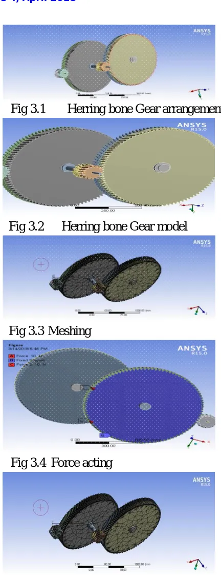
Fig 3.1
Herring bone Gear arrangements
Fig 3.2
Herring bone Gear model
Fig 3.3
Meshing
Fig 3.4
Force acting
ISSN(Online): 2319-8753 ISSN (Print): 2347-6710
I
nternational
J
ournal of
I
nnovative
R
esearch in
S
cience,
E
ngineering and
T
echnology
(A High Impact Factor, Monthly, Peer Reviewed Journal)
Visit: www.ijirset.com Vol. 7, Issue 4, April 2018
KR = 1.0 for 99% reliability KT = 1.0 assuming temp. < 1200C σsf= σsf’ KL KH KR KT = 1174.2 x 0.97 x 1.0 x1 x 1 = 1056.78 MPa
Factor of safety for the pinion against pitting: sH1 = σSf / σH = 1056.78 /984.914 = 1.072
Factor of safety for gear against pitting: sH2 = σSf / σH = 1056.78 /984.914 = 1.072
III. SHAPE OPTIMIZATION ANALYSIS
3.1 MODELING OF THE GEAR
IV. CONCLUSION
Based on the result from the contact stress analysis the hardness of the gear tooth profile can be improved to resist pitting failure: a phenomena in which a small particle are removed from the surface of the tooth that is because of the high contact stresses that are present between mating teeth.
By changing the gear type
•
Elimination of the axial force is takes place.•
The efficiency and effectiveness of the gear box is also improved. By changing the gear materialThe life factor of the internal parts which are used in the gear box was improved. Because of the improved hardness By considering these three factors in our concern, the herringbone gears will be the best choice for wind mill gearboxes
4.1 RECOMMENDATION AND FUTURE WORK
This thesis paper can be an interest for researchers, instructors and postgraduate students who have great enthusiasm to work more on gears. It may give enlightenment about the characteristics of involute herringbone gears and evoke pervious works of various bodies that are involved in gears research and production. Further more this study contribute to a better gear design, assist technological
institutions and all those who are interested in invloute herringbone gears. More work can be done to improve this study and to obtain better output.
S.No Helical Gear Box Herring Bone Gear Box
1. Material – Chrome vanadium Material – Nickel chromium
2. Ultimate Tensile Strength = 13700 kgf / cm2 Ultimate Tensile Strength = 15500 kgf / cm2 3. Produce Axial Force Axial Force is Zero
4.
Life of Gears
Theoretical – 32,000 Hours Actual - 29,000 Hours
Life of Gears
Theoretical – 44,000 Hours
Actual - 40,000 Hours (Assume)
ISSN(Online): 2319-8753 ISSN (Print): 2347-6710
I
nternational
J
ournal of
I
nnovative
R
esearch in
S
cience,
E
ngineering and
T
echnology
(A High Impact Factor, Monthly, Peer Reviewed Journal)
Visit: www.ijirset.com Vol. 7, Issue 4, April 2018
REFERENCES
1. A.A Ross and E.Buckingham Rao, Modeling and Stress Analysis of Helical Gear, Teeth, & structures, 49,pp.1095-1106, 1993.
2. Tsay, C.B., and Fong, Z.H., Computer Simulation and Stress Analysis of Helical Gears with Pinions Circular arc teeth and Gear involute teeth, Mech. Of Mach. Theory, 26, pp.145-154, 1991.
3. Vijayarangan, S., and Ganesan, N., A Static Analysis of Composite Helical Gears Using Three-dimensional Finite Element Method, Computers &Structures, 49,pp.253- 268,1993.
4. Huston, R.L., Mavriplis, D., Oswald, B.F., and Liu, Y.S., A Basis for Solid
Modeling of Gear Teeth with Application in Design and Manufacturing, NASA Technical Memorandum105392,1992.
5. Rao, C.M., and Muthuveerappan G., Finite Element Modeling and Stress Analysis of Helical Gear, Teeth, Computers & structures, 49, pp.10951106, 1993.