On-line Interactive Data Acquisition and
Control System for Embedded Real Time
Applications
Priyanka Patil
1, Dr. Virendra V. Shete
2,Pranali Awate
3PG Student [VLSI], Dept. of ETC, MIT Engineering College, Pune, Maharashtra, India1
Professor, Dept. of ETC, MIT Engineering College, Pune, Maharashtra, India2 Assistant Professor, Dept. of ETC, JSPM’S JSCOE, Pune, Maharashtra, India3
ABSTRACT: This paper is about the application of data acquisition systems in industrial requirements for real time execution of events with industrial process control and automation. The main core of the system is an embedded hardware running a scaled-down version of Linux: a popular choice of operating system for embedded applications. On -line embedded web server is a challenging part of many embedded and real time data acquisition and control system applications. The World Wide Web is a global system of interconnected computer networks that use the standard Internet Protocol Suite (TCP/IP) to serve billion of users worldwide and allows the user to interface many real time embedded applications like data acquisition, Industrial automations and safety measures etc., In this project we approached towards the design and development of on-line Interactive Data Acquisition and Control System (IDACS) using ARM based embedded web server. It can be a network, intelligent and digital distributed control system. Single chip IDACS method improves the processing capability of a system and overcomes the problem of poor real time and reliability. This system uses ARM9 Processor portability with Linux operating system it makes the system which handling various processes based on multi tasking and reliable scheduling mechanisms. A novel approach is introduced to minimize the operational costs while operating with a large amount of data. The system is demonstrated to be suitable for different embedded applications by attaching several real-time modules through appropriate interfaces. The embedded web server technology is the combination of embedded device and Internet technology, through this embedded web server user can access their equipments remotely. The equipment mentioned here could be home appliances and factory devices. This paper is focused on realization of TCP/IP suite and user development platform for this embedded web server. The embedded web server design includes a complete web server with TCP/IP support and Ethernet interface. Web pages are written by Hyper text markup language (HTML).
KEYWORDS: Embedded Arm9 Processor, Linux Operating System, Embedded Web Server, Interactive Data Acquisition and Control System (IDACS).
I.INTRODUCTION
An embedded system is a computer system designed for specific control functions within a larger system often with real time computing constraints. Embedded systems control many devices that are used commonly today and are usually build dedicated to perform a specific task. Embedded systems are especially suited for use in transportation, fire safety, military, and security, medical applications in form of alarm system monitoring abnormal activity or Data acquisition system. The DAS described here provides remote monitoring based on Ethernet. The Ethernet (IEEE 802.3) is the most mature and widely used LAN technology, connecting the embedded device to the network device such as Hub, switch thus realizing a flexible real time control and monitoring has already become an inevitable development trend of embedded technology. In this paper, the design and implementation process of a monitoring system based on ARM9. ARM 9 S3C2440 development kit is connected with PC using a crossover Ethernet cable RJ 45 to provide LAN configuration.
1. Internet based DAQ system.
This method has low operational cost also flexible. Embedded device communicates through General Packet Radio Service (GPRS). So it makes accessible from anywhere in the world through a web server built into the embedded device .GPRS provides a bi-directional real time data transfer allowing Interaction. This system eliminates the need for server software and maintenance. Interactive Internet-based systems provide a way to monitor and adjust using standard web browsers and a PC . The target systems can be monitored and controlled independent from the location and the platform since standard web browsers can be used on the client side.
2.Enhanced Wireless DAS
This method is used mainly in low factory automation. Intelligent remote monitoring technology used in the embedded system of data acquisition for monitoring the output parameters. This DAQ system integrates signal conditioning and processing function into a single board based embedded system by wireless technology using Wi-Fi. It is a flexible method for distributed control and DAQ system .Wireless technology comparatively is best to wired technology in terms of cost, transmission efficiency, data reliability.
3. Data Acquisition With Multi Node Embedded System
In this method Multiple embedded nodes are measuring various industrial parameters to monitor and control industrial process. Data acquired from each node is processed, displayed and sent to master processor (CPLD XC9572) that compile data received from different nodes and send this information to remote location using GSM technology .The master processor process this information and generates controls signals based on predefined cases or can receive the controlling action from remote controller to control the industrial application .This method has low cost, less manufacturing time, ease of implementation with reliable measuring, controlling and data logging demands of industry.
II. GENERAL DESCRIPTION
The Primary goal of building a network connected Data Acquisition system is to build a DAS which would be able to acquire the necessary data from sensors at correct speed and at a correct time and upload and record the values up on an external world through Ethernet. So that system values can be monitored from anywhere without the need of special equipments to receive and display the information in condensed, understandable and legible manner. The information can easily be accessed and controlled by PC, which in turn can be connected to a local low cost local area network (LAN) to transfer sensor values directly to a data logger or computer. The accessibility of this information is significantly curtailed by this need for proximity. However, developments in the Internet protocol TCP/IP, which is the universal communication standard, looks set to change all of this. In order to allow communications to be directed, every physical location on the network (server or client) requires an IP address. Softwares have been designed to run on PC that passes messages received on an IP network to the logger hardware via a serial port or USB.
III. HARDWARE DESCRIPTION
Here we discuss about the design methodology of touch screen based data acquisition. The hardware design consists of S3C2440 ARM9 processor with touch screen, serial port. The touch screen is interfaced to mini2440 development board. The System consists of two nodes first is data acquisition and other is monitoring the sensor data that is acquired. Networked PC Measurement System simply provides a PC-based data acquisition or measurement system with the necessary network interface card and software to serve measurement data over Ethernet. Network communications can be accomplished using a number of different approaches. For example, the PC system could utilize standard networking software provided by Microsoft, such as TCP/IP protocol, remote procedure calls (RPC), distributed component object model (DCOM) or OLE for process Control (OPC).Here we used TCP/IP protocol.
A. S3C2440 ARM PROCESSOR
B. ETHERNET TECHNOLOGY
Ethernet is the most common type of connection computers used in a local area network (LAN). An Ethernet port looks much like a regular phone jack, but it is slightly wider. This port can be used to connect your computer to another computer, a local network, or an external DSL or cable modem. Two widely-used forms of Ethernet are 10BaseT and 100BaseT. In a 10BaseT Ethernet connection, data transfer speeds can reach 10 mbps (megabits per second) through a copper cable. In a 100BaseT Ethernet connection, transfer speeds can get up to 100 mbps. There is also a new technology called "Gigabit" Ethernet, where data transfer rates peak at 1000 mbps. Now that's fast. An Ethernet port is an opening on computer network equipment that Ethernet cables plug into. These ports are alternatively called jacks or sockets. Ethernet ports accept cables with RJ-45 connectors. The term Ethernet refers to the family of local-area network (LAN) products covered by the IEEE 802.3 standard that defines what is commonly known as the CSMA/CD protocol.
C.LM 35 TEMPERATURE SENSOR
The LM35 series are precision integrated-circuit temperature sensors, whose output voltage is linearly proportional to the Celsius (Centigrade) temperature. The LM35 thus has an advantage over linear temperature sensors calibrated in °Kelvin, as the user is not required to subtract a large constant voltage from its output to obtain convenient Centigrade scaling. The LM35 does not require any external calibration or trimming to provide typical accuracies of ±¼°C at room temperature and ±¾°C over a full -55 to +150°C temperature range. Low cost is assured by trimming and calibration at the wafer level. The LM35's low output impedance, linear output, and precise inherent calibration make interfacing to readout or control circuitry especially easy. It can be used with single power supplies, or with plus and minus supplies. As it draws only 60 μA from its supply, it has very low self-heating, less than 0.1°C in still air. The LM35 is rated to operate over a -55° to +150°C temperature range.
D. RJ45 ETHERNET MAGJACK
MAGJACK is a RJ45 cable jack with an in built Ethernet transformer, Status LEDs and Shielding. The Yellow and the Green LEDs in the figure above indicates the Reception and Transmission of Packets respectively. Fig 1: RJ45 Magjack .
Fig 1: RJ45 Magjack
E. UART
The Universal Asynchronous Receiver Transmitter (UART) is a popular and widely-used device for data communication in the field of telecommunication. The Universal Asynchronous Receiver/Transmitter (UART) takes bytes of data and transmits the individual bits in a sequential fashion. At the destination, a second UART re-assembles the bits into complete bytes. Each UART contains a shift register, which is the fundamental method of conversion between serial and parallel forms. Serial transmission of digital information (bits) through a single wire or other medium is less costly than parallel transmission through multiple wires. A UART is usually an individual (or part of an) integrated circuit used for serial communications over a computer or peripheral device serial port. UARTs are now commonly included in microcontrollers. Transmitting and receiving UARTs must be set for the same bit speed, character length, parity, and stop bits for proper operation. The receiving UART may detect some mismatched settings and set a "framing error" flag bit for the host system; in exceptional cases the receiving UART will produce an erratic stream of mutilated characters and transfer them to the host system. Many modern ICs now come with a UART that can also communicate synchronously; these devices are called USARTs (universal synchronous/asynchronous receiver/transmitter).
IV. MEMORY MODULE
Flash in which the BIOS is installed.64M NAND Flash, of which the type is K9F1208U0M, serves as the flash memory of the system. As the hard disc of the system, Nand Flash is mainly used for storage of system boot, OS Kernel, file system, graphical interfaces and application program.
V. SOFTWARE DESCRIPTION
Software design is the main key design of the system. Without the software design hardware will not have any meaning. Software design of this system includes following:
A. TOOLCHAINS AND CROSSCOMILING
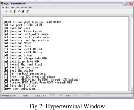
We are probably working on an x86 machine. When we type 'gcc' we are using a compiler that generates machine level code for an x86 processor. This is referred to as a 'native' compiler, as it is generating code for the machine it is running on. We need to generate code for the ARM architecture, so we use a cross compiler, that runs on an x86 machine but generates code for the ARM machine. This is referred to as the target machine. The boot loader is a piece of code that set up the board, finds the kernel, loads it and starts it. UBOOT is a very versatile option for this purpose, and provides many ways to boot up the board. It can boot from flash, SD card and the network. Mini2440 comes with SuperVivi bootloader preinstalled. Before loading uboot first check the size of the NAND memory to decide which version of the pre-built images has to be loaded. Check that the power switch S1 switch is in OFF position; the power led near the switch will be OFF and the switch in the RIGHT position (near the display).As pictured below connect USB, RS232 and power to your board; obviously connect the other side of the cables to the host PC. Then perform the step by step procedure to load Linux kernel and file system also.
Fig 2: Hyperterminal Window
The kernel is the operating system. Currently for this system the kernel provided by Friendly ARM, which can be downloaded from the Friendly ARM website is used. This provides much better board support than other versions of mini2440 kernels. To use this one we will need to adjust the configuration somewhat. There are two tools to use for this 'menuconfig' which is a terminal style configuration utility and 'xconfig' which a GUI tool. While the GUI tool is by far the easiest, if there is a need to do a configuration over telnet, it is a good idea to be familiar with 'menuconfig'.
B. DEVELOPING APPLICATION USING QTOPIA
Q topia provides a graphical environment for the embedded devices and we can develop Q topia application on Linux. No hardware dependencies are required. It can support any processor and graphics card supported by Linux. Requires Linux kernel with linear frame buffer support (4, 8,16 or 32 bit +VGA16 supported).when we create a new project in qt named Hello, we get some files automatically:
- Hello.pro
HelloBase.ui is used for user interface. main.cpp has the main function (entry point) from where your application starts execution. Hello.cpp file contains a class named “Hello”. Hello class is derived from “HelloBase”. Basically this class is generated from UI Compiler along with the .ui class and is derived from QWidget. QWidget is the class that works as a base class for all user interface elements. A Widget is the user interface that receives all types of events, like mouse event, keyboard event, paint event etc. Hello.pro file contains the components that are needed to build the project.
Fig 3: Hello World Application on QT.
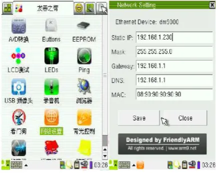
C. NETWORK SETTINGS
In the sub-category "FriendlyARM" process, the point "Network Settings" icon to open the corresponding interface, shown in figure 3. Here, you can set up common network parameters:
- static IP address - the factory default to 192.168.1.230 - subnet mask - the factory default is 255.255.255.0 - gateways - the factory default to 192.168.1.1
- DNS server IP - the factory default is 192.168.1.1 and gateway address the same.
- Card MAC address - this address through the software by the driver settings can be modified, the development board MAC address of the factory are all the same in order to 08:90:90:90:90:90 Point "Save" button then above parameters can be saved and to come into effect immediately restart the development board.
;‘
Fig 4: IP Address Settings
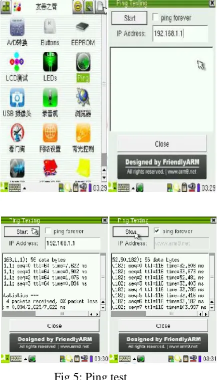
D. PING TEST
Fig 5: Ping test
Point "Start" button to start the ping, point of "Stop" button to stop ping, to close the "Ping Test" the interface will must stop the ping.
VI. RESULTS
The data have been captured in real time and got displayed on both the ends that is on client end (ARM 9) and server end (PC). If the value at sensor (LM35) goes beyond the predefined value then it is turned off the relay and it will show OFF status of the relay through the GUI displayed on the PC screen.
Figure6. Web page sent by Target board to Client
In the fig.6 when we send web page by target board to the client then above fig will display at the client side. by using this client can observe the activity.
Fig.7-web page to change the set point
In fig.7 the web page is displayed by using this client can change the set points to control the activity.
VII. CONCLUSION
The embedded web server that has been designed can be used in educational institutions, offices and many other places. For web-based network element management provide an administrator with a simple but enhanced and more powerful user interface without additional hardware. Poorly designed and configured software architectures might even generate high response time while the physical resources display low utilization. A remote user only requires a common Internet browser to carry out experiments on real hardware. The Embedded web server replaces the PC which is required for remote labs with special hard and software.
REFERENCES
[1] Mukesh Kumar, Sanjeev Sharma, Mansav Joshi,”Design Of Real Time Data Acquisition With Multi Node Embedded Systems”,IJCA,vol.42 No.11,2012.
[2] Manivannan M and Kumaresan N, “Design of On-line Interactive Data Acquisition and Control System for Embedded Real Time Applications”, Proceedings of ICETECT 2011.
[4] Jean Paul Talledo Vilela, Student Member, IEEE, Jose Carlos Miranda Valenzuela, Member IEEE, “Design and Implementation of a Wireless Remote Data Acquisition System for Mobile Applications”, IEEE 2005.
[5] Bhairavi Savant and Rahul Desai,”Deployment of RTLinux on various Platforms,” IEEE conference-ICTESpp. 1058-1062,Dec.2007. [6] S. B. Silverstein, J. Rosenqvist, and C. Bohm, “A simple Linux-based platform for rapid prototyping of experimental control systems,”IEEE
Trans. Nucl. Sci., vol. 53, no. 3, pp. 927–929, Jun. 2006.
[7] Ali Ziya Alkar and Mehmet Atif Karaca,” An Internet Based Interactive Embedded Data Acquisition System For Real Time Applications”,IEEE Trans.Instru.Vol.58,No.3,March 2009.