Prompt gamma rays from
252Cf(sf) and their angular distributions
AndreasOberstedt1,,RobertBillnert2,3,AngéliqueGatera2,AlfGöök2, andStephanOberstedt2 1Extreme Light Infrastructure - Nuclear Physics (ELI-NP) / Horia Hulubei National Institute for Physics and
Nuclear Engineering (IFIN-HH), 077125 Bucharest-Magurele, Romania
2European Commission, DG Joint Research Centre, Directorate G - Nuclear Safety and Security, Unit G.2
Standards for Nuclear Safety, Security and Safeguards, 2440 Geel, Belgium
3Present address: Studsvik Nuclear Environmental AB, 61182 Nyköping, Sweden
Abstract.In a recent measurement of promptγrays from the spontaneous fission of252Cf
an experimental setup was chosen that allowed the study of angular correlations between
γrays and the nuclei from which they were emitted. The observed angular distribution
of prompt fissionγrays was then analyzed to estimate the relative contributions from
radiation of different multipolarity. First preliminary results are presented and compared
to previous angular correlation measurements from different fission processes and recent
results from calculations with the Monte Carlo Hauser-Feshbach code FIFRELIN.
1 Introduction
The energy release in nuclear fission is distributed in kinetic and excitation energy of the two frag-ments. The latter manifests itself in fragment deformation and intrinsic excitation energy. In an early and quite simplified picture, it was assumed that the fragments are first de-excited by the emission of neutrons until the fragments’ remaining excitation energy is lower than the neutron binding en-ergy, i.e. on average at about half of it. Only then de-excitation would continue by the emission ofγ
rays, eventually reaching the ground state [1]. Theseγrays may be divided into two categories, com-monly called statistical and discreteγrays, respectively. The first ones originate mainly from electric dipole transitions and carry away most of the remaining excitation energy of the fragments, while the latter stem mainly from electric quadrupole transitions along the Yrast line and carry away most of the angular momentum of the fragments [2]. This so-called promptγ-ray emission is a fast process,
which basically takes place within the first few nanoseconds after scission [3] and is followed byβ
decay(s) and thereafter by delayed emission of neutrons andγrays towards the valley ofβstability.
The average prompt fissionγ-ray multiplicity, i.e. the average number of photons per fission, amounts
typically to 8 [4], as corroborated by our previous measurements [5–10].
In this work we have chosen an experimental setup that allowed measuring angular correlations between fission fragments and promptγrays, in order to study the de-excitation of the fragments by promptγ-ray emission and to deduce information about the relative contributions from radiation of different multipolarity. Below we compare our observations to those from previous angular correlation measurements and give first preliminary results, which are discussed in terms of results from recent calculations with the Monte Carlo Hauser-Feshbach code FIFRELIN [11].
Figure 1.Sketch of the experimental setup used to measure angular correlations between fission fragments (FF 1 or FF 2) and prompt fissionγrays. The fragments were detected with a cylindrical twin Frisch-grid ionization chamber (FGIC) on whose central cathode a252Cf sample was mounted. For the detection of theγ rays a
LaBr3:Ce detector of size 76 mm×76 mm was employed that was placed along the symmetry axis perpendicular
to the sample. The polar angle of the emitted fragments equivalent to the angle relative to the detected photons is denoted byθ.
2 Experimental setup and data treatment
The recent measurement of PFGS from252Cf(sf) was performed with a 76 mm×76 mm (diameter× length) LaBr3:Ce scintillation detector that was placed perpendicular to the plane of the sample along its symmetry axis. The252Cf sample was mounted inside a cylindrical twin Frisch-grid ionization chamber (FGIC) [12] in the center of a common cathode. Fission fragments from a thin252Cf sample are emitted to both sides of the cathode, ionizing the P-10 counting gas, and being detected by means of the electrons moving towards the respective anodes. A Frisch grid is placed in front of each anode in order to shield the latter from the influence of the ions, but it also allows determining the (polar) emission angle of the fragments (see Fig. 1 for a schematic view of the experimental setup). The FGIC provides the fission trigger for the coincident measurement ofγrays, for which energy and time-of-flight (TOF) between sample and detector are recorded. The latter information is used to distinguish prompt γ rays from other photons, emitted e.g. in prompt fission neutron induced reactions, i.e. mainly inelastic neutron scattering. The experimental techniques applied here are in principle the same as described in Refs. [5–10], where more details may be found.
Figure 1.Sketch of the experimental setup used to measure angular correlations between fission fragments (FF 1 or FF 2) and prompt fissionγrays. The fragments were detected with a cylindrical twin Frisch-grid ionization chamber (FGIC) on whose central cathode a 252Cf sample was mounted. For the detection of theγ rays a
LaBr3:Ce detector of size 76 mm×76 mm was employed that was placed along the symmetry axis perpendicular
to the sample. The polar angle of the emitted fragments equivalent to the angle relative to the detected photons is denoted byθ.
2 Experimental setup and data treatment
The recent measurement of PFGS from252Cf(sf) was performed with a 76 mm×76 mm (diameter× length) LaBr3:Ce scintillation detector that was placed perpendicular to the plane of the sample along its symmetry axis. The252Cf sample was mounted inside a cylindrical twin Frisch-grid ionization chamber (FGIC) [12] in the center of a common cathode. Fission fragments from a thin252Cf sample are emitted to both sides of the cathode, ionizing the P-10 counting gas, and being detected by means of the electrons moving towards the respective anodes. A Frisch grid is placed in front of each anode in order to shield the latter from the influence of the ions, but it also allows determining the (polar) emission angle of the fragments (see Fig. 1 for a schematic view of the experimental setup). The FGIC provides the fission trigger for the coincident measurement ofγrays, for which energy and time-of-flight (TOF) between sample and detector are recorded. The latter information is used to distinguish prompt γ rays from other photons, emitted e.g. in prompt fission neutron induced reactions, i.e. mainly inelastic neutron scattering. The experimental techniques applied here are in principle the same as described in Refs. [5–10], where more details may be found.
The collected prompt fissionγrays were sorted into energy spectra for cosθbins between 0 and 1 in steps of 0.05. In order to obtain emission spectra, the response function of the detector has to be determined, which is usually done by means of Monte Carlo simulations of the actual setup with com-puter codes like e.g. Penelope[13] or Geant4 [14]. Thereafter the response function must be unfolded from the raw spectra. However, as a first step, we have chosen here a different, less time-consuming approach. Adding up all spectra gives an angular integrated raw spectrum that may be compared with others, obtained previously for the same fissioning system. Since they all turned out to exhibit a very similar appearance, we may benefit from the fact that similar raw spectra lead to similar emission spectra, provided that detector and setup are comparable [7]. This is the case here. From a previ-ous measurement [5], for which the proper unfolding was carried out, both measured and emission spectra are known, whose ratio gives a transformation function (see Ref. [7] for details). Multiplying this function with the recently measured PFGS gives then the emission spectrum. In the same way
0 30 60 90 120 150 180
Experiment
Fit
0.90 0.95 1.00 1.05 1.10 1.15
W(
θ
) = I
γ
(
θ
) / A
0
θ
(degrees)
Figure 2.Measured angular distribution of promptγrays from252Cf(sf), depicted as black dots. The error bars
correspond to statistical uncertainties only. The line represents the result of a fit according to Eq. (1).
angular-dependent emission spectra were created for each bin, from which PFGS characteristics were determined. A detailed inspection of the obtained angular distribution is performed below.
3 Angular distribution of prompt fission
γ
rays
As described in the previous chapter, emission spectra of prompt fissionγrays were created for cosθ
bins, covering the polar angle range 0◦ < θ <90◦. The integrated total multiplicity, i.e. the average
number of emitted photons per fission, was determined toMγ =8.28±0.51, where the statistical
uncertainty is 0.07 and the systematic one, mainly due to the transformation function, amounts to 0.44. This result is in good agreement with our last published value Mγ =8.29 ±0.13 [6]. The
angular distribution of radiation may be expressed according to
W(θ)=A0[1+{A2/A0}P2(cosθ)+{A4/A0}P4(cosθ)], (1)
wherePk(cosθ) denote Legendre polynomials for k=2, 4 andθis the emission angle of the fission fragment relative to theγray direction, i.e. perpendicular to the cathode plane of the FGIC. Any possible attenuation coefficients are assumed to be 1. The coefficients{Ak/A0}are determined
experi-mentally and may be compared to theory for different types of radiation. For instance,{A2/A0} ≈ −0.3 for pure dipole radiation and{A2/A0} ≈+0.3 for pure quadrupole radiation, while{A4/A0}is close to zero [15]. Figure 2 shows the measured angular distribution as black dots, together with the result of a fit according to the expression given in Eq. (1) shown as line. It should be noted that the data close to bothθ=0◦and 90◦suffers from considerable instrumental errors due to absorption and scattering, but these points were taken into account anyway, since they did not influence much the fit result. The obtained coefficient is{A2/A0}=0.13±0.03, which according to (+0.3)×p+(−0.3)×(1−p)=0.13 leads top =0.72, corresponding to 72% quadrupole (L=2) and 28% dipole (L=1) radiation (higher
0 1 2 3 4 5 6 This work
binned L = 1 L = 2
10-2
10-1
100
101
102
Photons / (MeV fission)
Eγ (MeV) 0 1 2 3 4 5 6
This work
FIFRELIN L = 1 L = 2 Unknown
10-2
10-1
100
101
102
Photons / (MeV fission)
Eγ (MeV)
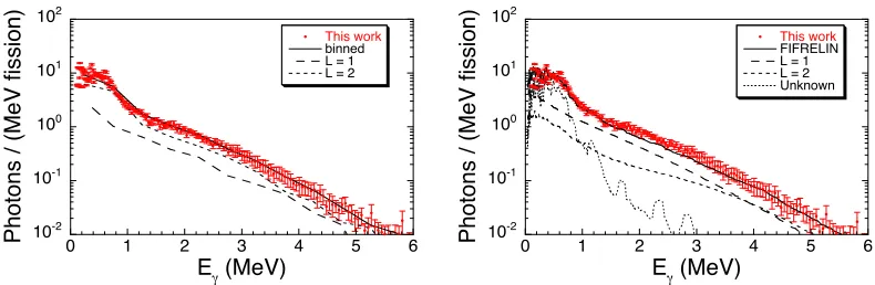
Figure 3. Measured PFGS for252Cf(sf) from this work, depicted by red dots. In the left part it is compared to
the rebinned spectrum of 500 keV intervals (full black line), from which the contributions for dipole (L=1) and
quadrupole (L=2) radiation were determined (long and short dashed lines, respectively). The right part shows in
addition to the measured spectrum a spectrum and its contributions for L=1 and L=2 as well as a contribution
for which the multipolarity is unknown (all three as black lines), calculated recently with FIFRELIN (see text for details).
In the next step we tried to assess how the ratio between quadrupole and dipole radiation depends on the energy of the prompt fissionγrays. For that reason the PFGS was rebinned into 500 keV
inter-vals, for which the corresponding angular distributions were fitted according to Eq. (1) as described above for the entire spectrum. As a consequence, the coefficient {A2/A0}was determined for each
energy bin and the contributions for L=1 and L=2 deduced. The resulting multipolarity-dependent spectra are shown on the left-hand side of Fig. 3. These results are discussed in the next section.
4 Discussion and outlook
Prior to this work, angular distributions of promptγrays were measured in thermal-neutron induced
fission of the target nuclei233U,235U and239Pu [16], as well as the spontaneous fission of252Cf [17]. A
qualitative comparison of all these measurements exhibits a good agreement, indicating a dominating contribution of quadrupole radiation, of which E2 is much more likely than M2. A direct comparison of the coefficients in Eq. (1) from this work and from Ref. [17] has not been made because of the different energy ranges, i.e. only 0.1 to 1.5 MeV are considered in Ref. [17]. However, for the region Eγ =1.0 – 1.5 MeV we obtain{A2/A0}=0.077 and{A4/A0}=-0.022, which is not too far from the corresponding values 0.0683(1) and−0.0308(2) reported in Ref. [17]. If this E2 radiation is assigned toγdecays along the Yrast line (cf. Sect. 1), the corresponding multipolarity-dependent multiplicity would beMγ,L=2 ≈6.0, with a total average multiplicity of Mγ =8.29 [6]. Each quadrupole photon will then carry away 2, which implies an average angular momentum of J≈12, which is in rather good agreement with J≈10reported earlier [18] and results from GEF calculations for different fission fragments [19]. It has to be mentioned though that also lower fission fragment spins of 6
to 8have been reported (see [17] and references therein). Hence, further experimental studies are necessary. The remaining dipole multiplicity would then beMγ,L=1≈2.3 for statisticalγrays.
Calculations based on the Monte Carlo Hauser-Feshbach code FIFRELIN [11] have previously been rather successful in reproducing experimental results for PFGS characteristics as well as the distinct peak structure of the low-energy part of the energy spectra for235U(n
th, f) [8] and252Cf(sf)
0 1 2 3 4 5 6 This work
binned L = 1 L = 2
10-2
10-1
100
101
102
Photons / (MeV fission)
Eγ (MeV) 0 1 2 3 4 5 6
This work
FIFRELIN L = 1 L = 2 Unknown 10-2 10-1 100 101 102
Photons / (MeV fission)
Eγ (MeV)
Figure 3. Measured PFGS for252Cf(sf) from this work, depicted by red dots. In the left part it is compared to
the rebinned spectrum of 500 keV intervals (full black line), from which the contributions for dipole (L=1) and
quadrupole (L=2) radiation were determined (long and short dashed lines, respectively). The right part shows in
addition to the measured spectrum a spectrum and its contributions for L=1 and L=2 as well as a contribution
for which the multipolarity is unknown (all three as black lines), calculated recently with FIFRELIN (see text for details).
In the next step we tried to assess how the ratio between quadrupole and dipole radiation depends on the energy of the prompt fissionγrays. For that reason the PFGS was rebinned into 500 keV
inter-vals, for which the corresponding angular distributions were fitted according to Eq. (1) as described above for the entire spectrum. As a consequence, the coefficient{A2/A0}was determined for each
energy bin and the contributions for L=1 and L=2 deduced. The resulting multipolarity-dependent spectra are shown on the left-hand side of Fig. 3. These results are discussed in the next section.
4 Discussion and outlook
Prior to this work, angular distributions of promptγrays were measured in thermal-neutron induced
fission of the target nuclei233U,235U and239Pu [16], as well as the spontaneous fission of252Cf [17]. A
qualitative comparison of all these measurements exhibits a good agreement, indicating a dominating contribution of quadrupole radiation, of which E2 is much more likely than M2. A direct comparison of the coefficients in Eq. (1) from this work and from Ref. [17] has not been made because of the different energy ranges, i.e. only 0.1 to 1.5 MeV are considered in Ref. [17]. However, for the region Eγ =1.0 – 1.5 MeV we obtain{A2/A0}=0.077 and{A4/A0}=-0.022, which is not too far from the corresponding values 0.0683(1) and−0.0308(2) reported in Ref. [17]. If this E2 radiation is assigned toγdecays along the Yrast line (cf. Sect. 1), the corresponding multipolarity-dependent multiplicity would beMγ,L=2 ≈6.0, with a total average multiplicity ofMγ =8.29 [6]. Each quadrupole photon will then carry away 2, which implies an average angular momentum of J≈12, which is in rather good agreement with J≈10reported earlier [18] and results from GEF calculations for different fission fragments [19]. It has to be mentioned though that also lower fission fragment spins of 6
to 8have been reported (see [17] and references therein). Hence, further experimental studies are necessary. The remaining dipole multiplicity would then beMγ,L=1≈2.3 for statisticalγrays.
Calculations based on the Monte Carlo Hauser-Feshbach code FIFRELIN [11] have previously been rather successful in reproducing experimental results for PFGS characteristics as well as the distinct peak structure of the low-energy part of the energy spectra for235U(n
th, f) [8] and252Cf(sf)
[6]. For comparison, the calculated average PFGS multiplicity has been adjusted to the measured one.
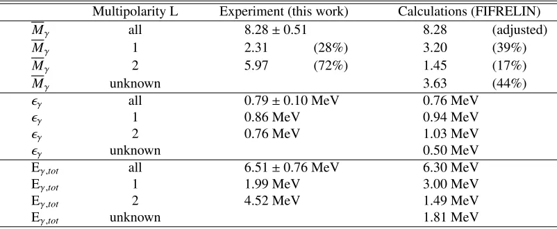
Table 1.Promptγ-ray characteristics for the spontaneous fission of252Cf. Experimental results from this work
for the averageγ-ray multiplicityMγ, the average energy per photonγ, and the total energyEγ,totreleased in
fission, are given for the integral spectrum as well as for the multipolarity-dependent spectra and compared to corresponding values recently calculated with FIFRELIN [22] (see text for details). Relative multiplicities are also given, under the assumption that higher multipolarities may be neglected.
Multipolarity L Experiment (this work) Calculations (FIFRELIN)
Mγ all 8.28±0.51 8.28 (adjusted)
Mγ 1 2.31 (28%) 3.20 (39%)
Mγ 2 5.97 (72%) 1.45 (17%)
Mγ unknown 3.63 (44%)
γ all 0.79±0.10 MeV 0.76 MeV
γ 1 0.86 MeV 0.94 MeV
γ 2 0.76 MeV 1.03 MeV
γ unknown 0.50 MeV
Eγ,tot all 6.51±0.76 MeV 6.30 MeV
Eγ,tot 1 1.99 MeV 3.00 MeV
Eγ,tot 2 4.52 MeV 1.49 MeV
Eγ,tot unknown 1.81 MeV
Even multipolarity-dependent spectra were generated [20], which however seem to show a dominating contribution of L=1 radiation. Apparently, this is in contrast with the experimental results presented in this work, although a considerable part of radiation consists of so-called "experimental transitions", to which no multipolarity was assigned. They were taken from the RIPL-3 database [21]. However, new FIFRELIN calculations were performed recently [22], whose results are shown on the right-hand side of Fig. 3. However, here it must be noted that, apart fromγrays of known multipolarity 1 and 2,
there is a considerable amount of photons, whose multipolarity is not known, since they correspond to transitions between levels taken from the RIPL-3 database (see above). In fact, they constitute about 44% of the calculated total average PFGS multiplicity, as shown in Table 1. Since a dominating contribution of quadrupole radiation has been observed in all PFGS measurements, as referred to above, we tend to conclude that most of these transitions of unknown multipolarity should lead to quadrupole radiation. Therefore, the sum of these "unknown" transitions and the calculated ones with L=2 should be compared to the experimentally obtained contribution for L=2. With this condition comparison of the values given Table 1 shows indeed a rather good agreement.
This agreement would have been even better, if a probably more realistic assumption for the coefficient for pure dipole radiation,{A2/A0} ≈ −0.2, had been made, considering the value{A2/A0}= −0.212(26) from the example given in Ref. [15]. With this value, Mγ,L=1 ≈2.8 and Mγ,L=2 ≈5.5 would have been obtained, corresponding to relative contributions of 34% and 66%, respectively. Of course, these results are still considered preliminary and must be compared with other related information on fission fragments, such as average neutron separation energies and average moments of inertia, in order to verify the deduced energies carried away by dipole and quadrupole photons during the de-excitation process of fission fragments. Hence, these activities are to be continued.
One of the authors (A. O.) acknowledges the support from the Extreme Light Infrastructure Nuclear Physics (ELI-NP) Phase II, a project co-financed by the Romanian Government and the European Union through the
European Regional Development Fund - the Competitiveness Operational Programme (1/07.07.2016, COP, ID
References
[1] C. Wagemans (editor), The Nuclear Fission Process, CRC Press Boca Raton (1991)
[2] A. Hotzel, P. Thirolf, Ch. Ender, D. Schwalm, M. Mutterer, P. Singer, M. Klemens, J.P. Theobald, M. Hesse, F. Gönnenwein, H.v.d. Ploeg, Z. Phys. A356, 299 (1996)
[3] P. Talou, T. Kawano, I. Stetcu, J.P. Lestone, E. McKigney, and M.B. Chadwick, Phys. Rev. C94, 064613 (2016)
[4] R. Vandenbosch and J.R. Huizenga, Nuclear Fission, Academic Press New York and London (1973)
[5] R. Billnert, F.-J. Hambsch, A. Oberstedt, and S. Oberstedt, Phys. Rev. C87, 024601 (2013) [6] A. Oberstedt, R. Billnert, F.-J. Hambsch, and S. Oberstedt, Phys. Rev. C92, 014618 (2015) [7] S. Oberstedt, A. Oberstedt, A. Gatera, A. Göök, F.-J. Hambsch, A. Moens, G. Sibbens, D.
Vanleeuw, and M. Vidali, Phys. Rev. C93, 054603 (2016)
[8] A. Oberstedt, T. Belgya, R. Billnert, R. Borcea, T. Bry´s, W. Geerts, A. Göök, F.-J. Hambsch, Z. Kis, T. Martinez, S. Oberstedt, L. Szentmiklosi, K. Takács, and M. Vidali, Phys. Rev. C87, 051602(R) (2013)
[9] S. Oberstedt, R. Billnert, T. Belgya, T. Bry´s, W. Geerts, C. Guerrero, F.-J. Hambsch, Z. Kis, A. Moens, A. Oberstedt, G. Sibbens, L. Szentmiklosi, D. Vanleeuw, and M. Vidali, Phys. Rev. C90, 024618 (2014)
[10] A. Gatera, T. Belgya, A. Göök, F.-J. Hambsch, M. Lebois, A. Oberstedt, S. Oberstedt, L. Qi, L. Szentmiklósi, G. Sibbens, and M. Vidali, Phys. Rev. C95, 064609 (2017)
[11] O. Litaize and O. Serot, Phys. Rev. C82, 054616 (2010)
[12] C. Budtz-Jørgensen, H.-H. Knitter, Ch. Straede, F.-J. Hambsch and R. Vogt, Nucl. Instr. and Meth. A258, 209 (1987)
[13] http://www.oecd-nea.org/tools/abstract/detail/nea-1525
[14] S. Agostinelli and the Geant4 collaboration, Nucl. Inst. Meth. A506(2003) 250
[15] E.S. Paul, UK Nuclear Physics Summer School, Bristol, 27. August – 6. September 2013, http://ns.ph.liv.ac.uk/ ajb/summerschool/files/ESP-Lecture4.pdf
[16] M.M. Hoffman, Phys. Rev. C133, B714 (1964)
[17] Yu.N. Kopach, P. Singer, M. Mutterer, M. Klemens, A. Hotzel, D. Schwalm, P. Thirolf, M. Hesse, and F. Gönnenwein, Phys. Rev. Lett.82, 303 (1999)
[18] A. Bogachev, L. Krupa, O. Dorvaux, E. Kozulin, M. Itkis, M.-G. Porquet, A. Astier, D. Curien, I. Deloncle, G. Duchene, B.J.P. Gall, F. Hanappe, F. Khalfallah, M. Rousseau, L. Stuttge, N. Redon, and O. Stezowski, Eur. Phys. J. A34, 23 (2007)
[19] K.-H. Schmidt, B. Jurado, C. Amouroux and C. Schmitt, Nuclear Data Sheets131, 207 (2016) [20] D. Regnier, "Contribution à l’étude des gammas prompts de fission", PhD thesis, Université de
Grenoble, France (2013)
[21] R. Capote, M. Herman, P. Oblozinsky, P. Young, S. Goriely, T. Belgya, A. Ignatyuk, A. Koning, S. Hilaire, V. Plujko, M. Avrigeanu, O. Bersillon, M. Chadwick, T. Fukahori, Z. Ge, Y. Han, S. Kailas, J. Kopecky, V. Maslov, G. Reffo, M. Sin, E. Soukhovitskii, P. Talou, RIPL - Reference Input Parameter Library for Calculation of Nuclear Reactions and Nuclear Data Evaluations, Nucl. Data Sheets110(12) (2009) 3107