regime to shock loading
J´erˆome Mespouleta, Fabien Plassard, and Pierre Louis Hereil
THIOT INGENIERIE, Route Nationale, 46130 Puybrun, France
Abstract. The quasi-static mechanical behavior of autoclaved aerated concrete is well-known and can be expressed as a function of its density. There are however not much studies dealing with its dynamic behavior and its damping ability when subjected to a mechanical shock or a blast. This study presents experimental results obtained at the Shock Physics Laboratory of THIOT INGENIERIE company. The test specimens are made of YTONG(TM)cellular concrete with porosity in the range of 75 to 80%. Experimental tests cover a large strain rate amplitude (higher than 104s−1) for specimens up to 250 mm. They were carried out with a small compression press and with two facilities dedicated to dynamic material characterization: JUPITER dynamic large press (2 MN, 3 ms rising time) and TITAN multi-caliber single-stage gas gun. Results in un-confined conditions show an increase of the compressive strength when strain rate increases (45% increase at 5.102s−1) but dynamic tests induce damage early in the experiment. This competition between dynamic strength raise and specimen fracture makes the complete compaction curve determination not to be done in unconfined dynamic condition. A 25% increase of the compressive strength has been observed between unconfined and confined condition in Q.S. regime.
1. Introduction
Autoclaved Aerated Concrete (AAC) has been produced industrially for more 90 years since the actual process was patented by a Swedish architect in 1923. About 15 million m3 of AAC are now produced in Europe per year on 100 production site [1]. This precast product is strong, lightweight, inorganic and non-toxic building material. The increasing needs of thermal efficiency to achieve zero energy consuming housing make the AAC one of the favourite actors in new building construction. A simple confirmation of this fact is the increasing volume production that now attain the equivalent of 300,000 homes built per year in Europe [1].
Numerous quasi-static characterization of this material can be found in the literature for rough or fibber reinforced AAC [2–4] but only few studies have been done in dynamic regime. In this field works have been by Belouettar [5,6] and Pontiroli [7] who investigated its dynamic behaviour.
Utilization of this building material as a damping candidate against shock and penetration events is still explored to mitigate explosive and ammunition threats (blast and fragments impacts). The AAC is referenced as a limiting sympathetic reaction material in ammunition storage in the UK Ministry of Defence (MOD) explosives regulations JSP482 [8] for the safe storage and processing of ordnance, munitions and explosives regulations. A complete and detailed analysis has also been done by Pontiroli et al. in this subject [7]. They presented a work on three densities of AAC with oedometric and triaxial quasistatic characterisation campaign combined
aCorresponding author:[email protected]
Figure 1. Picture of ammunition individual cell storage (left) and
fragments penetration test made in A.A.C. (right) [3].
with penetrations experiments and associated simulations (Fig.1).
Works proposed in this paper are not directly related to those explosive applications but the shock absorption and fragments catching ability of this porous low-cost material makes it a potential actor in the various test configurations that are performed in our laboratory. The collected data obtained during this study will be essential to choose material laws and adjust their parameters for explicit simulation using dedicated software code such as LSDYNA(TM).
The other benefit of this work is to check the ability of our testing machines to be able to test and characterize high area density material in a wide strain rate range.
2. Material description
AAC is composed of sand, limestone, cement and water. A small amount of aluminum powder is then added which induces the generation of hydrogen and by expansion makes the characteristic open cells of aerated concrete.
Figure 2. Pictures of a studied material (left: initial block; right:
close view of the cells on a recovered fragment).
Figure 3. Cumulative cells volume repartition versus solid and
cells diameter (reproduced from [10]).
Hydrogen is then rapidly evacuated by ambient air. Final product is then sliced to appropriate dimensions and inserted in an autoclave that cures it at 180◦C and 10 bar. This process fixes sands and lime and creates Tobermolite crystals or Hydrated Calcium Silicate (C5S6H5).
The material investigated in this study is an AAC manufactured by Xella thermopierre [9] with a nominal density of 550 kg/m3. Pictures of an initial block and a
postmortem fragment of the tested material are proposed on Fig.2.
The repartition of the voids is not uniform in terms of dimension and space position. Two kinds of cells are identified [10]: macro-cells with diameters between 0.5 and 2 mm and micro-cells (below 0.5 mm) (Fig. 3). Pictures on Fig.3show two SEM views at mesoscopic and microscopic scales [10].
The compression strength given by the provider technical sheet is 4 MPa for this density of AAC.
3. Experimental works
3.1. Investigated area
The investigated area covers from quasi-static regime (3 10−3s−1) up to shock loading (>6.0 103s−1) and
different sizes of specimen have been tested to collect maximum data taking into account the capabilities of each facility and associated metrology (peak force for load cell for example).
The quasi-static oedometric tests have been done at CRITT at Toulouse on small sample (Ø20–L30 mm). Two facilities in Thiot Ingenierie Shock Physics laboratory have
Figure 4. SEM pictures of a AAC with microcells (left) and
macrocells (right) (from [10]).
Figure 5. Investigated area: description of testing facilities and
associated specimen dimensions versus increasing strain rate.
been involved to cover the large strain rate amplitude (Fig.5):
• Dynamic compression tests on un-confined 250∗ 250∗150 mm cubic specimen have been done using the large dynamic press JUPITER. This unique equipment is a large dynamic press that is able to generate a stabilized load up to 200 kdaN in a few ms on 1 m3samples,
• Direct impact on Ø80 mm–L50 mm specimen and reverse plate impact experiment with Ø200 mm– L70 mm have been performed with TITAN single stage light gas gun with the 100 and the 220 mm caliber versions.
3.2. Quasistatic oedometric tests
The purpose of the oedometric compression test is to realize a uniaxial compression by keeping the external diameter of specimen constant. For porous material such as AAC, a dedicated confining steel cell is placed below the press stroke and the diameter of the cylindrical specimen is finally adjusted with a very small gap so as to make the lateral expansion of the studied material restricted. The test is performed by applying a force on the top of specimen with a cylindrical steel piston that is well-adjusted to the cell’s inside diameter.
Figure 6. Quasistatic oedometric compression test pictures:
initial configuration with oedometric cell (left); example of initial and post-mortem recovered sample (right).
Figure 7. Comparison of the 3 QS oedometric compression tests
performed in CRITT on Ø20 mm –L 30 mm specimen.
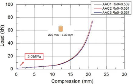
diameter by 30 mm length specimen has been selected to get the full compaction of AAC with the beginning of the solid slope with only half of the allowable press power.
Three specimens have been characterized and all the specimens have been recovered after test (Fig. 6 right). The compaction curves recorded during those tests are presented on Fig.7. Tests were really reproducible and an average crushing pressure at the beginning of the “crushing plateau” has been estimated at 5 MPa in this quasistatic oedometric configuration at 3 103s−1strain rate.
3.3. Quasi-uniaxial dynamic compression test
Dynamic large un-confined compression tests have been done on our large dynamic compression press but dynamic load could reach 5 MN during experiment. Shape and dimensions of the specimens have been updated to take benefit of the extended capacity given by this facility in comparison of what was done at CRITT.
The square shape of the base of specimen was imposed by the compression tools that was available during the tests campaign. A 250 * 250 mm cross section of the AAC sample was selected to obtain the crush pressure and ensure enough stroke power to get the initial portion of the dense response of the AAC once compacted. Pictures of initial setup and recovered specimen post-test are presented on Fig.8.
A high speed camera has been setup to record the compression event at 5,900 frames/s. Frames with 2.04 ms time step for one test are shown on Fig.9between 0 and 18.56 ms. The various frames show that damage occurs very soon in the compaction process and integrity of the
Figure 8. Top: large view of the test configuration. Bottom:
example of dynamic large unconfined compression test: picture of initial setup (left) and recovered specimen (right).
Figure 9. Examples of high speed camera pictures between 0
and 18.56 ms (2.04 ms interframe) obtained during a dynamic compression test with the 250 * 250 * 150 mm cubic specimen.
main specimen is conserved up to 8 ms after the beginning of the compression load. At this time, the displacement of the stroke is 20 mm.
Figure 10. Comparison of the two dynamic compression tests
performed with JUPITER large dynamic press.
Figure 11. Pictures of initial set-up (left) and after test (right)
configuration of direct impact loading configuration.
ensure stress and strain equilibrium. However, the crushing load and by consequence the compressive strength can be evaluated at a value of 4.7 MPa in this unconfined condition.
3.4. Direct impact loading
Direct impact loading on AAC specimen has been explored by Belouettar using a direct impact technique and an instrumented split Hopkinson pressure bar [5]. Tests have been performed with 40 mm cubic specimens made in two different AAC and in dry and wet conditions. The dried tests show a positive strain rate sensitivity of AAC until damage occurs and pulverized the specimen.
For this study, direct impact loading on Ø80 * 50 mm specimen has been done at 25.7 m/s with a 10 mm aluminum thick impactor that gives a 600 g total weight rigid hammer. The nominal strain rate for this experiment
ε/dt =Vi mp/ls with Vi mp the impact velocity and ls the specimen length is evaluated at 515 s−1.
Pictures before and after experiment are shown on Fig. 11. The specimen is mounted on a special device that is instrumented with a dynamic load cell. The compression is recorded with an independent laser based velocity system that gives specimen compression after time integration of the hammer deceleration velocity. A high speed camera has been setup to record the impact event at 20,000 frames/s. All the instrumentation devices are time synchronized using dedicated oscilloscopes.
High speed cameras pictures of the experiment are given on Fig. 12. The various pictures with 50µs time step show that the specimen is compacted all along the experiment but cracks appear and damage occurs and expands 150µs after impact (fourth image on Fig. 12). At this time, the specimen is subjected to the same competition between increasing transmitted load by porous compaction and weakness generated by failure
Figure 12. High speed camera snapshots of direct impact test
between 0 and 400µs (50µs interframe).
Figure 13. Load-compression curve obtained during direct
impact loading at 25.7 m/s on the Ø80 mm – L 50 mm specimen.
and damage expansion than what was observe with the dynamic press n large samples.
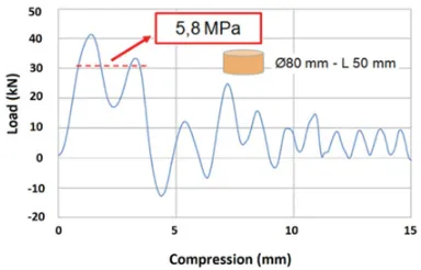
Analysis and comparison of those high speed camera pictures with load given by the force sensor (Fig. 13) confirm the shape of recorded load. On this graph it can be observed that more than 30 kN are transmitted by the specimen up to 4 mm compaction before damage occurs and after the transmitted load decreases down to 10 kN.
The equivalent crushing pressure in unconfined condition is evaluated to be 5.8 MPa based on the 80 mm initial diameter of the specimen.
3.5. Plate impact loading
Figure 14. Side view of the AAC sample inside sabot (left) and
schematic of the reverse plate impact configuration (right).
Figure 15. Free surface velocity- versus time obtained for the
reverse plate impact experiment at 198.5 m/s on Ø200 mm – L70 mm specimen.
Doppler Velocimetry (PDV, or Heterodyne Velocimetry, VH in French).
A side view of the AAC specimen inside the sabot before impact and schematic of the reverse plate impact experiment on the 220 mm launcher are presented here below (Fig.14).
It was decided to do the reverse plate impact experiment with the 220 mm caliber instead of the 60 mm to collect a maximum number of data. This change of diameter allows a longer time record before release lateral waves reach the axis of the aluminum witness plate.
Figure15shows the free surface velocity recorded at of the rear of the aluminum target during the experiment. The fourth first velocity steps observed during the experiment illustrate the reflection of the waves generated by the AAC inside the aluminum target. The velocity steps after 13µs are less pronounced and then show the effect of the release wave that come from the outer diameter of the aluminum witness plate: the 1D condition of wave propagation in the target is then not ensure and so signal is no more representative of the AAC response.
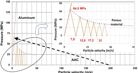
Those reflections are highlighted on Fig. 16with the analytical analysis of pressure versus particle velocity of the reverse plate impact configuration. The pressure at the interface between AAC and aluminum built up following a straight line (dashed arrow on the figure from [198.5 m/s-0MPa] to [3.75 m/s–64.5 MPa]. This curve interacts the aluminum curve and then multi-reflections of shock waves occurs in the Aluminum plate with the aluminum pressure slope. Each reflection at the rear of the Al target is the theoretical level of velocity that will be measured by the
AAC 0
25
0 50 100 150 200 250
Particle velocity (m/s)
Figure 16. Analytical determination of pressure versus particle
velocity generated during the reverse plate impact experiment at 198.5 m/s with the Ø200 mm – L 70 mm specimen on 10 mm aluminum plate.
Table 1. Synthesis of crushing stress obtained during
experimen-tal works on 550 kg/m3AAC.
Strain rate (s−1)
Configuration 3 10−
3 0.3–1.0 102 5.15 102 >6 103
Un-confined
compression 4.0 4.7 5.8 X Confined
compression 5.0 To be done To be done Done
PDV with values of 7.5, 12.8, 17.2 and 21 m/s (given in the top right closed view).
To conclude with this graph, the plate impact test gives only one characteristic point for the AAC in this configuration. This point is defined by using the 3.75 m/s particle velocity (half value of the first free surface velocity record by the PDV) and the 64.5 MPa pressure generated in the aluminum plate. By assuming an error of ±2 m/s on the AAC impact velocity and a±0.5 m/s error on the PDV record, the deduced point is the stress versus specific volume curve of the ACC is 64.5±2.3 MPa for a specific volume of 1.22±0.3 cm3/g).
4. Analysis and future works
A synthesis of crushing stress obtained during this study is presented in Table 1. The results show an increase of compressive stress with the strain rate rising (+45% at 515 s−1). Confined compression versus unconfined property reveal a 25% increase in quasistatic condition. Those tendencies have to be confirmed by future experiments like described here after.
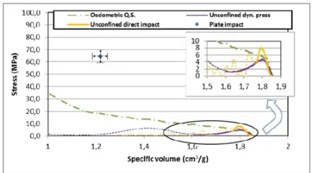
The curves proposed on Fig. 17 gives all the compaction curves results obtained during this study. Only the oedometric quasi-static tests have allowed the complete compaction curves to be obtained. The dashed or dotted lines on unconfined tests show the pressure obtained after damage appears in the experiment. Those phenomenon appear really soon in the compaction process and that means that only the compression strength is achievable with unconfined configurations because complete dynamic response is tricky to perfom with brittle materials.
Figure 17. Stress (MPa) versus specific results obtained during
all the experiments performed in this study.
Reduced scale unconfined and confined configuration using our Ø20 mm Split Hopkinson bars could be an option and can directly be compared to oedometric quasistatic tests performed at CRITT.
A dedicated oedometric cell for the large dynamic press is planned to be done to get AAC response at 102s−1 regime in confined condition and on large samples.
Complementary tests with direct impact loading could be performed at different impact velocities but also in oedometric conditions to collect more data in this low velocity direct impact configuration.
Additional plate impact tests down to 50 m/s and up to 600 m/s need to been done on this launcher. Those tests will give essential data of the reaction of this porous material in high velocity shock loading configuration.
Ballistic tests on AAC blocks will be performed between 10’s m/s and 2 km/s to evaluate the real performance of AAC blocks against penetration events.
Finally, all the collected data have to be finely analysed to select the best material models that will be used in simulation.
5. Conclusion
Wide range of strain rate tests have been done on a dried 550 kg/m3 Autoclaved Aerated Concrete using various facilities. The investigated strain rate range from 10−4s−1 in quasi-static condition up to shock loading higher than 6.103s−1using reverse plate impact configuration.
Results in un-confined conditions show an increase of the compressive strength when strain rate increases but dynamic tests induce damage early in the compressive process (45% increase at 515 s−1). This competition
between dynamic strength raise and specimen fracture makes the complete compaction curve determination difficult to be done in unconfined dynamic conditions
especially because the material show a real brittle and not ductile behaviour once damaged. This study reveal that oedometric experiment are a mandatory with such kind of porous and breakable material.
Comparison in Q.S. regime between unconfined (provider specification) and confined (experiments per-formed in this study) properties reveals a 25% increase of the compressive stress induces the confinement.
Future works will enrich this study with more dynamic tests and especially in confined/oedometric conditions to obtain the compaction curve in dynamic regime.
Ballistics tests have planned to be done between 10’s m/s and 2 km/s on AAC blocks to validate the capacity of this low-cost and easy to provide material for shock absorption and fragments catching.
Finally, this work confirms the ability of our testing facilities to be able to test and characterize high area density materials in a wide range of strain rates.
The authors thank Thiot Ingenierie for funding and express gratitude to Thiot Ingenierie Facility technical staff for doing the experiments.
References
[1] European Autoclaved Aerated Concrete Association, www.eaaca.org
[2] J.F. Argudo thesis, Master of Science Engineering thesis, The university of Texas at Austin (2003) [3] U.M. Cancino thesis, Master of Science Engineering
thesis, The university of Texas at Austin (2003) [4] H. Bagheri, Licentiate thesis, Royal Institute of
Technology, School of Architecture and the Built Environment, Stockholm (2006)
[5] R. Belouettar, J.R. Klepaczko, M.T. Abadlia, Revue Franc¸aise de g´enie civil, 5 (2001), 667–675
[6] R. Belouettar, J.R. Klepaczko, Proceeding of the 9th DYMAT conference, Bruxelles, 1 (2009), 503–509
[7] C. Pontiroli, R. Huet, X.H. Vu, Y. Mal´ecot, L. Daudeville, Proceeding of the 22nd MABS
symposium, Bourges (2013)
[8] JSP 482: Ministry of Defense explosives regulations for the safe storage and processing of ordnance, munitions and explosives, UK (2013)

![Figure 4. SEM pictures of a AAC with microcells (left) andmacrocells (right) (from [10]).](https://thumb-us.123doks.com/thumbv2/123dok_us/8175730.1365429/2.595.73.265.218.346/figure-sem-pictures-aac-microcells-left-andmacrocells-right.webp)