36 | P a g e
COMPARISON OF PID TUNING METHODS FOR
FIRST ORDER PLUS TIME-DELAY SYSTEM
Sami Jan Lolu
1, Gayasud Din Lolu
2,1
Department of Electrical Engineering, Islamic University of Science and Technology,
Awantipora, J&K (India)
2
B. Tech CSE Student, Islamic University of Science and Technology, Awantipora, J&K (India)
ABSTRACT
Controlling the process is the main issue that rises in the process industry. It is very important to keep the
process working probably and safely in the industry, for environmental issues and for the quality of the product
being processed. PID control is a control strategy that has been successfully used over many years. Simplicity,
robustness, a wide range of applicability and near-optimal performance are some of the reasons that have made
PID control so popular in the academic and industry sectors. Recently, it has been noticed that PID controllers
are often poorly tuned and some efforts have been made to systematically resolve this matter. This paper
demonstrates an efficient method of tuning the PID controller parameters using various tuning techniques. It
involves calculating the gain of the controller (Kp), integral time (Ti) and the derivative time (Td) for PID
controlled system whose process is modeled in First order plus time-delay (FOPTD) form. In this paper the
performance of PID tuning techniques is analyzed and compared based on time response specifications.
Keywords
:
Comparison, MATLAB, Performance Specifications, PID Controller, Tuning rules.I. INTRODUCTION
The Proportional- Integral- Derivative (PID) controller is widely used in the process industries. The main reason
is their simple structure, which can be easily understood and implemented in practice.
A PID controller produces an output signal consisting of three terms – one proportional to error signal, another
one proportional to integral of error signal and third one proportional to derivative of error signal. The
combination of proportional control action, integral control action and derivative control action is called PID
control action. The combined action has the advantage of each of the three individual control actions. The
proportional controller stabilizes the gain but produces a steady-state error. The integral controller reduces or
eliminates the steady-state error. The derivative controller reduces the rate of change of error. The main
advantages of PID controllers are higher off stability, no offset and reduced overshoot. According to the survey
37 | P a g e
II. THE PID STABILIZATION PROBLEM
Consider the feedback control system shown in fig.1 where „r‟ is the reference input, „e‟ is the error signal, „u‟ is
the control signal and „y‟ is the output signal. The plant Gp(s) is a first-order system with a transport lag as follows;
(1)
Fig.1Feedback control system
where „K‟ represents the steady-state gain of the plant, „L‟ represents delay time and „T‟ represents time
constant.
The controller Gc(s) is of the PID type having the combination of proportional control action, integral control
action and derivative control action;
(2)
Where is the proportional gain,
;
is the integral time constant,
is the derivative time constant.
Different tuning methods have been therefore proposed in the literature to estimate the three parameters by
performing a simple experiment on an open-loop step response or on a closed-loop feedback system.
III. CONVENTIONAL PID TUNING TECHNIQUES
3.1. Ziegler-Nichols step response method
The Ziegler-Nichols step response method is an experimental tuning method for determining values of the
38 | P a g e
given plants [1]. The first step in this method is to calculate two parameters T (time constant) and L (delay time)
that characterize the plant. These two parameters (T, L) can be determined graphically from a measurement of
the step response of the plant as illustrated in fig 2. First, the point on the step response curve with the maximum
slope is determined and the tangent is drawn with the time axis. Once T and L are determined, the PID
controller parameters are then given in terms of T and L TABLE 1.
Fig.2 Graphical determination of parameters T and L.
The PID controller tuned by this method gives;
= 1.2
= 0.6T (3)
Table.1. PID controller parameters
Type of controller Kp Ti Td
PID
39 | P a g e
3.1.1 Simulation Result:Using this technique on the experimental plant, the PID controller parameters are obtained as mentioned
inTABLE 2.
Table.2. PID controller parameters
Kp Ti Td
3.36 2 0.5
The step response and performance specifications obtained are accordingly shown in fig.3 and TABLE 4.
Fig.3. Step response of the experimental plant
Table.4. Performance specifications
Rise time Peak Amplitude Overshoot
(%)
Time at which
Overshootoccurs
Settling
time
Steady
state
0.192 1.93 93.4 2.08 13.8 1
40 | P a g e
The Ziegler-Nichols frequency-response method is a closed-loop tuning method [1]. In this method, the two
parameters to be calculated are the critical gain Kcrand the corresponding period Pcrwhich can be calculated
experimentally in the following way:
Set the Ti = and Td = zero and hence the controller become in the proportional mode only. The proportional
gain Kpis then increased slowly until a periodic oscillation in the output is observed. This critical value of Kpis
called the critical gain Kcr. The resulting period of oscillation is referred to as the ultimate period Pcr.
Based on Kcrand Pcr, the Ziegler-Nichols frequency response method gives the following simple formulas for
setting PID controller parameters as mentioned in TABLE 5
Table.5. PID controller parameters
Type of controller Kp Ti Td
PID 0.6Kcr 0.5Pcr 0.125Pcr
The PID controller tuned by this method gives;
= 0.1Kcr
= 0.075 (4)
The PID controller has a pole at the origin and double zeros at s = - 4/Pcr.
3.2.1 Simulation Result:
Using this technique on the experimental plant, the PID controller parameters are obtained as mentioned
inTABLE 6 .
Table.6. PID controller parameters
Kp Ti Td
3.4273 1.3675 0.3419
The performance specifications and step responseobtained are accordinglymentionedin TABLE 7 and in fig.4.
Table.7.Performance specifications
41 | P a g e
Amplitude (%) occurs state
0.327 1.98 98 2.08 10 1
Fig.4. Step response of the experimental plant
IV. IMC PID TUNING METHOD
While IMC controller implementations are becoming more popular, the standard industrial controllers remain
the PID controllers [2]. Based on Rivera et al. [1986], the goal of control system design is to achieve a fast and
accurate set-point tracking;
(5)
This implies that the effect of external disturbances should be corrected as efficiently as possible and also being
assured of insensitivity to modeling error;
(6)
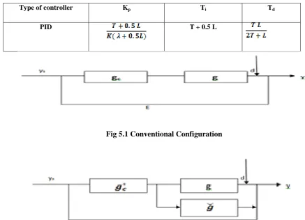
The PID tuning law based on the relationship of the IMC and the PID controller has been proposed by Rivera et
al. [1986]. PID control structure is shown in fig 5.1, where gc and g are the PID controller and the controlled
process, respectively. They are given by;
42 | P a g e
where Kp, Ti, Td are the proportional gain, the reset time and the derivative time, respectively. Meanwhile, the
structures of the IMC is shown in fig 5.2, where and are the IMC controller and the internal model
respectively. The IMC controller is given by
x (8)
where is the filter constant and its value recommended by Rivera et al.[1986] should be greater than 0.8L
because of the model uncertainty due to Pade approximation.
By comparing fig 5a with fig 5b, the following relation is given
(9)
The IMC-PID setting for FOPTD process is given TABLE 8. [2]
Table.8. PID controller parameters for IMC-PID
Type of controller Kp Ti Td
PID T + 0.5 L
Fig 5.1 Conventional Configuration
43 | P a g e
4.1 Simulation Result
Using this technique on the experimental plant, the PID controller parameters are obtained as mentioned in
TABLE 9 .
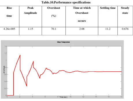
The step response and performance specifications obtained are accordingly shown in fig.6and TABLE 10.
Here is taken 0.9 which is greater than 0.8312.
Table.9. PID controller parameters
Kp Ti Td
2.091 2.9675 0.4286
Table.10.Performance specifications
Fig.6. Step response of the experimental plant
V . CHIEN, HORNES AND RESWICK METHOD
CHR is believed to provide a better way to select a compensator for process control applications [3]. CHR was
developed from the Ziegler-Nichols‟s method for implementation of certain quality requirements of open
Rise
time
Peak
Amplitude
Overshoot
(%)
Time at which
Overshoot
occurs
Settling time Steady
state
44 | P a g e
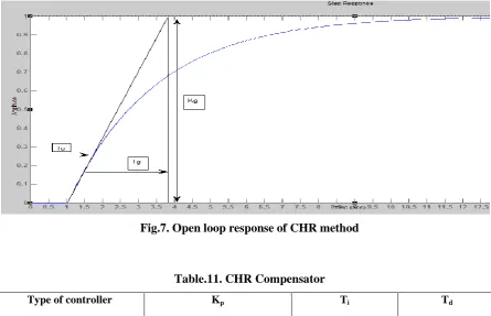
systems. Using a periodic step response as in fig.7, the conditional parameters of the process will be determined
as mentioned in TABLE11.
Fig.7. Open loop response of CHR method
Table.11. CHR Compensator
Type of controller Kp Ti Td
PID 0.6Tg/TuKg Tg 0.5Tu
5.1 Simulation Result
Using this technique, the PID controller parameters and Performance specifications are obtained as mentioned in
TABLE 12 and TABLE13.
Table.12. PID controller parameters
Table.13.Performance specifications
Rising time Peak
Amplitude
Overshoot
(%)
Time at which
Overshoot
Settling time Steady
state
Kp Ti Td
45 | P a g e
occurs3.48e-005 0.966 54.1 2.08 8.27 0.627
The step response obtained is shown in fig.8
Fig.8. Step response of the experimental plant
VI. LAMBDA TUNING METHOD TECHNIQUE
Lambda tuning method is principally a pole placement method. The process model is assumed to be the first
order transfer function [4].
The closed-loop transfer function of the process is desired to be of first order;
(10)
where λ=0.35*L is a tuning parameter that determines the pole location. The parameters of the process will be
determined as in TABLE13.
Table.13 Lambda Tuning PID controller parameters.
Type of controller Kp Ti Td
46 | P a g e
6.1 Simulation Result
Using this technique, the PID controller parameters are obtained as given in TABLE14.
The Performancespecifications and step response obtained from above parameters are given in TABLE15 and
fig.9
Here λ=0.35*L=0.3637.
Table.14. PID controller parameters
Kp Ti Td
2.1156 2.9675 0.4286
Table.15.Performance specifications
Rising time Peak
Amplitude
Overshoot
(%)
Time at which
Overshoot
occurs
Settling time Steady
state
4.17e-005 1.16 71.5 2.08 12.2 0.679
Fig.9. Step response of the experimental plant
VII .PERFORMANCE ANALYSIS
47 | P a g e
(10)
where K=1, T= 2.448, L= 1.039
The MATLAB results for different PID tuning techniques are summarized in TABLE16.
Table.16. Time response Parameters
Tuning Method Rise time Peak amplitude Peak
overshoot
Settling time Steady state
Z-N method 0.192 1.93 93.4 13.8 1
Z-N Frequency
response method
0.327 1.98 98 10 1
IMC method 4.26e-005 1.15 70.1 11.2 0.676
CHN method 3.48e-005 0.966 54.1 8.27 0.627
Lambda method 4.17e-005 1.16 71.5 12.2 0.679
VIII.CONCLUSION
The paper describes design of PID controller for a First-order system with time-delay. Total five PID tuning
techniques were implemented and their performances analyzed. Among them, Ziegler Nichols tuning technique
exhibit largest settling time and maximum overshoot and Chien, Hrones and Reswick Method gives smallest
overshoot and settling time. Among the five PID tuning techniques, the CHR method tuned PID Controller
gives the best results for a First-order time-delay system.
REFERENCES
Books:
[1] K Ogata, “Modern Control Engineering”,Prentice-Hall of India,2003.
[3] R T Stefani, B Shahian, Savant,Hostetter, “Design of feedback control system”s, Oxford University
Press,2002
[4]. A O‟Dwyer. “Handbook of PI and PID Controller tuning rules”, London, Imperial College Press, 2003.
Journal Papers:
[2]. S A Zulkeflee, N Shaari, and N Aziz, “Online Implementation of IMC Based PID Controller for Batch