Invensys Building Systems
O
N
-L
INE
V
ERSION
HVAC C
ONTROLS
I
NTRODUCTION
Pop-up Definitions in this Online Document
• Terms that are blue, italic, and underlined, are provided with pop-up
definitions, which can be accessed through blue “question mark” symbols located in the outside margin.
• To open a definition, simply double-click the “question mark” symbol that
is most in line with the term.
• To close the definition, click the “close” box in the upper-left of the window.
Invensys Building Systems
HVAC C
ONTROLS
Copyright Notice
The confidential information contained in this document is provided solely for use by Invensys Building Systems employees, licensees, and system owners, and is not to be released to, or reproduced for, anyone else. Neither is it to be used for unauthorized reproduction of an Invensys control system or any of its components.
All specifications are nominal and may change as design improvements occur. Invensys Building Systems shall not be liable for damages resulting from misapplication or misuse of its products.
Invensys Building Systems
1354 Clifford Avenue (Zip 61111) P.O. Box 2940
Loves Park, IL 61132-2940 United States of America
Table of Contents
Preface... vii
Purpose of this Document...vii
Appendix A – Supporting Documents for IBS Products ...vii
Glossary...vii
Examples Used in this Document ...vii
Conventions Used in this Document ...vii
Introduction ... 1
Function of HVAC controls... 1
Location of Equipment... 2
Mechanical Room ... 3
Air Handling Units (AHUs) ... 9
Room Controls... 15
Basic Control System ... 17
BASIC CONTROL SYSTEM... 19
Sensor ... 20 Controller ... 22 Controlled Device ... 24 Actuators... 26 Pneumatic Actuators... 26 Hydraulic Actuators... 27
Gear Train Actuators... 28
Direct-Coupled Actuators... 28
Valves ... 29
Control Theory Terminology...36
Setpoint, Control Point, Offset...37
Setpoint ...37 Control Point...37 Controller Action...38 Reset ...44 Reverse Reset ...45 Direct Reset...46
Identifying Reverse or Direct Reset...47
Proportional Control...52
Electronic Direct Digital Control System...52
Throttling Range...54
Proportional with Integral (P.I.) Control ...55
ON / OFF Control...56
Differential ...57
Differential ...57
Floating Control...58
Energy Management Techniques...63
Time-Programmed Commands...64
Duty Cycling ...65
Optimum Start / Stop ...66
Electric Demand Limiting...67
Enthalpy Optimization ...68
Degree Day Calculations...69
Night Purge Cycle ...70
DDC Terminology ...74
Points...75
Digital Inputs...75
Universal Points ... 83
Fixed Point Configuration... 83
Universal Point Arrangement ... 83
Pulse Inputs ... 83
Appendix A ... 84
Glossary ... 91
Abbreviations... 91
Preface
Purpose of this Document
This document serves as an introduction to how a Heating, Ventilating, and Air-Conditioning (HVAC) Control system is used to operate a building’s mechanical equipment so as to maintain the desired environmental conditions.
Appendix A – Supporting Documents for IBS Products
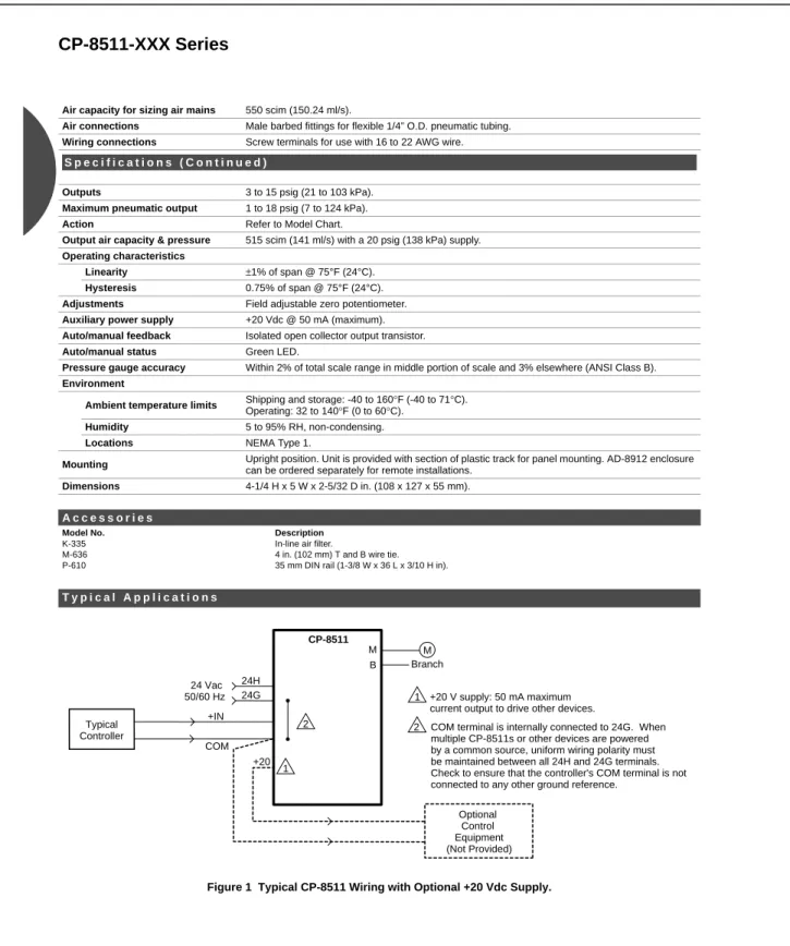
A variety of documents are available to support IBS products. Two samples of these are featured in Appendix A. The first sample shows pages from the IBS Catalog,
supporting the CP-8511 Transducer. The second sample shows pages from a General Instructions sheet that supports the VM Series Erie PopTop™ Modulating Spring-Return Valves. These are meant only as samples and do not represent the entire scope of IBS product support. For complete information on IBS products, consult your local office or wholesale distributor.
Glossary
The Glossary contains a list of abbreviations and alphabetically lists and defines terms used in this document.
Examples Used in this Document
This document contains examples of HVAC equipment and applications. Many of these applications include temperatures, setpoints, throttling ranges, and other examples of conditions found in the HVAC world. When reading this document, keep in mind that these are examples only. Many factors, including equipment, climate, building codes, and local practices vary and can have a major impact on methods, procedures, and sequences used to control buildings.
This document cites examples of products manufactured by Invensys™ Building Systems (IBS). These products represent only a small portion of the IBS product offering, and the applications, features and benefits of IBS controls used in this text represent only their basic functions. IBS has a complete line of products for today’s modern building, offering security, lighting, sophisticated energy management solutions, Internet-accessible reporting and many other products to support the needs of a “smart” building.
Introduction
Function of HVAC controls
A Heating, Ventilating, and Air-Conditioning (HVAC) Control system operates the mechanical equipment (boilers, chillers, pumps, fans, etc.) to maintain the proper
environment in a cost-effective manner. A proper environment is described with four variables: temperature, humidity, pressure and ventilation.
Temperature — The comfort zonefor temperature is between 68°F (20°C) and 75°F (25°C). Temperatures less than 68°F (20°C) may cause some people to feel too cool. Temperatures greater than 78°F (25°C) may cause some people to feel too warm. Of course, these values vary between people, regions and countries.
Humidity — The comfort zone for humidity is between 20% relative humidity (RH) and 60% RH. Humidity less than 20% RH causes the room to be too dry, which has an adverse effect on health, computers, printers, and many other areas. Humidity greater than 60% RH causes the room to be muggy and increases the likelihood of mildew problems.
?
Location of Equipment
Three areas in a building work together to maintain the proper environment. The
HVAC equipment and their controls include the mechanical room, the Air Handling Units
(AHUs) and the individual room controls.
Mechanical Room: Boilers, chillers, pumps, heat exchangers, and other associated equipment are found inside the mechanical room. This area is sometimes called the main equipment room.
Air Handling Units (AHUs): AHUs may be found on the roof, in the main equipment room, or in their own equipment room, which is referred to as the secondary equipment room. AHUs may heat, cool, humidify, dehumidify, ventilate, or filter the air to
Room Controls: Individual room controls regulate the air coming from the AHU to
serve a room or a part of a larger area called a zone. Devices such as wallthermostats
and Variable Air Volume (VAV) boxes provide local temperature control.
There are also room controls not associated with an AHU. These may directly
control mechanical equipment that only serve one room or zone (zone control). These
room controls are installed on equipment such as unit ventilators, fan coil units, andheat
pumps.
Mechanical Room
Heating
The mechanical room may contain a boiler or a group of boilers. The boilers provide
heat for the building. In cooler climates, boilers are large or consist of a number of smaller modular boilers. In warmer climates, boilers are small or even absent from the mechanical room. When enabled, boilers supply a source of hot water that is used by coils throughout the building. The temperature of this hot water may be varied based on the outside
temperature. Note: Hot Water Supply (HWS) temperatures may vary because of the application or the HVAC equipment.
AHU
?
?
?
?
?
?
Most boilers produce hot water, but there are also boilers that produce steam. Boilers develop their heat through gas, coal, oil burners, or electric coils. The previous picture shows a hot water gas-fired boiler. The hot water developed by the boiler is used by hot water coils, which are similar in appearance to car radiators. These coils are found inside the air handling units and, in cold climates, may also be located around the outside walls (perimeter fin-tubes) of the building. In the preceding example, a pump forces water
from the boiler to the coils, then back to the boiler. In cold climates, a normally open (N.O.)
valve is installed to control the volume of water flow through the coil. The amount of flow is
expressed in gallons per minute (GPM) or, in metric units, in liters per second (L/s). The
valve is described as normally open because when no power or control signal is received, the valve goes to 100% open.
Where a steam boiler is used, a steam converter is commonly incorporated into the
design. A steam converter is a type of heat exchanger. Steam provided from the boiler is used to heat water inside the converter. In turn, the hot water developed by the converter is used in the same way as the hot water is used from a hot water boiler. In the example
above, a normally closed (N.C.) valve is used to control the amount of steam going to the
heat steam converter. When no power or signal is received at this type of valve, it closes. Different types of heat exchangers may be used for other applications, including cooling.
?
Water Pumps
Pumps are essential to move the water in a system, whether it is from the boiler to the hot water coils, or from the chiller to the chilled water coils, or from the chiller to the cooling tower. Some applications require at least two pumps so that a standby pump is ready in case something happens to the operating pump. The operating pump is referred to as the lead or primary pump, and the standby pump is the lag or secondary pump.
Cooling
The Chiller is the source of cooling for many buildings. There are a variety of chiller
types. A simple drawing of a centrifugal chiller is shown above. A chiller produces cool
water, for example 42°F (5°C), which is pumped to the chilled water coils inside the air
2) In the chiller, the heat is transferred to a refrigerant, which in turn transfers the heat to the water going to a cooling tower.
3) The Cooling Tower expels the heat to the outside air. The cooling tower is a
container that is open to the atmosphere (Open System), through which water is
passed. When heated water comes from the chiller, it is forced upward to the top of the cooling tower, then sprayed down into the container. Evaporation causes the water to lose some of its heat. To increase the heat loss, fans may be turned on, causing more evaporation. Once the water is cooled to around 85°F (30°C), the water settles in the sump and is sent back to the chiller.
Evaporation is a cooling process that causes some of the water to be lost to the atmosphere. As a result, make up water or fill is needed to maintain the proper water level. Therefore, water in a cooling tower requires water treatment supervision.
There are other ways to cool the condenser water, including cooling ponds or
Review
Mechanical Room
Match the identification number of the mechanical equipment with its name. Matching
1._____ A) Boilers
2._____ B) Hot Water Pumps
3._____ C) Chillers
4._____ D) Cooling Tower
Answers to Review
1. D) Cooling Tower
2. F) Condenser Water Pumps
3. C) Chillers
4. E) Chilled Water Pumps
5. B) Hot Water Pumps
6. A) Boilers
Air Handling Units (AHUs)
Air Handling Units (AHUs) supply conditioned air to a particular part of a building. AHUs can supply different sized areas, whether it is a part of a room, a zone, or an entire group of rooms. In the diagram above, two AHUs supply air to a school auditorium. This
AHU contains a mixed air chamber, a filter, a chilled water coil (commonly called a cooling
coil), a hot water coil (commonly called a heating coil), a fan, and a humidifier. The parts of an AHU are often referred to as the “water side,” composed of those parts that pass water through the AHU, and the “air side,” which is composed of the devices that direct the air within the AHU.
Ventilation requirements determine the minimum position of the outside air dampers. In the winter, when the chiller is shut down, the outside air dampers may open beyond the minimum position to provide cooling. Using outside air for cooling rather than mechanical
cooling is referred to as an economizer mode. During the summer, when the outside air is
too warm to use for cooling, the outside air dampers are set to the ventilation requirement,
which is the minimum position. Exhaust air dampers allow air to leave the building in
proportion to the amount of outside air that enters.
Filters remove dirt particles from the mixed air. It is essential that these filters be replaced periodically. A mixed air sensor is typically located after the filter. This sensor averages the mixed air temperature throughout the cross-section of the duct. This is
important because in mixed air, stratification, which is the layering of the warm and cold air
inside the duct, can occur, possibly resulting in control or comfort problems.
The Supply Fan moves the air through the air-handling unit and out into the rooms.
The amount of air going through the fan may be controlled by the use of inlet vane dampers
(blades that cover the inlet of the fan), or by the use of a variable frequency drive (VFD)
that controls the speed of the fan motor by varying the cycles of electricity. The fan may be positioned before the coils as shown below (blow-through fan) or after the coils (draw-through fan).
The Hot Water Coil heats the air as it passes over the coil. It may be necessary to
heat the air even when providing cooling to a building. This concept may be confusing at first. To help understand this application, it is important to remember that the core of a large building may require cooling year-round, regardless of the outside air temperature. Typically, air used for cooling is delivered to the space at 55°F. If the mixed air
temperature is below 55°F, it may be necessary to heat the air to 55°F for a cooling
application. In the drawing above, the discharge air sensor modulates a two-way normally
?
?
?
?
?
?
The Chilled Water Coil operates during the summer to drop the discharge air
temperature to 55°F (13°C). As shown in the preceding drawing, chilled water is modulated
through the coil by the use of a three-way mixing valve. The valve forces the chilled water
through the coil or bypasses the water around the coil. The Chilled Water coil may also be used for dehumidification of the air, provided the temperature of the cooling coil surface is
below the dew point of the air passing over the coil. The humidity levels are controlled from
a sensor in the rooms being served by this AHU, or by a sensor in the return air duct.
A steam Humidifier, or some other form of humidifier, is placed inside an AHU to
add moisture to the air when needed. Humidity levels, sensed in the return air, are set at 35% RH, for example. The two-way normally closed (N.C.) valve is modulated to maintain 35% RH, plus or minus an acceptable tolerance.
The supply air fan distributes the air into the rooms or zones. After the air has gone
through the zones, it comes back to the Return Fan, which routes the return air back to the
return air dampers or the exhaust air dampers.
?
?
Review
Review
Referring to the drawing on the previous page, match the identification number of the equipment with the correct letter.
Matching
1.__________ A. Supply Fan
2.__________ B. Filter
3.__________ C. Outside Air Dampers
4.__________ D. Return Air Temperature Sensor
5.__________ E. Hot Water Coil
6.__________ F. Mixed Air
7.__________ G. Return Air Dampers
8.__________ H. Return Air Humidity Sensor
9.__________ I. Discharge Air Temp. Sensor
10.__________ J. Return Fan
11.__________ K. Return Air
12.__________ L. Mixed Air Temperature Sensor
13.__________ M. Steam Humidifier
Answers to the Review
1. G. Return Air Dampers
2. J. Return Fan
3. D. Return Air Temperature Sensor
4. H. Return Air Humidity Sensor
5. K. Return Air
6. B. Filter
7. F. Mixed Air
8. C. Outside Air Dampers
9. L. Mixed Air Temperature Sensor
10. A. Supply Fan
11. N. Chilled Water Coil
12. E. Hot Water Coil
13. M. Steam Humidifier
Room Controls
One way to control the temperature in a room is with a Wall Thermostat (stat) that
sends a signal to an actuator that positions a damper to modulate the airflow in a variable
air volume (VAV) box. These VAV boxes are installed in the space between the ceiling tile
and the structural ceiling. This space is sometimes used as a return air plenum, as part of
the building air distribution system.
Actuator
The VAV box has a Damper that modulates to maintain the space temperature by
The airflow regulated by the VAV box is distributed into the space by Air Diffusers. The airflow patterns in a zone or space should not cause people to feel a draft. Two types of diffusers are shown below, but there are numerous other types of diffusers. Air leaving
the room passes through return air grilles, to the return air fan in the AHU.
Air Diffusers
Room controls can also control equipment independent from an AHU. This type of equipment includes fan coil units, unit heaters, unit ventilators, and heat pumps.
A Unit Ventilator, common in schools, is shown above. It serves as the local air-handling unit and has dampers for the outside and return air, a fan, and a hot water coil. The hot water comes from the boiler. The diffusers are on the top of the unit. A space thermostat controls the valve and dampers in this unit. A switch on the base of the thermostat starts the fan inside the unit ventilator.
Fan Coil Units differ from unit ventilators in that they have no dampers. Fan coils are typically installed above ceilings or as console units in a room.
There are many different ways to control the environment of a building. This has only been an overview of some of the equipment that may be encountered.
Basic Control System
An important part of the mechanical equipment is the Control System. Control
systems are the “brains” of HVAC equipment. Pictured below is an AHU that serves only
one zone. This type of AHU is called a single zone AHU. In the example, a temperature
sensor (stat) sends a signal to a control panel, which sends a signal to a valve. These
controls make up a Basic Control System.
A. Sensor B. Controller C. Controlled Devices 1. Actuators 2. Valves 3. Transducers 4. Dampers
Every control system, from the simplest room thermostat to the most complicated computerized control, has four basic elements. The next page a diagram shows an example of a basic control system. A Basic Control System always has these parts. 1. A Sensor monitors and measures a variable. In the example, the
variable is temperature. The sensor provides information to the controller.
2. A Controller receives information from a sensor, selects a portion of that
input for control, and then produces an intelligent output signal. While there may be several other functions performed by controller, all controllers provide
setpoint, sensitivity (differential or throttling range) and action. Details of these terms are cover in the next few pages.
3. A Controlled Device acts upon the signal from the controller. In the example,
the valve is the controlled device, modulating hot water to maintain the proper temperature in the room.
4. A Source of Energy is needed to power the control system. Control systems
use either a pneumatic or electric power supply.
Pneumatic controls use a compressed gas as a source of energy, typically compressed air. Care should be taken to ensure the air supply is clean, dry,
and oil-free. Most HVAC pneumatic controls are powered with 15 to 22 psig.
Electric and electronic controls could be powered by a variety of electrical
power supplies of either Alternating Current (AC) or Direct Current (DC). In the United States of America, the electrical power supplies could be at 20, 24, and 120 volts, 60 Hz. In many parts of Europe, 230 volts, 50 Hz is common.
These four parts are needed in any control system, however, two of these parts may be combined under the same cover, as in the case of some thermostats. While there are occasions when the sensor and controller are combined into one physical device, their basic function remains the same. The sensor, controller, and controlled device are needed for any control system, however an installed system may have additional parts beyond the basics.
The example on the next page shows an electronic-DDC (Direct Digital Control)
system. In this, a type of resistor senses the temperature. The controller in the control panel receives the sensor information and sends an output signal to the valve. The valve/actuator, which is the controlled device, receives the signal from the controller and adjusts to the correct position. Here, electricity is the source of energy. Sensor, Controller and Controlled Device are explained in detail on the following pages.
?
?
?
?
?
?
?
?
?
BASIC CONTROL SYSTEM
Energy Source
Sensor
A sensor monitors and measures a variable. The HVAC variables are temperature, humidity, and pressure. Different types of signals are produced by different types of
sensors.
Electric Controls ON / OFF signals complete or break (close or open) the control signal.
Pneumatic Controls Transmitters sense the variable and produce a 3 psig to 15 psig (pound per square inch, gauge), [20 kPa (kiloPascals) -105 kPa] signal over a particular transmitter's range.
Electronic Controls Types of electronic sensors are:
Resistance sensors are Resistance Temperature Devices (RTDs), and are used in measuring temperature. Examples are Balco elements, Copper, Platinum, 10K
Thermistors, and 30K Thermistors.
Voltage sensors could be used for temperature, humidity and pressure. Typical ranges are 0 to 5 Vdc (Volts direct current), 1 to 11 Vdc, and 0 to 10 Vdc.
Current sensors could be used for temperature, humidity, and pressure. The typical current range is 4 to 20 mA (milliamps).
Examples of sensors are shown below:
?
?
The resistance outputs of a Balco sensor follow the diagrams below:
Electronic Sensor (Balco)
When 1000 ohms is measured across the Balco element, the temperature is approximately 70°F (21°C). As the temperature increases, the resistance changes 2.2 ohms per 1°F (3.96 ohms per 1°C). This is called a Temperature Coefficient of Resistance Curve (TCR Curve). In a Balco, as the temperature increases, the resistance increases proportionally.
Controller
The controller receives the signal from the sensor and produces an output signal with setpoint, sensitivity (differential or throttling range), and action. Types of signals from these devices are as follows:
Electric Controls The majority of electric controls contain the sensor and controller as one piece. Electric controls use ON / OFF signals.
Pneumatic Controls Controller outputs are 3 to 15 psi (21 to 105 kPa).
Electronic Controls There are basically two types of electronic signals.
Voltage outputs may be 0 to 10 Vdc, 2 to 15 Vdc, or other ranges depending on the controller. Voltage outputs have the disadvantage, when compared to current signals, that voltage signals are more susceptible to distortion over long wire distances.
Current outputs modulate from 4 to 20 mA. They have the advantage of producing little signal distortion over long wire distances.
Many controllers are housed inside a control panel. In the case of the DDC electronic controls, the controller itself may be the control panel.
The operation of these controllers is similar. Review the diagram below.
A signal from the sensor is sent to the controller. In this example, 72.5°F (22.5°C) is the setpoint or desired temperature for a room.
The electronic controller has an output of 6 Vdc at 70°F (21°C), and an output of 9 Vdc at 75°F (24°C). This throttling range of 3°F is used to identify the voltage change to temperature change. The output is then sent to the controlled device.
Controlled Device
A controlled device acts upon a signal from the controller. There are a variety of controlled devices. Some examples are;
Electronic Controlled Devices can be either modulating or two-position (ON/OFF).
For example, hydraulic actuators are designed to accept a voltage (Vdc) or current (mA)
signal, while electronic relays are used for two-position outputs.
Electric Controlled Devices are ON / OFF or two-position devices used to control electric heat, DX cooling, and two-position dampers or valves.
Pneumatic Controlled Devices are modulating. Pneumatic actuators are described in terms of their spring range. Common spring ranges are 3 to 8 psig (21 to 56 kPa), 5 to 10 psig (35 to 70 kPa), and 8 to 13 psig (56 to 91 kPa).
Combinations of controlled devices are possible. For example, electronic controllers can modulate a pneumatic actuator. Also, proportional electronic signals can be sent to a
transducer, which converts these signals into proportional air pressure signals used by the pneumatic actuators. These are known as electronic-to-pneumatic (E-P) transducers.
Electric motors with solid state adapters can accept electronic signals.
Pneumatic controllers can provide an output to pressure-to-electric (P-E) switches (on-off or two position control).
An example of a pneumatic actuator is shown below:
This actuator operates with either a pneumatic controller or with an electronic
controller which sends its signal through a transducer.
?
As an example of an electronic controller connected to a transducer, 6 Vdc is
converted into 3 psig, causing the valve to be open. At 9 Vdc, the output from a transducer is 13 psig, completely closing the valve. With a pneumatic controller, 3 psig is sent to the actuator, completely opening the valve. When the controller sends a 13-psig signal to the actuator, the valve strokes to the completely closed position.
Actuators
Actuators are devices that operate valves and dampers. There are several different types of actuators, and four are covered here: pneumatic, hydraulic, gear-train, and direct-coupled.
Pneumatic Actuators
Pneumatic actuators are common controlled devices in the United States. These actuators use compressed air to operate valves and dampers. Pneumatic actuators are easy to repair and can be very cost effective. Specific spring ranges are used for different applications. Spring ranges are selected to provide the most force at close off or to
perform a specific sequence of operations. On a normally open valve, the spring range of 3 to 8 psig (21 to 56 kPa) would be common. On a normally closed valve, the range is
typically 8 to13 psig (56 to 91 kPa). An additional device, a positive positioner, is used on
some actuators to them to perform as if they have a different range, or to provide precise position control. It may also adjust the actuator’s start point, and possibly provide
additional force at the close off of a valve or damper.
Hydraulic Actuators
Hydraulicactuators and valve assemblies are another type of controlled device. The actuator in the diagram above operates on 6 to 9 Vdc. The yellow wire is the signal
provided by a controller, and the blue wire is common, or 0 Vdc. The red wire is a source of +20 Vdc used by certain controllers but is typically not a power supply to DDC control systems controllers. Hydraulic actuators use hydraulic fluid to extend the shaft of the actuator. An internal spring is used to retract the actuator.
Don’t be confused if the IBS hydraulic actuator is referred to as the “beer can” actuator. The term “beer can” has been a slang term used by many IBS offices and customers for years. It is helpful to understand the hydraulic alphanumeric model number system.
IBS Hydraulic Actuators used on both valves and dampers: MA is for Two–Position Control
MA-5200 series is used for electric two-position control of valves and dampers.
MF is for Floating Control
MF-5500 series are floating actuators used in floating control applications
MP is for Proportional Control
MP-5200 series takes a signal of 6 to 9 Vdc and strokes between 6 and 9 Vdc
?
?
Gear Train Actuators
Gear train actuators are electric controlled devices. In the picture above, a box-shaped solid-state drive on the side of the actuator converts the signal (for example, 0 to 10 Vdc or 4 to 20 mA) on the yellow wire to operate the gear train actuator. The blue wire is common and the red wire is a source of +20 Vdc. The gear train actuator may operate in a clockwise or counterclockwise direction. An external linkage must be placed on the actuator to operate a valve or damper. These actuators can develop a large amount of torque, but caution should be taken to ensure that, in spring-return applications, the spring has the necessary power to return the actuator to the fail-safe position.
IBS Gear Train Actuators are MP-300s, MP-400s, MP-2000s, and MP-3000. There are a great variety of features within this product line. The gear train actuators can be used for proportional, floating, and two-position applications of valves and dampers. (See the
close-off ratings in the parts catalog.)
Direct-Coupled Actuators
When used on dampers, direct-coupled DuraDrive™ actuators require minimal or no
?
Valves
Valves are an integral part of a building's operation. Two-way and three-way valves are common. "Two-way" describes the number of ports found on a valve, not the different ways the valve can be piped into a system. Water only flows in one direction through a
two-way valve. Two-way valves come in two types, Normally Open (N.O.) and Normally
Closed (N.C.). The term "normally" refers to the position at which the valve is set whenever power or the control signal is lost. In Invensys globe valves, the “normal” or failed position is based on stem-up.
Normally Open (N.O.)
Normally open valves are typically used on hot water coils in an air handling unit. When the control signal is lost, the valve goes to the fail-safe position, completely open, allowing the available hot water to flow through the coil. Note: Some applications may require the control system to use Normally Closed (N.C.) valves in heating applications.
Normally Open Valve
Normally Closed (N.C.)
Normally closed valves are typically used on chilled water systems. When the controller signal is lost, the valve goes to the fail-safe position, fully closed, stopping all water flow to the coil. In very mild climates, where the threat of freezing is not a major consideration, normally closed valves may be used for both heating and cooling.
Three-Way valves
way valves are another type of valve, so named because of their three ports. Three-way valves come in two types: mixing and diverting.
Mixing valves are used more extensively than diverting valves, due to cost
considerations. A mixing valve is defined as a valve with two inputs and one output. This valve may be used on chilled water coils to divert water through the coil or bypass around it. The use of mixing valves prevents the buildup of water pressure found with two-way valves.
Mixing Valve
A diverting valve is defined as a valve with one input and two outputs. A common use of a diverting valve is with a cooling tower, where the valve diverts water to the top of the cooling tower or bypasses the tower to the sump.
Transducers
Transducers allow electronic controllers to use pneumatic actuators. Transducers convert one type of proportional energy into another. An electronic-to-pneumatic (E-P) transducer converts a voltage or current input into a pneumatic (psig) output.
24H 24G +IN COM +20 OC OE MANUAL AUTO M B
A voltage transducer may convert a 0 to 5 Vdc, 0 to 10 Vdc, or 1 to 11 Vdc signal to a pneumatic signal from 3 to 15 psig. Setup is required to modify the voltage signal to match the desired pneumatic output signal.
Dampers
The proper damper operation is important to a building. The common types of dampers are parallel blade and opposed blade.
Parallel Blade Dampers
Parallel Blade Dampers
Parallel blade dampers are pictured above. Note that the blades of the damper are parallel to each other. Outside air dampers are linked normally closed, so that if any
problem occurs, such as a low limit alarm, the outside air dampers go closed. In this
example, the return air dampers are linked normally open.
Opposed Blade Dampers
Opposed Blade Dampers
The diagram above shows opposed blade dampers in which the adjoining blades of
the damper are positioned in opposite directions. It is important that outside air dampers
Review
Review the previous page and answer the following questions.
Answer questions 1 through 3 by filling in the identification number of the device. Fill in the Blank
1. Which numbered device is a sensor? __________
2. Which numbered device is a controller? __________
3. Which two devices are controlled devices for water? _______ ______
Fill in the Blank
4. Device #1 shows _______________ blade dampers.
5. These dampers control ____________ air.
6. These dampers are linked normally _______________.
7. Device #3 is a __________________.
8. Device #3 converts an ___________ signal into a ____________ signal.
9. Device #2 is a three-way _______________ valve.
Answers to the review 1. 6. 2. 4. 3. 2 and 5 4. Parallel 5. Return 6. Open 7. Transducer
8. Electronic signal into a Pneumatic signal
9. Mixing
Control Theory Terminology
This section covers the following terms:
• Setpoint, Control Point, Offset
• Controller Action
• Reset
• Proportional Control
o Throttling Range
o Proportional with Integral (P.I.) Control
• ON/OFF control
o Differential
Setpoint, Control Point, Offset
Setpoint
Setpoint is the desired condition of a variable that is to be maintained, such as temperature. A room that needs relative humidity to be at 50% RH, or an air handler duct
pressure that is to be 2.0 in. w.c. (inches of water column) (500 Pa) are examples of
setpoints. In the example below, 75°F (24°C) is the room temperature setpoint.
Setpoint
Control Point
The Control Point is the actual temperature being sensed. The Control Point
(temperature) may not be on the setpoint, but instead may be above or below it. Systems operate to maintain the setpoint, plus or minus some acceptable limits called differential (two-position or on/off control) or throttling range (proportional control). Simply stated, setpoint is what you want, while control point is what you get. In the example below, the setpoint is 74°F (23°C), and the control point is at 72°F (22°C), and varying.
?
?
?
?
Controller Action
All controllers, from pneumatic to DDC electronic, have an action. They are either
Direct Acting or Reverse Acting (although other terms may be used).
Direct Action means that the controller's output increases as the sensor's input increases. For example, as room temperature (the variable) changes from 70°F (21°C) to 71°F
(21.5°), the controller changes its output from 10 to 12 mA. Shown below, as the sensor reads an increasing input (temperature), the controller responds by increasing its output (pressure) to the valve, closing the normally open valve and reducing the hot water flow.
This relationship between the input to a controller (temperature) and its output (current) can be displayed on a graph as follows:
?
?
Reverse Action means that as the variable (for example, temperature) increases, the controller's output decreases. For example, as room temperature rises from 70 to 71°F, the controller output decreases from 8.1 to 7.3 mA. In the example below, as the sensor reads an increasing temperature, the controller responds by decreasing its output (pressure) to the valve, closing the normally closed valve and reducing the amount of heating.
The action of the controller must match the proper HVAC application. Normally open heating valves always use direct acting controllers. If a reverse acting controller were to be placed on a normally open heating valve, the heating valve would open as
temperature rises. A reverse acting controller never properly controls a normally open heating valve.
The table below was developed to help determine the correct controller action for different applications. To use the table, first pick the correct application: for temperature, select heating or cooling; for humidity, select humidification or dehumidification; for
pressure, select whether the sensor is downstream or upstream from the controlled device. The second step is to determine how the application fails. Example, does the heat fail to full ON or full OFF? Once these questions are answered, follow the column down and follow the row across to the intersection to find the correct action for that application.
Controller Action
Instructions:1. Pick system application 2. Pick fail safe condition 3. Intersection shows action
Heating Humidification Pressure (sensed downstream from C/D) Cooling Dehumidification Pressure (sensed upstream from C/D)
System
Fails
to
ON
• Normally open ports, valves, or dampers
• Normally closed electric contacts
D.A. R.A.
System Fails to OFF
• Normally closed ports, valves, or dampers
• Normally open electric contacts
R.A. D.A.
Example: In Florida, you are controlling a normally open chilled water valve. In this example, the cooling column is used. In much of Florida, cooling is far more important than heating. Since the valve is normally open, the "Fails to ON" row is used. The column and the row intersect at R.A. or Reverse Acting. As the temperature increases, the signal drops, allowing the chilled water valve to go to its normal open position. As the
temperature decreases, the signal increases, closing the normally open chilled water valve. Controller action is very important. Review the examples on the next page and determine if the controller should be D.A. (Direct Acting) or R.A. (Reverse Acting).
REVIEW
Circle the correct answer.
1. A discharge air sensor modulates a normally open hot water valve. What action is needed for the controller?
Circle the correct answer.
D.A. or R.A.
2. A return air humidity sensor modulates a normally closed chilled water valve for dehumidification. What action is needed for the controller?
3. A static pressure sensor modulates normally closed inlet vane dampers to maintain 2.0" w.c. (500 Pa). What action is needed for the controller?
Circle the correct answer.
D.A. or R.A.
4. A room sensor cycles DX cooling to maintain a room temperature of 75°F (24°C). The DX Cooling has normally open electrical contacts. What action is needed for the
controller?
Circle the correct answer.
D.A. or R.A.
5. The mixed air sensor modulates the normally closed outside air dampers and the
normally open return air dampers to maintain a temperature of 55°F (13°C). What action is needed for the controller?
Answers to the Review 1. Direct Acting 2. Direct Acting 3. Reverse Acting 4. Direct Acting 5. Direct Acting
Reset
The word reset has different meanings in HVAC. Reset in this instance is the
automatic resetting of a setpoint based on a secondary signal. Reset of a setpoint is used for comfort reasons, for better control, or to save energy. A common example of reset is called hot water reset. Hot water reset automatically decreases the hot water temperature setpoint as the outside air temperature rises. If the outside air temperature is 0°F (-18°C), the building requires 180°F (82°C) water. If the outside air temperature is 70°F (21°C), the building requires 90°F (32°C) water. As the outside temperature increases, the hot water setpoint drops.
In every reset application there are at least two sensors. In the example above, the two sensors are outside air temperature (O.A. Temp) and hot water supply temperature (HWS). It is important to know which sensor is the primary sensor and which is the
secondary sensor. To determine which is the primary sensor, ask, "What are the controls
trying to control?" In this example, there is one sensor in outside air and one in hot water. Of these two, the hot water is being controlled, therefore the hot water sensor is the primary
sensor. The outside air temperature sensor is the secondary sensor. The function of the
secondary sensor is to reset, or automatically change, the setpoint of the controller. Each reset application uses a reset schedule. This schedule is determined by the mechanical engineer or the application engineer. A hot water reset schedule is shown on the next page.
RESET Schedule
Just as the term “action” is defined as reverse and direct, “reset” is also defined as
reverse and direct. The hot water reset, above, is an example of reverse reset.
Reverse Reset
The most common of the two types of reset is reverse reset. Reverse reset means that as the signal from the secondary sensor drops, the setpoint of the controller increases. In the example above, as the outside air temperature drops, the hot water setpoint rises.
Direct Reset
With direct reset, as the signal for the secondary input increases, the setpoint
increases. Direct reset is less common than reverse reset. An example of direct reset is an application called “summer compensation”, shown below.
Summer Compensation
When cooling (air conditioning) was first introduced, shopping malls advertised their stores as being a comfortable 72°F (22°C) year round. This was fine until the summer became very hot. People who were outside in 100°F (38°C) weather, dressed for hot weather, would walk into a shopping mall and feel cold. Some people did not stay long in the stores because it felt too cool. Summer compensation is used to counteract this problem. Summer compensation raises the zone setpoint as the outside air temperature increases. The secondary signal and the setpoint go in the same direction. A typical reset schedule for this application may look like the following:
Summer Compensation Reset Schedule
This application is used in any building where a large number of people are entering and leaving all day, such as a shopping mall or bank. If this application is used, it may be important to ensure that the air is dehumidified for proper comfort.
Identifying Reverse or Direct Reset.
Identification of an application as reverse reset or direct reset is possible by looking at the reset schedule and noting the relationship between the secondary signal and the setpoint. If the secondary signal increases as the setpoint decreases, then the application is reverse reset. If the secondary signal increases as the setpoint increases, then it is direct reset.
Secondary Signal and Setpoint go in Opposite directions = Reverse Reset
Review
Review the following applications and answer the questions. Application #1
The hot water supply is maintained by modulating two normally closed steam valves supplying the steam converter.
Hot Water Reset using a Steam Converter
(Circle the correct answer)
1. Which is the primary sensor? Hot Water Supply (HWS)
or
Outside Air Temperature (OAT)
2. What type of reset is this? Direct Reset
or Reverse Reset
3. What action is needed at the controller? Direct Action
or
Application #2
The return air humidity sensor controls the normally closed valve on the steam humidifier according to a reset schedule.
Humidity Reset
4. Which is the primary sensor? Return Air Humidity
or
O.A. Temperature
5. What type of reset is this? Direct Reset
or Reverse Reset
6. What action is needed at the controller? Direct Action
Application #3
The mixed air temperature sensor controls the normally closed outside air dampers and the return air dampers. The mixed air temperature setpoint is reset by the return air temperature, according to the following reset schedule.
Mixed Air Reset
7. Which is the primary sensor? Return Air Temperature
or
Mixed Air Temperature
8. What type of reset is this? Direct Reset
or Reverse Reset
9. What action is needed at the controller? Direct Action
or
Answers to the Review
1. Hot Water Supply
2. Reverse Reset
3. Reverse Action
4. Return Air Humidity
5. Direct Reset
6. Reverse Action
7. Mixed Air Temperature
8. Reverse Reset
Proportional Control
There are a number of control systems that are proportional by their nature, including pneumatics, electronic analog controls, and electronic digital controls.
Electronic Direct Digital Control System
Electronic Direct Digital Controls, better known as Direct Digital Controls (DDC), were introduced to the market in the early 1980s. These controls are electronic and microprocessor based, and require programming to operate correctly. These devices run their programs over and over again. Each time a controller completes its program, it scans (reads) the inputs. A DDC controller may scan as fast as several times each second. With each scan, adjustments are made to the outputs. In the example below, a DDC controller modulates a three-way mixing chilled water valve to maintain a room setpoint of 74°F (23°C).
A Balco element may be used as the sensor, although numerous other sensor inputs can be used, including platinum, copper, or 10K thermistors. These are referred to as RTDs (resistance temperature devices). Other inputs might be voltage, from 1 to 5 Vdc, or current of 4 to 20 mA (milliamps). The controller amplifies the signal and provides a
setpoint, an action, and a throttling range. The controller might optimize the output,
coordinate the output with other controllers, or trend the input and output. Information can be shared with other controllers. The output from the controller goes to the actuator via the
?
?
Proportional control is a common form of control. Proportional control maintains a setpoint with variations above and below that temperature. A graph of proportional control used with room cooling is shown below.
The DDC system on the previous page controls a room with a setpoint of 74°F (23°C). At setpoint, the valve is at midstroke, representing 50% cooling output from the coil*. Suppose there is a large influx of people into the room. People put out heat, causing the room temperature to rise. The controller responds by increasing the signal, extending the actuator and opening the normally closed chilled water valve. Based on the throttling range and the setpoint, each temperature value represents a corresponding actuator position. For example, midstroke is reached at 74°F (23°C). The heavy cooling load resulting from the large number of people entering this space causes the temperature to climb to 76°F (24°C) and the valve strokes to its fully open position. Next, suppose most of the people leave this space, causing a light cooling load. The temperature drops and the actuator retracts, closing the valve completely when the space temperature reaches 72°F (22°C). The preceding two examples show that the temperature can swing anywhere within the 4°F (2°C) throttling range, based on the system’s cooling load.** It is only when the load is at 50% of its maximum that the space temperature matches the setpoint exactly. However, such temperature swings are not noticeable to most people.
*HVAC systems are non-linear. A valve or damper that is 50% open, or at mid-stoke, does not typically equate to 50% flow.
**If the requirement for cooling is beyond the limits of the cooling equipment, the controls may be working properly even though the room temperature is outside the throttling range.
Throttling Range
System Throttling Range (TR) is the change in the measured variable
(i.e. temperature) that causes the controlled device to travel from one end of its stroke to the other. In the example below, it takes a TR of 8°F (4°C) to cause the actuator to travel from the completely open position to the completely closed position.
Throttling range is sometimes referred to as “sensitivity”. Typical throttling ranges are 8° to 10°F (4° to 5°C) for mechanical controls such as mixed air control and the control of hot water supply. In contrast, room controls must be much tighter, with a throttling range between 2° and 4°F (1° to 2°C)
If the throttling range becomes too narrow, it causes the actuator to go into a mode
called hunting. In this mode, the actuator continually searches (or “hunts”) for the proper
controlled position — full open, then full closed; then full open, then full closed, etc. A control system that is hunting, is not in control. It may be possible to eliminate hunting by increase the throttling range so that the controller is less sensitive.
Proportional with Integral (P.I.) Control
Assume that the room that is being controlled has an oversized valve. While there is
no substitute for a properly sized valve, Integral control can make this condition less
objectionable. To stop the actuator/valve assembly from hunting, a wide throttling range 8°F (4°C) may be set. However, room temperature swings of 8°F (4°C) are typically unacceptable and complaints may become common place. A way to correct this situation may be to use proportional plus integral, or P.I., control. Electronic digital controls use this mode of control effectively. Electronic-analog and pneumatic controls can also be set up for P.I. control, but may require considerable time and effort to do so.
Below is a graph of proportional with integral control.
Refer to the graph, above, for an example of how P.I. control works. Note that starting at the left, the temperature matches the setpoint, and the output from the controller is 50%. Then the load changes and there is an offset from the setpoint. The output from the controller starts to compensate, first at 55%, then 60%, then 65% and so forth, until the temperature returns to setpoint. This may cause some oscillation on the part of the
controller, but its output eventually stabilizes. In this example the output, at 65%, took three minutes to stabilize and achieve the 74°F (23°C) setpoint. In other words, every time the load changes, the controller attempts to make the setpoint and the control point the same.
Since any temperature changes are amplified, it is important to make sure the system does not hunt before adding integral control. This means the throttling range may need to be increased, or even doubled, to ensure that the system is stable for P.I. control.
ON / OFF Control
A type of control system where the output is either 0% or 100% is sometimes referred to as “two-position control” or “ON / OFF control”. Mechanical equipment such as
fans, pumps, chillers, boilers, electric heaters and Direct eXpansion (DX) cooling may be
controlled by a two- position control system. In the diagram below, a room sensor monitors the temperature. The controller uses this sensor information to operate a relay output, by using an appropriate program, the correct action, a setpoint, and a differential. Some controller outputs cannot be used directly to control the large amperage of equipment. In that case, a pilot duty relay is used, as shown below.
In the above example, when the room temperature rises, the controller sends a signal to close the pilot duty relay. The normally open contact is then made to common. This
completes the circuit and starts the DX cooling. When the temperature drops, the controller returns the relay output to its open (normal) position, thereby turning OFF the DX cooling.
Differential
A diagram of two-position control as it relates to time and temperature, appears below.
When the temperature reaches 76°F (24°C), the controller turns the DX cooling ON, causing the space to cool. When the temperature has cooled to 72°F (22°C), the controller turns the DX Cooling OFF, causing the space temperature to rise. This 4°F (2°C) swing in temperature is not noticeable to most people. The difference between the temperatures at
which the controller turns ON or OFF, is called the Differential. The differential is similar to
throttling range except that the output is two-position, not proportional. The differential
must be wide enough to prevent short-cycling, which can cause mechanical equipment to
break down prematurely.
The differentialis the change in the measured variable (i.e. temperature) required to
cause the controlled device to go from ON to OFF. The example used in the discussion of throttling range applies here also, with the exception that DX Cooling is cycled from ON to OFF. A 4°F (2°C) differential exists between the temperatures at which DX Cooling comes ON and goes OFF.
There are actually two differentials. Mechanical Differential is the difference in the
temperatures at which the equipment is turned ON or OFF. The other type is the Thermal
Differential, which is the swing that occurs in the actual room temperature. The thermal
Floating Control
Another variation of ON / OFF Control is Floating Control. Below is an example of this application, in which an electric actuator is used to maintain static pressure inside a supply air duct in a VAV air-handling unit.
The DDC controller in this example is controlling an actuator that positions normally closed inlet vane dampers on a supply fan. At start-up, the inlet vanes are closed and the duct static pressure is low. Because the controller is set up to maintain the duct static pressure at 2 in. w.c. (500 Pa), it completes the OPEN circuit. This in turn drives the electric actuator clockwise, causing the dampers to open, thus allowing more air to enter the duct. This does not necessarily mean the dampers are opened fully. Instead, the system opens the dampers just enough to raise the static pressure to the setpoint, inside the differential. Once this pressure is reached, the controller breaks the OPEN circuit.
If the static pressure is too great, the controller completes the CLOSE circuit. This causes the actuator to drive counterclockwise (anti-clockwise), closing the dampers and reducing the airflow, thus lowering the static pressure. Once the static pressure is within the differential, the controller breaks the CLOSE circuit. At setpoint, neither the OPEN nor CLOSE circuits are made, and the actuator "floats" at its last position.
The diagram of static pressure controlled with floating control, is shown below.
At the left of the graph, when duct pressure is 2 in. w.c. (500 Pa), the controller does not respond. As the demand for cooling drops and several VAV boxes begin to close down, the static pressure inside the supply duct rises. It is only the static pressure reaches 2.1 in. w.c. (525 Pa), that the controller responds. At that point, the controller completes the CLOSE circuit and the actuator slowly drives the inlet vane dampers further closed. If the CLOSE contacts stay closed for only 6 seconds, and it takes 120 seconds for the actuator to travel from one end of its stroke to the other, this would mean than the actuator closed the dampers 5%.
When the demand for cooling increases, some VAV boxes open, and static pressure begins to drop. When the pressure reaches 1.9 in. w.c. (475 Pa), the OPEN contacts are made for 12 seconds, so that the dampers are opened by 10%.
Pulsed Width Modulation
A variation of floating control, which is used in DDC controls, is called Pulsed Width Modulation. This type of control pulses the OPEN or CLOSE contact for a certain number of seconds, then waits for the variable (i.e. temperature) to respond. This type of
Review
1. Assume that you are using proportional control. Identify each of the lettered items in
the graph, with one of the terms discussed in this section, then give its present numerical value either in °F or °C.
Term Name Present Value
A
. _____________ _______________B
. _____________ _______________C
. _____________ _______________2. Review the multizone application below, then answer the questions that follow.
(Circle the correct answer)
A. Which is the primary sensor?
Hot Deck Temperature or
Low Temperature Select
B. What type of reset is this?
Direct Reset or Reverse Reset
C. What type of valve is this?
Normally Open or
Normally Closed
Answers to the Review
1. A. Throttling Range 4°F (2°C)
(the output is modulating, not two-position, therefore it is not differential)
B. Offset 2°F (1°C)
C. Setpoint 70°F (21°C)
D. Control Point 72°F (22°C)
2. A. Hot Deck Temp
B. Reverse Reset
C. Normally Open
D. Proportional
Energy Management Techniques
This section covers a number of different strategies used to save energy:
• Timed Programmed Commands
• Duty Cycle
• Optimum Start / Stop
• Electric Demand Limiting
• Enthalpy Optimization
• Degree Day Calculations
• Night Purge Cycle
Before energy management is discussed, it is important to remember that there may be
Time-Programmed Commands
Time-Programmed Commands are an excellent way to save energy. However, this strategy is only effective if a building, or a large portion of a building, has an unoccupied time. During unoccupied time, typically at night, the heating setpoint shifts to 55°F (13°C)
(night setback); the cooling setpoint shifts to 90°F (32°C) (night setup); and lights, fans, chillers, and other mechanical equipment are turned OFF.
Just before occupied time arrives, the heating setpoint shifts to 70°F (21°C) or the cooling setpoint shifts to 75°F (24°C), and the lights, fans, and chillers are turned ON. These temperature setpoints are merely suggestions and may vary. Also, certain types of mechanical equipment, such as a boiler, typically stay ON during winter.
This strategy results in a loss of comfort for those individuals that enter the space during the unoccupied times. If there are individuals who come in after hours, some type of
override is required to turn the lights and mechanical equipment back to an occupied mode.
?
?
Duty Cycling
Duty cycling is a strategy that cycles certain loads, such as small exhaust fans, ON and OFF. For example, exhaust fans may be cycled ON for 20 minutes, then shut OFF for 10
minutes, continuously throughout the occupied time. This is referred to as a fixed duty
cycle. At the end of the day, the OFF time may amount to a large portion of the time. While this strategy may look good on paper, in practice it may not be cost effective. For example, if this strategy is used on large fan motors of 15 hp or greater, there may be no energy savings. That is because the money that is saved during the OFF time could be offset by the large current draw required for starting up the large fan, and the ON and OFF cycles can require more maintenance on the motor belts and other equipment.
A modification of this strategy is called the Temperature Compensated Duty Cycle.
This strategy is used with electric baseboard heaters. If the temperature in the space is 70°F (21°C), the heaters are ON for 1 minute and OFF for 14 minutes. If the space temperature drops to 68°F (20°C), then the heaters are ON for 7 minutes and OFF for 8 minutes. If the space temperatures continue to drop to 66°F (19°C), then the heaters are ON continuously and are not shut OFF until the temperature in the space reaches the setpoint.
Optimum Start / Stop
Optimum Start can be a valuable strategy for saving energy if there are unoccupied times in a building. The optimum start program computes the best, or optimum, time to start the heating or cooling equipment so that at the precise beginning of occupied time, the zone is at the desired temperature. Significant amounts of energy may be saved if the occupied setpoint is achieved as close to occupied time as possible.
Note the example in the chart above. Using only Timed Program Commands (TPC), and identifying the worst possible conditions in which to start cooling, it has been decided that the cooling must be started at 4:00 a.m., 4 hours before occupied time, when it is 95°F (35°C) outside and the zone temperature is 90°F (32°C). This may be a good strategy if these worst-case conditions always exist. However, if the outside air and zone
temperatures are lower, the setpoint will be reached in a shorter time than necessary, wasting energy. As the chart shows, if the outside air is 68°F (20°C) and the zone
temperature is 80°F (27°C), the cooling equipment would achieve the occupied setpoint
2-1/2 hours before occupied time, which is much earlier than necessary. Instead, when
optimum start is used under these cooler conditions, the occupied cooling is started 1-1/4
hours before occupied time. This is much more efficient than the 4 hours chosen in the earlier strategy.
Optimum start is used in the same way for heating. If heat is required in the morning to raise the temperature to the occupied setpoint, the program would automatically calculate the start time so that setpoint is achieved just before occupied time begins. That means that on warmer mornings, the heating equipment is started at a later time than it is on cooler mornings.
The Optimum Stop program calculates a stop time that allows the temperature of
the space to “coast” from the occupied setpoint towards the unoccupied setpoint, while maintaining an allowable comfort level with the least amount of energy usage. For
example, the program would monitor the end of the occupied day and begin turning heating and cooling equipment OFF as people leave the building, to “coast” to the unoccupied
Electric Demand Limiting
Power Demand Limiting is also referred to as EDL.
ELECTRIC DEMAND LIMITING (EDL),
Controlling energy costs is a major concern for today’s building owners. Trying to manage the consumption of electricity is a concern for the utility provider, as well. One strategy that electric companies have instituted to hold down electricity usage is to impose
demand charges, in which the utilities set a demand limit for a facility's electric usage. If this limit is exceeded, the facility pays a penalty, or demand, charge. These demand charges could comprise 30% to 70% of the electric energy bill. An additional problem is that even one excursion beyond the demand limit could increase the utility bill for as long as an entire year. Of course, utility companies and areas vary in the approach taken with consumer utility management, therefore it is suggested that you consult with your providers to ensure your programs are set up correctly.
An effective way to manage demand and limit the number of excursions is to use an Electric Demand Limiting (EDL) program. In this strategy, automation equipment, using EDL, monitors all the demand circuits. Through a technique known as sliding-window data, EDL predicts (forecasts) an expected demand level before it occurs. The forecasted demand level is then compared to the pre-established demand limit. If the forecasted value exceeds this demand limit, the program computes the magnitude of the expected excursion and