Date 17 Feb 2012 Revision 1.5
State Released
European Spallation Source ESS AB Visiting address: ESS, Tunavägen 24
Systems Engineering Management Plan
Name Affiliation Signatures
Author Romuald Duperrier
Systems Engineering Manager ESS AB
Reviewer Johan Lehander
Chairman of the CCB of the programme
ESS AB
Approver James Yeck
Date 17 Feb 2012
TABLE OF CONTENT
1. Introduction... 5
1.1 Purpose and scope ...5
1.2 Definitions, acronyms and abbreviations...7
1.3 References ...9
2. ESS overview ... 10
2.1 ESS basic objectives ...10
2.2 ESS scientific scope ...10
2.3 ESS technical scope...10
2.4 Project schedule...12
2.5 Breakdown Structures ...12
3. Systems Engineering Process ... 14
3.1 ESS Life cycle ...14
3.1.1 The preconstruction phase ...14
3.1.2 The construction phase...14
3.1.3 The operation phase...14
3.1.4 The decommissioning phase...15
3.2 Design reviews...15
3.2.1 External design reviews ...15
3.2.2 Internal design reviews...15
3.2.2.1 Technical cycle ...15
3.2.2.2 Facility Functional Review...16
3.2.2.3 Facility Preliminary Design Review...16
3.2.2.4 Facility Test Readiness Review...17
3.2.2.5 Facility Acceptance Review ...17
3.2.2.6 Facility Operational Readiness Review ...17
3.2.2.7 System formal reviews ...17
3.2.2.8 From system to component formal reviews ...18
3.2.2.9 Deliverables for reviews ...18
3.2.2.10 Incremental development and delivery ...18
3.3 Key Systems Engineering activities ...20
3.3.1 Context identification...20
3.3.1.1 Stakeholders ...20
3.3.1.2 Interacting entities...21
Date 17 Feb 2012
3.3.2.1 Requirement identification...21
3.3.2.2 Requirements Management ...22
3.3.2.3 Requirement Quality Verification ...23
3.3.2.4 Requirement products...23
3.3.3 Operational concept development ...24
3.3.3.1 Definition process ...24
3.3.3.2 Operations Concepts Products and reviews ...25
3.3.4 Architectural design ...25
3.3.4.1 Hierarchy ...25
3.3.4.2 Architectural design via functional and constraint requirements ...25
3.3.4.3 Integrating Reliability Availability and Maintenance and technical risk...27
3.3.4.4 Architecture and design products ...32
3.3.4.5 Trade-off studies, alternative comparisons and off-core activities...32
3.3.5 Implementation...33
3.3.5.1 Detailed design products ...34
3.3.5.2 Engineering model policy...35
3.3.6 Verification, Integration and Validation...35
3.3.6.1 Verification methods ...35
3.3.6.2 Verification products ...35
3.3.6.3 Integration...37
3.3.6.4 Validation...38
3.3.7 Scheduling and Costing support...38
3.3.8 System control ...38
3.3.8.1 Configuration management ...38
3.3.8.2 Traceability management ...39
3.3.8.3 Peer and internal technical reviews ...39
3.3.8.4 Technical Performance Measure (TPMs)...39
3.3.9 Communication ...40
3.3.9.1 Quarterly technical interfaces meetings ...40
3.3.9.2 Collaborations ...40
3.3.9.3 SE activities web site...41
3.3.9.4 SES reporting to SED ...41
3.3.9.5 SED reporting to EPG and CCB of the programme ...41
4. Systems engineering working group principles ... 42
4.1 SE team ...42
Date 17 Feb 2012
4.3 Day to day working groups ...42
5. Systems Engineering Management... 43
5.1 Systems engineering office ...43
5.2 Roles and Responsibilities ...43
5.2.1 The SED ...43
5.2.1.1 The Systems Engineering Manager...43
5.2.1.2 The SE Risk manager ...43
5.2.1.3 The Requirements, architecture and RAM SE manager...44
5.2.1.4 The Safety SE manager...44
5.2.1.5 The ESS platform library manager...44
5.2.2 Other teams and offices...44
5.2.2.1 The Systems Engineer for an ESS project ...44
5.2.2.2 The Integration and Design Support Division ...45
5.2.2.3 The Lead engineer...45
5.2.2.4 The System owner...45
5.2.2.5 The design engineer ...45
6. Systems Engineering Products ... 46
6.1 Guidelines ...46
6.2 Templates ...46
6.3 Systems engineering documentation tree ...47
7. Systems Engineering Tools and meta data ... 48
7.1 Architecture and data export...48
7.2 Object attributes ...49
7.2.1 Requirements...49
7.2.2 Product (PBS node) ...52
7.3 Communication outputs ...55
7.4 Plan for tool selection ...55
8. Other Systems Engineering activities ... 56
8.1 Integrated Logistic Support...56
8.2 Standards and terms ...56
8.2.1 Standards and Units ...56
Date 17 Feb 2012
1. INTRODUCTION
1.1 Purpose and scope
Because the future ESS facility is a system consisting of a huge numbers of interacting systems and contributors, it is considered crucial to implement a systematic approach to organize and to control the ESS implementation process from design to decommissioning [1]. Systems Engineering – SE - is an interdisciplinary approach and means to support the successful realization of such complex systems [2].
The need for Systems Engineering arose with the increase in complexity of systems and projects, in turn exponentially increasing the possibility of component friction, and therefore the reliability and safety of the design. When speaking in this context, the absence of a systematic and coordinated approach will also lead with a high probability to overheads and delays.
A coordinated approach allows a holistic view that enhances the quality of the system of interest and the configuration management during the implementation when change requests are unavoidable. In this view, it is mandatory to trace the expectations for a system at all relevant levels.
SE focuses on defining the user needs and the required functionalities early in the development cycle, documenting requirements, then proceeding with design synthesis and system validation while considering the complete problem.
The ESS Systems Engineering Management Plan - SEMP - is intended to describe the technical processes, associated roles, products and tool features that will be used by the ESS team to support the construction programme.
The level of detail in the system descriptions to be developed has to be adapted in accordance with the impact of the failure of the system of interest (technical, licensing, organisational, financial, operational). This implies that the approach defined in this plan will have to be graded in accordance with a predetermined set of criteria to be identified. While this plan aims at detailing a comprehensive toolkit for conducting systems engineering activities during the ESS construction, the graded approach requires that participants focus their effort as sequenced below:
1. Requirements and verifications definition, 2. Integration of the safety in the design,
3. Integration of the operational aspects in the design.
The first stage is a prerequisite for establishing a solid foundation regarding the execution of the two latter stages.
The ESS Systems Engineering Management Plan execution will take benefit of all pre-existing initiatives to develop SE activities. Where the design is initiated, it is proposed to collect the expected performances and functions, to identify their interfaces and subsystems. Where the analysis of requirements is being performed, it is proposed to analyse and format the results of the process in order to make them compliant with the ESS generic approach developed in this SEMP. Throughout the SE process, the existing engineering documentation will populate consistently a structured technical configuration
Date 17 Feb 2012
Each pre-existing cross-functional working group will find in the SE framework a space in which they will enhance their interactions with other groups.
It is assumed that this customized approach will gradually lead all systems in a holistic perspective putting the design teams in a supplier-provider relationship which supports an unambiguous identification of the interfaces.
The SE process aims at integrating the technical risk and the safety aspect at all levels of abstraction of the design activities. In this respect, dedicated workshops will support the definition of safety requirements and the process will trace the required changes of the architecture for enhancing the system safety and mitigating the risk.
Throughout the SE process, a review process supports the assessment of any product for readiness to further development activities.
This SEMP is applicable to all technical tasks to be performed in support of the ESS construction programme [3]. This document will be placed under change control upon its initial release. The Systems Engineering Division – SED - will update the SEMP until the end of the construction phase.
Date 17 Feb 2012
1.2 Definitions, acronyms and abbreviations
Term Definition
AFC Administration and Finance Committee BoM Bill of Materials
CAD Computer Aided Design CB Collaboration Board CCB Change Control Board CDR Critical Design Review CEO Chief Executive Officer
CMP Configuration Management Plan COTS Commercial Off The Shelf CSV Comma Separated Values DMS Document Management System
DU Design Update
EPG ESS Project Group
ESS European Spallation Source
FMECA Failure Modes Effects and their Criticality Analysis FTA Fault Tree Analysis
FR Functional Review
IDSD Integration and Design Support Division INCOSE INternational Council On systems Engineering LBS Location Breakdown Structure
MBSE Model Based systems Engineering MTA Maintenance Task Analysis OMG Object Management Group PLM Product Lifecycle Management PM Preventive Maintenance PMO Programme Management Office PBS Product Breakdown Structure
PHS&T Packaging, Handling, Storage and Transportation PSI Paul Scherrer Institute
RAM Reliability Availability Maintainability
RASEM Requirement and Architecture Systems Engineer Manager SAC Scientific Advisory Committee
SAR System Acceptance Review
SE Systems Engineering
Date 17 Feb 2012
Term Definition
SEMP Systems Engineering Management Plan SES System Engineer for a ESS System SET Systems Engineering Team SHE Safety, Health and Environment SNS Spallation Neutron Source SoI System of Interest
STAP Scientific and Technical Advisory Panels
System owner Person responsible for the delivery of a verified system TAC Technical Advisory Committee
TBC To Be Confirmed
TBD To Be Determined
TBS To Be Scheduled
TPM Technical Performance Measure TRR Test Readiness Review
Date 17 Feb 2012
1.3 References
[1] Systems Engineering Policy, ESS-0000967. [2] IS0/IEC 15288:2008, System life cycle processes.
[3] Programme Plan for the European Spallation Source, ESS-0001122. [4] Change Control Process, ESS-0001879.
[5] Design Process Specification, ESS-0002411. [6] Configuration Management Plan, ESS-0003688. [7] ISO/IEC WD4 42010 – Architecture Description. [8] Requirement Development Guidelines, ESS-0003068. [9] Radiation Safety Assessment at ESS, ESS-0000050. [10] Risk Management Process, ESS-0000263.
[11] T-book, Reliability Data of Components in Nordic Nuclear Power Plants, 6thEdition,
Studvik AB.
[12] Change Control Process, ESS-0001879.
[13] OMG Systems Modeling Language, Version 1.2,
http://www.omg.org/spec/SysML/1.2/. [14] http://europeanspallationsource.se
Date 17 Feb 2012
2. ESS OVERVIEW
2.1 ESS basic objectives
The basic objectives for the ESS facility are to provide world leading neutron scattering methods for European science, striving for scientific excellence and highest performance in terms of scientific results. The facility is in all its parts designed to meet these objectives and to satisfy European demand for both cutting edge capability and research capacity. In meeting these objectives, the ESS will provide new knowledge unattainable with other facilities or methods and strengthen science and underpin innovation in Europe.
2.2 ESS scientific scope
ESS will have a unique ability to study a broad range of structures and time scales due to its long, high-intensity neutron pulses. ESS will offer neutron beams of unparalleled brightness, delivering more neutrons than the world's most powerful reactor-based neutron source, and higher peak intensity than any existing spallation source. The high flux will enable many investigations to be pursued that are out of range today, by allowing faster measurements, measurements of smaller samples, the increased use of polarised neutrons and detection of weaker signals. The bright neutron beams will be delivered in a unique time structure, with long neutron pulses at low frequency. This structure enables the efficient use of long-wavelength neutrons. Novel neutron technologies will exploit this structure to allow ESS instruments to achieve a wider dynamic range, bi-spectral beams, and tunable resolution as needed, all of which will significantly expand scientific possibilities. State of the art methods for data management and analysis will further enhance capacity and capability.
2.3 ESS technical scope
The main components of the ESS facility are the accelerator, the target station, the instrument suite and the associated buildings and infrastructure.
In the accelerator, protons are accelerated to an appropriate energy for efficiently driving a spallation reaction. The ESS accelerator is designed for high power and high reliability and uses mainly superconducting cavities.
The target station will convert the proton beam from the accelerator, through a spallation reaction, into a number of intense beams of slow neutrons. The technology chosen for the target is that of a rotating wheel. A moderator-reflector assembly surrounding the target transforms the fast neutrons produced in the spallation reaction into slow neutrons. These slow neutrons are guided to the instruments.
In the instruments, the neutrons will be used for probing the properties of materials in a wide sense. The Data Management and Software Center in Copenhagen (DMSC) provide support and services for the management and scientific analysis of the data.
In addition to these parts there is an infrastructure of services, supporting laboratories and workshops, offices and amenities for staff and users. Figure 1 presents a preliminary layout of the site north east of the city of Lund, Sweden.
Date 17 Feb 2012
11(71) Figure 1: Preliminary facility layout.
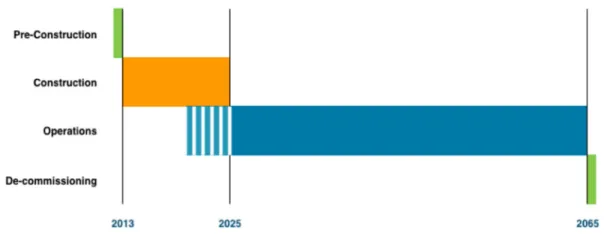
Date 17 Feb 2012 2.4 Project schedule
The
Figure 1 shows the master schedule of the ESS construction up to the delivery of a fully operational facility [3]. This schedule encompasses the major milestones for the pre-construction, construction and operation phase, the first neutrons to instruments and the expected full beam power on target.
Figure 1: ESS Master Programme schedule.
2.5 Breakdown Structures
The Work Breakdown Structure – WBS – is a hierarchical tree-like depiction of the development activities as they relate to:
The ESS system architecture,
The ESS life cycle,
The ESS specific collaborative scheme, especially the in-kind contributions,
The present “green field” status of ESS AB.
During the construction phase, a significant proportion of the technical activities will be performed by teams whose members are from several geographically diverse organizations. Funding and control of these remote tasks and activities is one of the major challenges of the ESS construction phase. For each phase, the WBS will be broken down and maintained by the programme team.
Date 17 Feb 2012
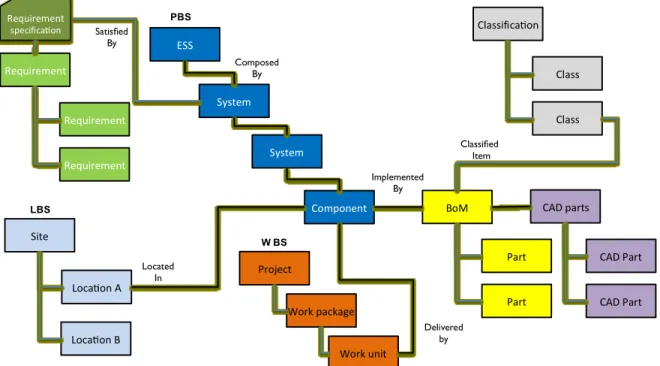
The Product Breakdown Structure – PBS – is a hierarchical tree-like decomposition of the facility into its constituting elements. The PBS reflects the architecture of the ESS system. Typed trace-links will establish the relationships between the PBS elements and other structure items and documents. In this respect, the PBS will be an entity aggregating several types of information related to a system (see Figure 2).
A PBS element is the product of an activity of the construction phase. A PBS node can represent either a software item or a hardware item. A “leaf” of the PBS is named component. This entity will be the connection point for generating a Bill of Materials, itself connected to a CAD structure if applicable. The BoM associated to a component may be an instance of a centralised classification or ESS catalogue. This mechanism will support standardisation and reduce the engineering effort by reutilizing already engineered BoM. Any of the elements depicted in the figure below may be trace-linked to a document.
It will be possible to trace-link a PBS node to a Location Breakdown Structure node for specifying the location of a system. The history of the relationships shall be maintained by the PLM system for e.g. supporting future decommissioning activities. Indeed, it shall be possible at any point in time of the ESS life cycle to determine when and where equipment was used. This also means that the Location Breakdown Structure will contain information related to zoning.
Figure 2: Breakdown structures.
ESS System System Component BoM Part Part Requirement Requirement Requirement Classifica on Class Class Site Classified Item Satisfied By Implemented By PBS Located In Composed By Requirement specifica on CAD parts CAD Part CAD Part Loca on A Loca on B LBS Project Work package Work unit W BS Delivered by
Date 17 Feb 2012
3. SYSTEMS ENGINEERING PROCESS
3.1 ESS Life cycle
Related standards: ISO15288:2008 Clause 6.2.1
The Figure 3 shows the ESS programme life cycle master phases. It applies to any ESS system.
Figure 3: ESS life cycle phases. 3.1.1 The preconstruction phase
This phase focuses on the baselining process for the ESS facility. Starting from the 2003 baseline, this Design Update – DU - subproject will provide a preliminary design prior to the construction phase. The main deliverables of the pre-construction phase are described in reference [3].
The deliverables of the preconstruction phase will make use of the experience of the contributing partners worldwide and lessons learnt in existing facilities such as SNS, PSI or Isis. During this phase, a contingency budget will be defined to cover commodity price fluctuations and the possible extra cost induced by the necessary adaptation of the state -of-art hardware to the particular needs of ESS. The consolidation of these adaptations will be carried out through engineering modelling early during the construction phase. In this context, the ESS design will implement COTS and state-of-art components as much as possible.
3.1.2 The construction phase
The construction phase encompasses the activities which will transform and integrate each pre-design of the preconstruction phase into products ready for the ESS operation. The construction phase will end in 2025 after completion of the 22 instruments suite.
3.1.3 The operation phase
The operation phase of ESS will occur over time starting with the operation of major accelerator and target systems as well as the first instruments in 2019 and continuing with the final commissioning and handover into full operations with 22 neutron instruments in place 2025. The expected duration of the operation of the ESS with its nominal or possibly upgraded performances is 40 years.
Date 17 Feb 2012
3.1.4 The decommissioning phase
After its utilization period, the facility will be decommissioned during a period of 7 years for restoring a green field status to the hosting site.
3.2 Design reviews
3.2.1 External design reviews
Monitoring of the development will be performed by external reviews [3]. These reviews are described in the following table. These reviews will occur during the whole construction phase.
Field of interest Concerned systems Committees
Technical Accelerator and Control
systems ATAC
Target and dump systems TTAC
Conventional Facilities CFAC
Scientific and Technical Instruments suite STAP, SAC
Safety Safety related systems TBD
Construction Programme ESS Annual review committee
3.2.2 Internal design reviews
Related standards: ISO15288:2008 Clause 6.2.1, ISO10007:2003 3.2.2.1 Technical cycle
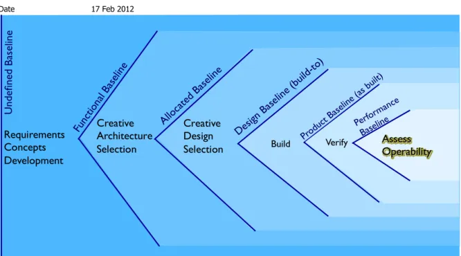
The technical baseline will evolve from its functional form to its operational form throughout the SE process. The Functional Baseline will depict the functional view (requirements and use cases or concepts of operation) of the ESS. Definition of the Allocated Baseline will support the setting up of the architectural aspect (requirements allocation and interfaces). The defined allocated baseline will be transformed gradually into a Design Baseline via detailed engineering activities. Design specifications of the design baseline will enable the manufacturing/procurement the ESS products and their associated documentation that will constitute the Product Baseline. All verified products and their associated documentation i.e. verification results will establish the Performance Baseline. Throughout these technical activities, the ESS team will reduce the scope of possible technical solutions and will increase the resolution of the facility architecture descriptions up to obtaining the Operational Baseline (see illustration in Figure 4).
Date 17 Feb 2012
Figure 4: Tollgates for system development maturity.
3.2.2.2 Facility Functional Review
The ESS Facility Functional Review – ESS.FFR – is a formal internal review chaired by the programme director. The CCB of the programme members and the EPG members comprise the review board. The ESS.FFR is held to ensure the objectives and requirements are understood by the affected and associated ESS programme stakeholders.
The Functional Review examines the functional, constraints (including safety and environment) and performance requirements defined for the ESS facility. The review addresses the relevancy of the proposed requirements and use cases.
The Facility Requirement Document (system requirements) and the Concepts of Operations for the ESS facility (stakeholders’ requirements and use cases) documents will be draft by the SE office and will be the major inputs for the review.
This review is the first tollgate prior to the release of the requirement for hardware and software design. After passing this first tollgate the requirement tree and the use cases - the functional baseline - will be placed under configuration control [4].
3.2.2.3 Facility Preliminary Design Review
The ESS.PDR examines the proposed facility architecture and the flow down of requirements to ESS systems. It assesses the need for further breakdown of the architecture. It ensures that the technical risk and the safety aspects are addressed.
The facility architecture (internal structure and interfaces, requirements breakdown and allocation to systems) will be specified in the Facility Architecture Specification. This document will identify the need for Interface Control Documents between the ESS systems.
The CCB members comprise the review board of the PDR. The PDR will be the first internal review of the architecture and in this respect, once complete, it will define the PBS at level 1
Requirements Concepts Development Creative Architecture Selection Creative Design Selection Build U nd efi ne dBa se lin e Func tiona l Bas eline Alloc ated B aselin e Desig n Base line ( build -to) Produ ctBa seline (asbu ilt) Assess Operability Perfor mance Baselin e Verify
Date 17 Feb 2012
and 2. This review will initiate the allocated baseline and ensures that all requirements are allocated to ESS systems.
3.2.2.4 Facility Test Readiness Review
The facility ESS.TRR ensures that the facility, its test equipment, support personnel, and test procedures are ready for the verification of the facility. This review examines the produced documentations by the acceptance reviews for the ESS systems (see below) and the verification plan for ESS.
The TRR presided by the chairman of the CCB of the programme will in principle precede the last verification activities of the construction that will complete the performance baseline.
3.2.2.5 Facility Acceptance Review
The ESS.SAR examines the facility, its end products and documentation, and inspection, demonstration, test data and analyses that support its verification. The ESS Acceptance Review ensures that the all system requirements have been satisfied and that the validation activities can start.
The ESS.SAR presided by the chairman of the CCB of the programme will complete the performance baseline by approving the ESS verification results (ESS verification report).
3.2.2.6 Facility Operational Readiness Review
The ESS.ORR examines the actual facility characteristics (e.g. spare parts availability), results of the validation activities and ensures that the ESS AB personnel and procedures have reached the required maturity.
The ORR chaired by the ESS CEO will establish the operational baseline that will be the ultimate set of work products of the technical baseline.
3.2.2.7 System formal reviews
All ESS systems will rely on the same review process than the facility. Refinement of the requirements and concepts of operation for a particular system will be assessed by a system Functional Review to be performed at the level 2, then at level 3, etc. Further breakdown of the PBS will be granted by a Preliminary Design Review. Throughout this approach, new “leaves” of the PBS tree-like structure will be identified. Each of these items or components will permit the generation of an associated Bill of Materials (see section Error! Reference source not found.
and 3.2.2.8). Reuse of the already engineered system from the classification will be possible by connecting an instance of a class to a PBS component and will support standardisation. A component will only be the subject of a CDR (see section hereafter), a TRR and a SAR. The requirement document for a component will be first derived from its allocated requirements during the PDR of the upper level system. The requirement specification is amended if needed during the detailed design activity.
Prior to any verification activity, similarly to ESS, a system test readiness review will assess the maturity of the resources for supporting the verification activities for a system (test stand accessibility, test equipment readiness, availability of the personnel).
Once the verification activities are performed, a system acceptance review prior to integration will be held. The system is then delivered to the team responsible for the upper level.
Date 17 Feb 2012
3.2.2.8 From system to component formal reviews
The system life cycle will include a detailed engineering phase (design and build or procure). When homemade design is performed, a Critical Design Review concludes the design activity. The CDR assesses if the design meets all system requirements with acceptable risk and within the cost and schedule constraints.
The CDR demonstrates that the maturity of the design is appropriate to support proceeding with full-scale fabrication, assembly, integration, test, and future operation and decommissioning.
Design activities between the PDR and the CDR for a system of interest will comply with the design process as defined in the reference [5].
3.2.2.9 Deliverables for reviews
Review Deliverables Level of interest
FR System Requirement Document
Concepts of Operation System
PDR System Architecture Specification
Interface Control Documents
System Verification Plan
System
CDR System Requirement Document
System Design Description and related documents (drawings, P&ID, etc)
Interface Control Documents
System Integration Plan
System Operation and Maintenance Manual
System Verification Plan
Component
TRR System Verification Plan Component and system
SAR System Verification Report
Verified products
System Integration Plan
Component and system
ORR ESS Validation Report
Validated products ESS
3.2.2.10 Incremental development and delivery
From 2019, the operation will start while the construction activities will continue and will be completed by the end of 2025. In this respect, increments will be developed and delivered that allow for assembly into an operational system with limited functionality with later increments that add increased functionality.
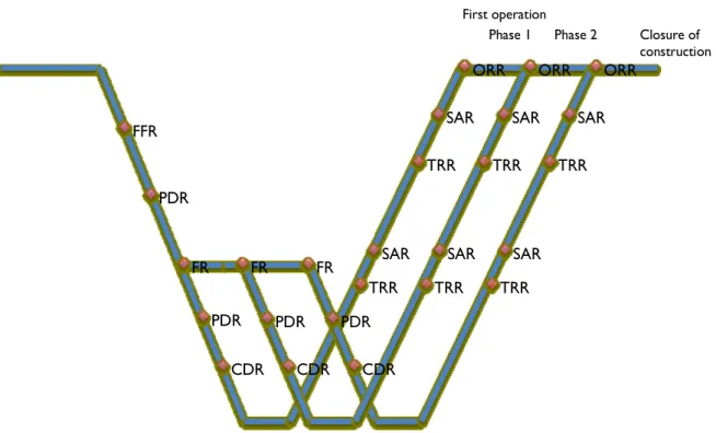
The Figure 5 illustrates this feature: successive deliveries will upgrade the facility in operation (e.g. from 1 to 22 instruments).
Date 17 Feb 2012
Figure 5: The incremental development and delivery cycle for ESS construction.
Figure 6: ESS design reviews master schedule.
FFR PDR FR FR CDR CDR CDR TRR TRR TRR FR PDR PDR PDR TRR TRR TRR
SAR SAR SAR
SAR SAR SAR
ORR ORR ORR
Phase 1 Phase 2 Closure of construction First operation
Requirement
definition Architecturedefinition Implementation Verification
Validation and handover phase 1 Validation and handover phase 2 Validation and handover phase 3 FR May 2013 PDR Oct 2013 TRR July 2019 SAR Nov 2019 ORR Dec 2019 ORR Dec 2022 ORR Dec 2025
Date 17 Feb 2012
3.3 Key Systems Engineering activities
Key Systems Engineering activities will be developed throughout the pre -construction and construction phases up to and including the validation phase. The major SE activities include:
Environment identification (stakeholder, interacting entities),
Requirement identification and management,
Operational concepts or use cases definition,
Architectural design (interfaces),
Integrate Reliability, Availability, Maintainability and Safety in the design process,
Assess technical risk for dimensioning performance contingencies.
All these activities are iteratively performed at different levels. Each activity contributes to the refinement of the others. The verification activity is initiated just after the requirement definition activity to:
1. Ensureadequacy of the verification and the requirement set, 2. Identify the design constraints induced by verification activity.
During the construction phase the technical activities shall be monitored to ensure that trace links between requirements and verification activities are maintained as well as ensuring the efficient management of non-conformities and change requests. In this respect, the SE process is an essential part of the configuration management process [6].
The description of the SE process for ESS will be hereafter based on textual and light processes specifications. Indeed, the figures describing the processes will not show the flows of products and the roles associated to each activity. A detailed process map is depicted in Appendix A.
3.3.1 Context identification
Related standards: ISO42010:2009, ISO15288:2008 Clause 6.4.1 3.3.1.1 Stakeholders
Requirement elicitation shall be first based on the analysis of the system stakeholders. Indeed, stakeholders’ knowledge is means for identifying the various viewpoints from which the views constitute the ESS architecture descriptions (see Figure 7). In this respect, ESS stakeholders will be identified and classified throughout SE model like the “onion” model.
Date 17 Feb 2012
3.3.1.2 Interacting entities
Identification of the ESS interfaces will be defined via workshops with the ESS developers. Context diagrams will be established and converted into an ESS context diagram. The workshops will determine the interacting entities and their relationship with the ESS system (client/supplier or other perspective).
3.3.2 Requirements
Related standards: ISO15288:2008 Clause 6.4.1 and 6.4.2 3.3.2.1 Requirement identification
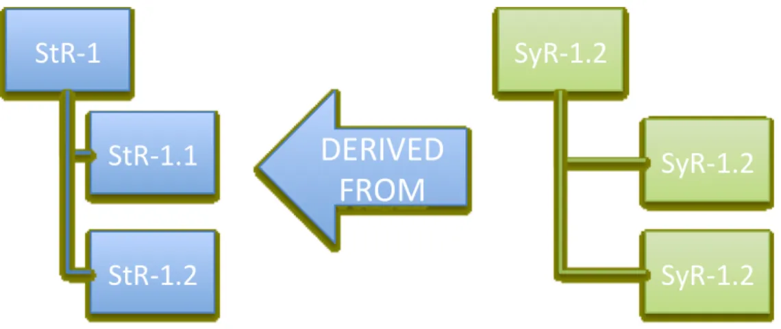
The ESS requirements will be organized into two tree-like hierarchies. Figure 8 shows how the requirement trees are related. The first tree will contain the stakeholder’s requirements defined from the ESS statutes and other sources like collaboration agreements. From this first tree, the ESS system requirement tree will be derived. This second tree will provide the mechanism for specifying what is necessary down to the lowest level of the system for each state of the life cycle. System requirements are also defined by integrating the context view related to the interacting entities. Each requirement is traced to its source and contained specific attributes. The ESS system requirements will be organized in three categories. First category is functional requirements that is the “what” is performed by the system. The second category is constraint requirements that is the “How” a function is performed. Both functions and constraints can be associated to a set of performance requirements, which constitutes the third category, the “How well”. This last category:
Either quantifies the satisfaction level of a functional or a constraint requirement, e.g., temperature between 300 and 350 K,
Or qualifies the satisfaction conditions of a requirement (e.g.: compliance with a standard).
The kinship between functions, constraints and performances is mandatory to properly build the requirements tree and provide the necessary trace links for change request management. During the requirements definition activity, working groups will take care that the following principles are respected:
each requirement is necessary,
each requirement is unique,
each requirement is verifiable, (NB avoid “optimize”, “maximize” or “minimize” which are unverifiable statements in many cases),
ensure that each phase of the life cycle is addressed,
for performance requirements, state the units and the tolerance (x±y unit). The requirements can be further labelled for enhancing sorting with additional categories:
Interface, Safety, Radiation safety, Conventional safety, Electrical, Environment, Regulatory, Operational, Maintenance, Testability, Supportability, Usability,
Instrumentation and Control,
Structural,
Date 17 Feb 2012
Some requirements flow between elements or are common amongst all elements:
Electrical systems requirements,
Electromagnetic Interference/Electromagnetic Compatibility (EMI/EMC) Plan,
Environment, Safety and Health objectives, and
Standards and norms.
These requirements might be documented in dedicated documents as reference - ESS standards - to be called in the requirement tree.
Figure 8: ESS requirements trees relationship.
3.3.2.2 Requirements Management
One common database for tracking ESS requirements (ESS requirements tree) will be set up and maintained. This database will be part of the ESS platform CHESS, which will host the ESS meta-model. It shall be ensured when requirements are recorded into this common database that each item has the followed attributes filled-in:
Responsible,
Tracelink to other requirements (derived, contained),
Source and/or Rationale,
Verification method,
Technical Risk Id if applicable (the risk being the source),
Priority,
Status.
The requirement responsible will be by default the system owner for which the requirement has been allocated to. The “derived” relationship will be the relationship between requirements from two different specifications. All requirements allocated to a system will constitute the requirement specification for this system. The tracelink “contained by” will define the relationship of the requirement within a specification. In this respect, “contained by” relationship may used as a “refined by” relationship.
The source attribute is a reference to a document stored in the document management system. The document is preferably the result of an analysis (functional, risk, trade-off, maintenance task, fault tree, failure mode effect).
StR-1
StR-1.1
StR-1.2
SyR-1.2
SyR-1.2
SyR-1.2
DERIVED
FROM
Date 17 Feb 2012
All pre-existing requirements packages developed so far by different stakeholders will be analysed and possibly reformulated to enable their consistent integration in the ESS requirement tree (see Figure 9).
Figure 9: Integration process of pre-existing requirements in the ESS database.
3.3.2.3 Requirement Quality Verification
Programme participants with the support of the SET will make sure that each system requirement satisfies criteria in section 3.3.2.1, the required trace links exist and are valid, each requirement is verifiable and the verification activity is valid, the attributes of the requirement are complete and consistent. The SET will perform quality audits for reporting to the CCB and EPG the current status of the requirement definition activity.
3.3.2.4 Requirement products Facility level
The ESS facility requirements document –FRD- serves as the top-level for the requirements flow-down. It encompasses the scientific requirements and facility constraints. Once uploaded in CHESS by the SED, the FRD will be issued to EPG one couple of weeks before the facility functional review. The FRD is a level 1 document. The SEM will orchestrate the activities that will address the FRD. The FRD will be placed under configuration management after sign off and release [6].
The FRD will address the safety and environment related requirements for the facility to ensure that the ESS facility has in place effective, practical and achievable means to provide for the health and safety, protection and welfare, of employees, visitors, contractors and the environment. The safety requirements will be elaborated via the safety assessment process [9]
Req 1 Req 1.1 Req 1.1.1 Req 1.1.1.1 1.1.1.2Req Req 1.1.2 Req 1.1.2.1 Req 1.2 Req 1.2.1
Analyzed and possibly reformulated requirement subtrees Preexis ng Requirements subtreep Preexis ng Requirements subtreen Preexis ng Requirements subtreem
Integra on in ESS
requirements tree
Date 17 Feb 2012
ESS system and lower level systems
One requirement document for each of the ESS systems will be established. The working groups eliciting requirements will make sure that the requirements developed in these documents are validly linked to the requirements developed for the upper level system. This breakdown of the requirements will have to be repeated at lower level as decided at the preliminary design review for the system/subsystem of interest.
The system requirement document is derived from its allocated requirements during the PDR at the upper level. This approach is continued at lower level. These documents will be placed under configuration control after sign off and release.
3.3.3 Operational concept development
Related standards: ISO15288:2008 Clause 6.4.3 3.3.3.1 Definition process
The Operational Concept or Conopts definition begins in parallel of requirement definition phase and a Conopts baseline is established by modelling use cases for the facility. Each identified stakeholder will be considered by assessing the generic use case: a stakeholder wants to “do something” with the facility. The “do something” being the use case to be modelled in detail. The Operational Concept defines and addresses the following topics:
Operational modes,
Maintenance:
o level of repair, repair policy,
o types (disposal, corrective, preventive, inspection, on site, off site) o recurrence and duration,
Data flow diagrams,
Data archiving concepts.
Each use case is modelled either with a sequence specification e.g. sequence diagram when there is a need for modelling an interaction between the stakeholder, the system and possibly other interacting systems or with activity specifications e.g. activity diagrams for defining the set of activities performed by the system for the utilisation of interest. As depicted in Figure 10, activities specification must contain the control flows of the activities (performed in parallel or in series, triggering events) and the object flows between the activities (flows of matter, energy, information, etc). A set of activities might be grouped into a master activity used for representing an operational mode. Modes are called in system states as needed. In this respect, the system will exist in one state at a time and will execute modes relevant for that state.
Figure 10: Process for developing a functional decomposition.
Ini ate Func onal Baseline
Iden fy your func ons
Iden fy flows through func ons Sequence func ons
Date 17 Feb 2012
Throughout the Conopts development the different activities/functions of the system will be defined respecting the rule 5±2 different activities/functions per level of abstraction.
The Operational Concepts are refined and updated throughout the SE process at lower levels. Activities/functions are broken down for the system to which they have been allocated as needed. Allocation of function as such will play a major role for supporting safety design and availability analysis where e.g. failure rate will be allocated to functions and then to systems. In this respect, the functions must be as independent as possible.
3.3.3.2 Operations Concepts Products and reviews
The Conopts are specified in the System Concepts of Operation documents. This document is a deliverable for the system functional review. At component levels, the System Concepts of Operation documents are used for elaborating the System Operation and Maintenance Manuals at a later stage.
3.3.4 Architectural design
Related standards: ISO15288:2008 Clause 6.4.3 3.3.4.1 Hierarchy
The following hierarchy will be used during the construction when defining the logical decomposition of the ESS facility into constituting elements.
3.3.4.2 Architectural design via functional and constraint requirements
The ESS system is broken into elements, which will perform specific functions while satisfying a set of predefined constraints. Each element is itself decomposed into elements as needed. The decomposition strategy is based on the following principles:
Reduce the number of interfaces between the constituting elements,
Specialize the elements,
Separate service-functions1 and ESS specific functions.
Service-functions encompass data, control, structural, utilities and physical access functions. The element specialization is a cost, schedule and management complexity-reducing factor (see Figure 11).
1Service functions are also called cross-functional services or enabling functions as they
PBS levels System of interest
Level 1 ESS facility
Level 2 ESS systems (accelerator, target, etc)
Level 3 Subsystems
Date 17 Feb 2012
Figure 11: Illustration of the advantages of a modular architecture.
Interfaces between the elements will be addressed and type of flows through the interfaces will have to be identified like the:
Control flows,
Utilities flows for electrical flows, fluid flows
Data flows,
Structural flow for mechanical interfaces,
Opening flow for physical aperture, entrance and exit.
At this stage, elicitation of the architecture mainly consists in breaking down requirements via functional analysis workshops (see 3.3.3.1) and grouping these requirements by allocating them to dedicated systems. Selection of one alternative could be supported by either Quality Function Development technic or by applying the Analytic Hierarchy Process as depicted in section 3.3.4.5.
From the context identified in section 3.3.1.2, the facility interfaces are defined and propagated internally to its systems. This specification can be performed with an internal block diagram (see Figure 12).
Figure 12: Allocated baseline definition process.
Integral architecture Modular architecture
Ini ate Allocated Baseline
Assess Technical Risk and RAM Allocate to ESS systems Define ESS architecture Define ESS interfaces
Date 17 Feb 2012
Figure 13: Safety assessment process as integrated in the definition of the allocated baseline.
Integrating safety
Related standards: ISO61508:2010 Part 1, ISO15288:2008 Clause 6.4
The safety of a system is assessed throughout various approaches. Use cases or conopts might be revisited to develop “what if” scenarios focusing on the human factors (see Figure 13). Changes of the previously approved concepts of operation will be submitted to the relevant CCB or will be part of the preliminary design review. Hazards induced by the functions and the architecture identified so far will be assessed via Failure Modes and their Effect Analyses and/or risk analyses workshops for discovering safety requirements. Critical failure modes are subject to studies via fault trees analyses to identify single cut set and then the necessary changes of the system specifications (architecture and/or requirements).
3.3.4.3 Integrating Reliability Availability and Maintenance and technical risk Related standards: ISO60706-1:2006
The RAM requirement for ESS will be elaborated in a top-down approach. RAM performance requirement, e.g. failure rate, mean time to repair and lifetime will be apportioned by integrating equally the importance and the complexity of the allocated functions to the system of interest. Workshops will rank the allocated functions for each system by comparing them by pair in term of relative importance and complexity. This relative comparison will allow weighting factors calculation for sharing the RAM performance budget. This step of the development is part of the allocation process when functional requirements have been considered (see 3.3.4.2).
Ini ate Allocated Baseline
Assess Technical Risk and RAM Allocate to ESS systems Define ESS architecture Define ESS interfaces
Assess Safety
Develop "What if" scenarios (PCA, Human Factors) Perform Fault Tree Analysis
(avoid single cut set) Analyze hazard (risk assessment and FMEA)
Date 17 Feb 2012
Figure 14: RAM performance requirement allocation process.
At all levels of the ESS decomposition and ideally once at least functional and safety aspects have been analysed, allocation of performance requirement must be considered by integrating the technical risk for defining the performance contingencies. For the system of interest, workshops will identify major risks that might impact the performance satisfaction. Mitigation actions might consist in defining new requirements, changes of the proposed architecture at that stage or any other actions. Elicitation of the technical risk will rely on the risk management process [10].
Satisfying performance requirements e.g. RAM requirements with a particular architecture and a set of use cases have to be assessed throughout various analyses. Use cases might be analysed considering “what if” scenarios, Perception Cognition Action analyses for assessing human factors. Critical failure modes identified with FMECA and the current architecture will be inputs for Fault Tree Analyses in which single (or more) cut set(s) will be avoided by changes in the architecture or elicitation of new constraint requirements like a preventive maintenance requirements (see Figure 15). In this respect, RAM analyses will use the same approach than safety analyses. The achieved RAM performances with the proposed changes will be compared with the RAM performance requirements for assessing the effectiveness of the change. FMECA might use Ishikawa “cause-and-effect” diagrams for identifying failure modes (see Figure 16). By performing FMECA, the following goals will be achieved: hazard elimination, mission capability, diagnostics development identification, support operational planning.
Figure 15: Process for technical risk and RAM assessment.
Failure rate and repair rate weigh ng and alloca on to
func ons Assess func on importance and
complexity via expert panel Ini ate Allocated Baseline
Assess Technical Risk and RAM Allocate to ESS systems Define ESS architecture Define ESS interfaces
Assess Safety
Assess Technical Risk and RAM
Define maintenance strategy Perform Fault Tree Analysis
(avoid single cut set) Technical risk assessment and FMEA fed by Ishikawa diagrams
Date 17 Feb 2012
Each allocated system might be doubled if needed in the architecture considering assumed achievable performance for one unit. For supporting this particular aspect of the analysis, a RAM database will be established and be populated with standardized values from references like [1] and data from existing similar facilities. It shall contain, for each system, performances achieved so far for:
Failure rate,
Life time,
Operational conditions (personnel and environment),
Mean time to repair,
Source.
The management of this database will have to include a feedback loop connected to operation and testing failure reports. This step of the process will be covered in a future revision of this document to establish how Failure Reporting, Analysis, and Corrective Action System –FRACAS-will be addressed at ESS.
By considering the operating periods, maintenance periods and budget defined in the concepts of operation document, lifetimes, repair times and reliability will be assessed for defining the maintenance strategy to be developed in the System Operation and Maintenance Manual (see 3.2.2.8). This activity might result in new requirements for the designers to be traced to either the concepts of operation document or the System Operation and Maintenance Manual.
The definition of the preventive maintenance will be reliability-centered (see Figure 16 and Figure 17). The emphasis is on the establishment of a cost-effective preventive maintenance programme based on the reliability information derived from the FMECA that is failure modes, effects, frequency, criticality, and compensation through preventive maintenance, and then criticality reassessment (see figure below).
When a Preventive Maintenance – PM - is required, its definition can be established via a Maintenance Task Analysis – MTA - as shown in Figure 18.
Maintenance policies can be decided via a Level of Repair Analysis, the levels of repairs being derived from the ESS concept of operation document. The maintenance activities for each level of repair are defined with a MTA (see Figure 19). When corrective maintenance is preferred for e.g. economical reasons, the same process applies for defining the corrective maintenance policy and activities.
PM and CM tasks for COTS product and subcontracted products shall be part of the documentation delivered with the product. This documentation will be referenced in the system operation and maintenance manual related to the SoI.
Date 17 Feb 2012
Figure 16: Maintenance Analysis Process.
Figure 17: RCM decision logic for PM task need assessment.
Assess RCM decision logic
Iden fy PM and CM tasks via MTA and LoRA
Assess Technical Risk and RAM
Define maintenance strategy Perform Fault Tree Analysis
(avoid single cut set) Technical risk assessment and FMEA fed by Ishikawa diagrams
Date 17 Feb 2012
Figure 18: Maintenance activities definition via Maintenance Task Analysis
Date 17 Feb 2012
3.3.4.4 Architecture and design products
An early product of the architecture definition will be the identification of logical blocks and their internal block diagrams that will build up the Product Breakdown Structure of the ESS model. It must be ensured that a block with valid attributes describes each system. An Internal block diagram describes the further decomposition of the system into subsystems. These diagrams are integrated in a System Architecture Specification. When approved changes occur, the block diagrams shall be updated according to the considered levels to reflect decisions made within the scope of the configuration management process. The block diagrams within the meta-model are not placed under Configuration Control but will be communicated on the ESS project website for information (http://194.47.240.63:8080/cameoework/signin.jsp). The System Architecture Specification documents and the Interface Control Documents are together the architecture specifications. These documents are under configuration control one sign off and release.
3.3.4.5 Trade-off studies, alternative comparisons and off-core activities
During the acquisition process, various alternatives will be identified as candidates for satisfying a set of requirements. There are many methods for scoring the solutions against each value measure. This SEMP considers five categories: operations, testing, modelling, simulation, and expert opinion. Whatever the selected method, it is crucial that the candidate solutions are assessed against their capability to satisfy the requirements.
Operational feedback is so far the best source of data for evaluating solutions. However, it is very difficult in practice to obtain operational data for each alternative ensuring that these data are associated to a similar environment. In this respect, in many cases other scoring methods will have to be used.
Testing based on the development of a prototype or engineering model is a scoring method that tends to be very close to the operation. The drawback of this method is obviously the price and delay for performing the test.
Modeling usually refers to the development of mathematical models. Queuing models are important when determining service times for facilities layouts. If this type of problem becomes more complex and especially if there is a stochastic nature of the problem analysts use simulation to help determine die value measure scores.
Simulation is more widely used as computing power increases and simulation packages make the building of these simulation models easier and quicker. The increasing complexity and sophistication of the modern simulation tools tends to render the numerical simulation similar to a virtual prototype for a relative low cost when compared to developmental or operational testing.
Expert opinion is often considered the simplest and quickest means of obtaining the value measure scores for the candidate solutions and potentially the most questionable with its subjective nature compared to objective evaluation means described above. Methods for scoring alternatives with the support of experts are numerous and this plan will mention a few of them for their relevance in the context of the SE process:
Quality Function Deployment,
Analytic Hierarchy Process,
Principal Component analysis,
Date 17 Feb 2012
The priority of the requirement as defined in section 7.2.1 shall be used to weight each requirement when performing the comparison. Value analysis might consider ratio e.g. either performance score / cost score or performance score / risk score. The latter obviously requires that a risk analysis is performed. It is interesting to note that the risk may be included in the ratio performance score / cost score as a contingency.
3.3.5 Implementation
Related standards: ISO15288:2008 Clause 6.4.4
Considering one system, the implementation phase of the ESS development is the lowest level of the V-cycle where the first branch of the V is a decomposition of the system and the second branch represents its composition (see 3.2.2).
At any level of abstraction, during the PDR, it will decided if the decomposition of the considered system in accordance with the process described from sections 3.3.2 to 3.3.4 must be continued or if the system is a component and then a detailed design phase is required. This respectively corresponds to the activity “Implement subsystems” and the activity “Engineer subsystems” in the Figure 20.
Figure 20: Decision logic at the PDR for implementing or engineering a system.
Each sub system development will follow its own V cycle. This mechanism will geometrically multiply the V cycles to be performed in parallel. This is represented by the enlarged base of the V in Figure 21. Thus, throughout this mechanism, greater the number of components, greater the thickness of the V base.
System Func onal Review Refine func onal baseline
Refine allocated baseline
System Preliminary Design Review
Implement subsystems Engineer subsystems
Verify and integrate sub systems
OR
Date 17 Feb 2012
The design engineers who are members of the various diverse research institutes will produce system design descriptions that comply with the requirements allocated to the component during the PDR of the upper level system. The system owner will coordinate this detailed design process [5].
3.3.5.1 Detailed design products
Before and during the detailed design phase, product designer will define and study the characteristics of the elements. The following characteristics will be assessed if applicable for the hardware:
Thermic,
Plasma and beams,
Fluidic,
Electrical and electromagnetic,
Mechanics,
Instrumentation and Control system,
Packaging, Handling, Storage and Transportation.
These studies will be documented through technical design reports. These reports will emphasize the analysis showing how the product satisfies its set of requirements including safety requirements. The entry point for the design description will be the System Design Description document which may suffice for describing the design of the component or may refer to additional descriptions like P&ID and drawings.
The identification of the technical solution might consist in identifying COTS instead of performing home made design.
In addition, and before the CDR, the integration plan and the system operation and maintenance manual for a component will have to be mature enough for proceeding to the procurement. It is crucial that the design of a component includes the required features for supporting all phases of its life cycle. COTS suppliers will have to deliver at least a similar documentation.
Figure 21: Illustration of the dual V aspect of the ESS development. D ec om po sitio n & D efinit ion Inte grat ion &Ve rific atio n
Date 17 Feb 2012
3.3.5.2 Engineering model policy
The development of engineering models and prototype will be commissioned in order to mitigate technical risk regarding to the performance, cost and schedule criticality. The systems which are not encompassed by the state-of-art and/or components which are repeated enough to potentially constitute a set on the critical path will be especially addressed.
3.3.6 Verification, Integration and Validation
Related standards: ISO15288:2008 Clause 6.4.6, 6.4.7, 6.4.8 3.3.6.1 Verification methods
It has to be ensured that the programme team designs and builds the systems for satisfying the requirements. Therefore during the requirements definition process, the method of verification for each requirement will be identified. Four standard verification methods are proposed to check the adequacy of the system in terms of its requirement:
Inspection: visual examination of a system and associated descriptive documentation (measurement, testing data) that compares appropriate characteristics with predetermined standards to determine conformance to requirements without the use of special laboratory equipment or procedures. A review is in this category.
Analysis: critical and careful evaluation of a situation or problem that shows the theoretical compliance (e.g. analytical data or simulations that show the theoretical compliance.).
Demonstration: verification by witnessing an actual operation in the expected or simulated environment, without need for measurement data, additional test equipment or post demonstration analysis.
Test: any program or procedure that is designed to verify that a system conforms to its requirements.
The SED is responsible for ensuring that there is a verification method for each requirement for the facility. The ESS system owners will have this responsibility for lower levels.
3.3.6.2 Verification products Verification plan
The System Verification Plan documents the strategy that will be used to verify and ensure that a product or system meets its requirements. It is developed in two steps: it initially layout the verification effort, then it details the procedure that is the specific and detailed steps to be followed to perform the verification activities. The first issue for the PDR (system) might contain only the specification of the verification methods for each requirement. Versions for the CDR and TRR must contained the detailed description of the verification activities as defined below. The verification plan defines: who does the verification; when and where it is to be done; the responsibilities of each participant before, during, and after each verification; the hardware and software to be used (and other systems if applicable); and the documents to be prepared as a record of the verification activity.
Date 17 Feb 2012
The System Verification Plan identifies the specific verification cases to be performed. A verification case is a logical grouping of methods for verification of functions, constraints and performance criteria (all from the system requirement specification as depicted in Figure 2) that is to be verified together. There may be several individual requirements that define a capability, and they may be verified in one verification case. The actual grouping of requirements into a verification case is arbitrary. They should be related and easily combined into a reasonable set of verification procedure actions.
Each verification case of the plan will contain at least the following information:
A complete list of the requirements to be verified. For ease of tracing of requirements into the Verification Plan and other documents, the requirements are called in by their Id.
Any data to be recorded or noted during the verification, such as expected results of a verification step. Other data, such as a recording of a digital message sent to an external system, may be required to verify the performance of the system.
A statement of the pass/fail criteria. This may be just a statement that the system operates per the requirements,
A description of the verification configuration. That is a list of the hardware and software items needed for the test and how they should be connected. Often, the same
configuration is used for several tests.
A list of any other important assumptions and constraints necessary for conduct of the verification case.
A schedule of the activity.
Consequently, each verification case is described via four distinct sections: support environment, configuration, setup and procedure descriptions.
Verification reports
This System Verification Report identifies the type of verification performed and reports on the results of the verification activities. Content of this document can/should be taken from the applicable System Verification Plan. In this respect, each verification case of the SVP is reported in the System Verification Report via two sub reports: the configuration report and the results report.
The configuration section identifies the equipment and software that have been verified. It also identifies all equipment and software that have been necessary for the verification activity. This may include special test equipment and any external systems with an interface to the configuration under test. This section also documents the involved personnel during the verification activity. Differences with the System Verification Plan should be underlined.
The results section summarizes the purpose and results of each verification case performed in the applicable System Verification Plan. Special attention is paid to any verification case where a failure occurred and how the failure was resolved. This section covers:
Verification case overview and results,
Completed System Verification Plan pages annotated with pass / fail results,
Description of each failure, if any, from the expected result called for in the System Verification Plan,
Date 17 Feb 2012
Details of the resolution of each test failure, including procedure modification, software fix, re-testing and results, and required document change requests (including changes to the requirements if applicable).
The System Verification Report is subject to the System Acceptance Review. 3.3.6.3 Integration
Goals of the integration process
This process confirms that all boundaries between system elements have been correctly identified and specified, including physical, logical, and human-system interfaces and interactions. It confirms that interface requirements are satisfied. Interim assembly configurations are tested to assure correct flow of information and data across internal and external interfaces to reduce risk, and minimize errors and time spent isolating and correcting them.
Integration products
System Integration Plan
The System Integration Plan describes to the participants in each integration step what has to be done. The integration team has to assemble various resources for each integration step. The System Integration Plan identifies the needed resources. In addition, it identifies when and where the resources will be needed.
The System Integration Plan is structured into two distinct parts. The first part describes how the integration activity progresses with a process specification. The second part details each step defined in the integration process. The description of each integration step should identify:
The location of the activities,
The equipment and/or software products to be integrated referred by the PBS Id. Initially this is just a high level list but eventually the list must be exact and complete, showing also part numbers and quantity.
Any support equipment (special software, test hardware, and drivers to simulate yet-to-be-integrated software components, external systems e.g. tooling) needed for this integration step.
A description of the verification activities that occur after this integration step (not in detail but traceability to the Verification Plan content must be unambiguous). This concerns the System of interest at the upper level.
The responsible parties for each activity in the integration step.
The schedule for each activity.
The WBS must be updated according to this activity description. This document is a mandatory input for the critical design review and the system acceptance review.
ESS facility 3D Model
The Integration and Design Support Division will conduct the process for integrating all CAD models in place of their associated space slot. Coordination of all components in the ESS CAD structure will be one of the major inputs for the integration process with regular occurring forums, to verify and control the fit and position of all components in the facility. The IDSD will set up the ESS CAD structure. This model will enable conflict resolution and support the development of the site infrastructure and support the configuration management process.
![Figure 1 shows the master schedule of the ESS construction up to the delivery of a fully operational facility [3]](https://thumb-us.123doks.com/thumbv2/123dok_us/1744265.2745974/12.918.157.783.269.682/figure-shows-master-schedule-construction-delivery-operational-facility.webp)