PERFORMANCE ANALYSIS OF ZERO FORCING AND
MINIMUM MEAN SQUARE ERROR EQUALIZERS ON
MULTIPLE INPUT MULTIPLE OUTPUT SYSTEM ON A
SPINNING VEHICLE
Aditya Kulkarni (Student) and Kurt Kosbar (Advisor)
Telemetry Learning CenterDepartment of Electrical and Computer Engineering Missouri University of Science and Technology
ABSTRACT
Channel equalizers based on minimum mean square error (MMSE) and zero forcing (ZF) criteria have been formulated for a general scalable multiple input multiple output (MIMO) system and implemented for a 2x2 MIMO system with spatial multiplexing (SM) for Rayleigh channel associated with additive white Gaussian noise. A model to emulate transmitters and receivers on a spinning vehicle has been developed. A transceiver based on the BLAST architecture is developed in this work. A mathematical framework to explain the behavior of the ZF and MMSE equalizers is formulated. The performance of the equalizers has been validated for a case with one of the communication entities being a spinning aero vehicle. Performance analysis with respect to variation of angular separation between the antennas and relative antenna gain for each case is presented. Based on the simulation results a setup with optimal design parameters for placement of antennas, choice of the equalizers and transmit power is proposed.
INTRODUCTION
Aerospace telemetry offer interesting scope for deployment of MIMO systems. Usually aero vehicles follow complex patterns of motion. Such systems are associated with challenging conditions such as low bandwidth and Signal to Noise Ratio (SNR). In this case a Single Input Single Output (SISO) system, that is a communication system with one transmitter and one receiver antenna may suffer from severe loss of performance because of a large fraction of the transmit power directed away from the receiver. MIMO systems can effectively address these issues by reducing the probability of loss of link and increasing performance.
Inter-Symbol Interference (ISI) severely affects the performance of a receiver in a MIMO system. One of the effective means to abate ISI is by a filtering technique called equalization. In
this paper, two equalizers for a general NT x NR MIMO system (NT represents the number of transmitters and NR represents the number of receivers) based on minimum mean square error (MMSE) and zero forcing (ZF) criteria are formulated. The receiver is assumed to have the perfect knowledge of the channel state and the weights of the equalizing filters are dynamically computed [1-4].
A mathematical framework to determine the SNR of the output data streams of the ZF and MMSE equalizers is formulated. This serves to be a key indicator of performance of equalizers in static and dynamic scenarios. A MIMO model with spatial multiplexing and equalization in accordance with the BLAST architecture is developed [10, 11]. The spin of the vehicle is simulated with the sine wave model makes the channel coefficients to have a periodic component. The MIMO system model is applied to one of the communication entities mounted on a spinning vehicle.
Firstly, the system is verified for correctness by implementing it to a typical scenario with the transmitters and receivers being stationary. In this case the performance of the MMSE equalizer is seen to be nearly 3dB better than ZF equalizer. The performance of the receiver in case of the spinning vehicle is studied in two scenarios. In the first case, the spinning vehicle transmits data and the base station is the receiver. In this case ZF equalizer closely follows the performance of an MMSE equalizer. In the second case with the spinning vehicle is the receiver and the base station is the transmitter, the MMSE equalizer is seen to have a superior performance.
The effect of beam-width of antenna on the performance of the system is studied. It is found that for a highly directive antenna, the gain in performance that may be achieved by increasing the SNR is negligible. The spatial configuration of the antennas on the spinning vehicles is seen to affect the performance. Increased performance is achieved when the antennas mounted on the spinning vehicle are separated by π radians. Based on these observations a few design optimizations are proposed to increase efficiency and reduce complexity.
MIMO SYSTEM MODEL
Consider a general NT x NR MIMO system with NT transmit antennas and NR receive antennas. There will be NT x NR uncorrelated paths between the transmitters and receivers. The complex channel gains between ith receiver and jth transmitter at a kth Symbol Time Slot (STS) is represented as hij,k given by equation 1 where αij is the amplitude gain and ϴij are the phase shift along these paths. The multipath propagation of MIMO system along with scattering can be modeled using a Rayleigh fading channel. When the number of multipath components is sufficiently large, based on central limit theorem the propagation can be modeled as a radial component of two independent Gaussian random distributions. It is a statistical model that assumes uniform scattering in all directions with no Line Of Sight (LOS) component between the
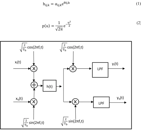
transmitter and receiver. The pdf of such a statistical model follows a Rayleigh distribution as seen in equation 2 [5-7, 14]. Figure 1 presents the functional block diagram of the system.
h , α , e , (1)
p u 1
√2πe
(2)
Figure 1 - System Model representing from baseband transmission to baseband reception Here xi(t) and xq(t) are the in-phase and quadrature components of the baseband transmit signal and yi(t) and yq(t) are the baseband received signals. Equation 3 and equation 4 present the linear model to represent the system
y ,
y , hh ,, hh ,, x ,
x , nn ,, (3)
Y HX N (4)
X is a set of transmit signal vectors in the signal space defined by a set of basis functions. Y is the corresponding set of received signal vectors.
Noise at the receiver is modeled by an NR x 1 column vector whose elements are zero-mean, i.i.d. complex Gaussian random variables with identical variances (power)
cos(2πfct) sin(2πfct) yq(t) xq(t) sin(2πfct) LPF yi(t) xi(t) cos(2πfct) LPF h(t)
EQUALIZATION
The effect of Inter Symbol Interference (ISI) in multipath time –varying dispersive channel is more severe than noise associated with the system. One method to abate this ISI is by implementing equalization or channel inversion at the receiver. Effectively the equalizers are used to decouple the multiple sub-streams in the received sequence. The process of equalization involves realization of a filter w such that . In this work a zero forcing equalizer is formulated based on a minimum error criterion and a MMSE equalizer based on minimum mean square error criterion. A generalized expression for these equalizers that can be used for any NT x NR MIMO system is presented [3].
ZERO FORCING EQUALIZER
A Zero Forcing equalizer is formulated to render the least square estimate of the transmit signal vector. It is shown that, the Zero Forcing equalizer is the pseudo-inverse of the channel matrix. Hence the zero forcing equalizer is purely a function of the channel state or the channel matrix [2]. W represents the ZF equalizer
min |Y HX| (5)
W H~H H~ (6)
With ZF equalization we NT independent data streams are obtained. The output SNR of nth sub‐ stream (μ derived below
γ , μn
H~H , 1 n N (7)
MINIMUM MEAN SQUARE ERROR EQUALIZER
The Zero Forcing equalizer neglects the effect of noise. A more robust equalizer is proposed based on the Minimum Mean Square Error (MMSE) criterion. The equalizer, W renders an estimate of the transmit signal vector such that the mean square error between them is minimum. In this section a brief derivation of the MMSE equalizer is presented. The MMSE criterion is formulated as shown in equation 8 [2].
The MMSE Equalizer is given as
~ ~ (9)
where . ~ represents the hermitian operation
~ 1
μn ~
(10)
It can be seen that the MMSE equalizer is a function of the channel and the noise variance . If the energy of the transmit signal is considered to be unity equation can be written in terms of SNR as in equation 10
With MMSE equalization NT independent data streams are obtained. The output SNR of nth sub-stream can be derived in a similar method as that applied to ZF equalizer. It is given as is given as γ , presented in equation 11[2]
γ , μn
~ 1
μn
1, 1 n N (11)
MAXIMUM LIKELIHOOD RECEIVER
ML receivers are based on optimal vector decoding and they minimize error probability. ML equalization involves calculation of the Euclidian distance between the estimate and all possible transmitted signals (x) and detection of transmitted signal vector that corresponds to the minimum distance. The complexity of this receiver increases for higher order of modulation schemes.
The design criterion of ML receiver is presented below. The objective of the ML receiver is to minimize the probability of error in decoding the transmitted message that is to minimize
P p x x |y t or to maximize p x x |y t . Signal constellation points have a one-to-one relation with a transmitted message an equivalent condition is to maximize p s sent |y t . Correspondingly the decision regions (Z1,...,ZN) are seen to be the sub-sets of the signal space and are defined as follows [28]
SPINNING OF THE VEHICLE
In this work a case of a spinning body such as a missile is considered as one of the communication entities. Due to the spin there is a change in the relative position of the
transmitter and receiver. Hence the spin can be modeled as a periodic modulation of the channel gain. A ‘sine wave model’ is used to mathematically model the antenna gain. This is presented in figure 2
Figure 2 - Sine wave rotation model
RESULTS AND DISCUSSION
As a first step the performance of the proposed equalizers is evaluated by considering a scenario where the transmitters and receivers are stationary. The performance of MMSE equalizer is better than ZF equalizer by nearly 3 dB. The results shown in figure 3 are within one dB of previously established results [1-4]
Figure 3 - Performance of ZF and MMSE for a stationary case
Parameters associated with the sine wave model a – maximum swing in the relative antenna gain b – gain offset
Φ – Angular separation between the antennas T – Time period of rotation
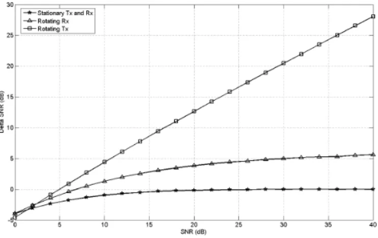
Figure 6 Performance at a/b = 1 and phi = 180 A comparative study of performance of equalizers in these cases is presented based on equation 7 and equation 11 the output SNR of the output streams from the equalizer for cases of stationary transmitter and stationary receiver, rotating transmitter and stationary receiver and rotating receiver and stationary transmitter is obtained. Figure 4 presents the trend of difference between SNRs of the output streams with ZF and MMSE equalizers δ with a/b set to unity. For the stationary case δ saturates to zero. A case of rotating receiver is seen to have similar behavior. However for a case of a rotating transmitter δ increases with increase in SNR.
Figure 4 Difference between SNRs of the output streams with ZF and MMSE equalizers It is seen that the behavior of equalizers for the case where the spinning aero-vehicle is the receiver and the base station is the transmitter follows a trend similar to a case of stationary transmitter and receiver. Therefore it is expected that the MMSE equalizer would perform better than ZF equalizer with their BER performance curves being parallel to each other. In case of spinning aero-vehicle being the transmitter and the base station being the receiver the trend deviates from the stationary case. In this scenario the δ increases with increase in SNR at the transmitter. A general loss of performance in the two cases of spinning antennas is expected due to loss of power that is transmitted in undesired directions. This loss is more pronounced when the antennas are highly directive. Figure 5 and 6 summarize the results discussed in this section.
Figure 5 Performance at a/b = 1 and phi = 180
The behavior ZF and MMSE equalizer in a case of full-duplex communication is studied with one of the communication entities being a spinning aero vehicle. The performance is dictated by the SNR of the output streams from the equalizers. Based on these observations a few important design optimizations are proposed
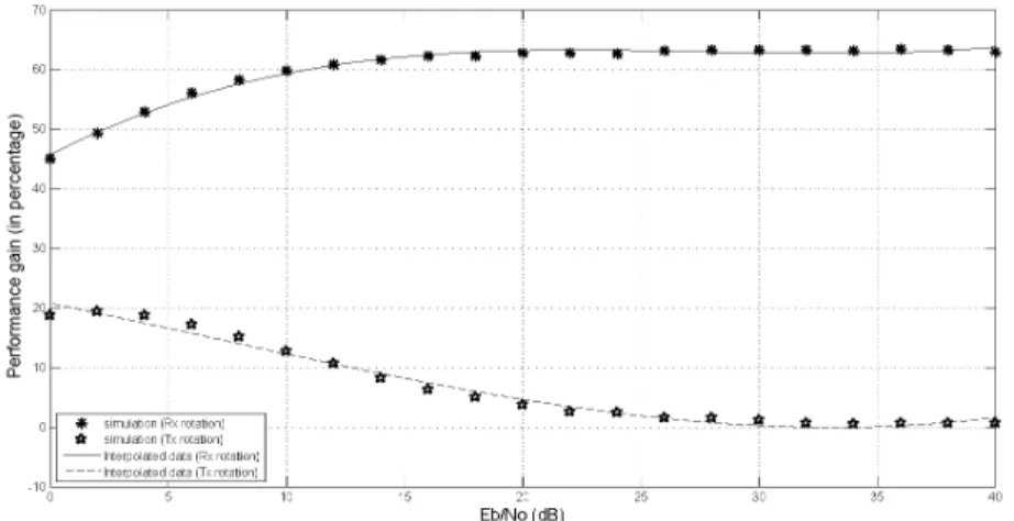
Figure 7 Performance gain in MMSE equalizer
Figure 7 illustrates the performance gain of MMSE equalizer in the cases of rotating Rx and stationary Tx and rotating Tx and stationary Rx. This experiment was conducted with a/b set to unity. It is seen that there is no significant gain in performance with use of MMSE equalizer for a case of rotating transmitter. From Figure 9 it is seen that for a case of rotating receiver MMSE is significantly better than ZF equalizer. However for a case of rotating transmitter the performance of both equalizers closely follow each other. Therefore at the ground station ZF equalizer can be deployed without any loss of performance. This is useful since with ZF equalizer the knowledge of noise statistics is not required.
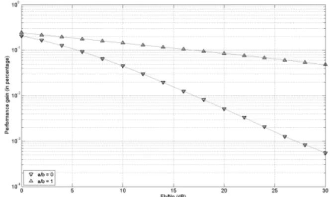
It is seen as the directivity of the antenna increases, the performance drops even though the transmitted power is maintained at the same value. When a/b ratio approaches unity the performance is almost independent of SNR. It is seen that at higher SNR the system is more sensitive to increase in directivity of the antennas. These results are summarized in figure 9 and 8 for the cases of rotating receiver and rotating transmitter respectively. The improved receiver architecture proposed in the previous section is considered in this analysis. Consequently the behavior of MMSE equalizer is studied for a case of rotating transmitters and the performance of ZF equalizer is studied for a case of rotating receiver.
It is seen that angular separation of π radians on the rotating aero-vehicle is most suitable to achieve maximum performance. At this configuration, when the rotating body behaves as a transmitter the performance of ZF equalizer tends closer towards the MMSE equalizer thereby allowing optimization at the transmitter and receiver ends
CONCLUSION
In this paper ZF and MMSE equalizers based on a BLAST architecture has been formulated for a 2x2 MIMO system. A theoretical framework to predict the performance of the equalizers is proposed and verified. The model is checked for correctness by verifying its performance for a static case. Further, the performance is studied for a case in which one of the communication entities is mounted on a spinning vehicle. The effect of directivity and angular placement of antennas is studied. It is seen that the BER increases with increase in directivity of the antenna. Also in such a case the performance of MMSE equalizer closely follows ZF equalizer. Hence, for systems with highly directive antennas a ZF equalizer can replace MMSE. Also with increase in antenna directivity the MIMO systems are less sensitive to SNR. Hence with our observations we suggest that for a/b set to unity lower SNRs can be preferred. It is also proved that antenna placed diametrically opposite on a rotating body is the best solution. Based on the simulation results new design optimizations are proposed. The proposed model is seen to have reduced complexity and computation, smart choice of transmits power and optimal placement of antennas on the spinning vehicle. In the background of the challenging conditions that demand robust solutions for effective communication this work can be seen to be a relevant contribution in the field of aerospace telemetry
Figure 8 Effect of directivity of antennas for a case of rotating receiver Figure 9 Effect of directivity of antennas
BIBLIOGRAPHY
[1] Gupta B. and Saini D.S., “BER performance improvement in MIMO systems using various equalization techniques,” 2012 2nd IEEE International Conference on Parallel Distributed and Grid Computing (PDGC), pp. 190- 194, 2012.
[2] Yi Jiang, Mahesh K. Varanasi and Jian Li, “Performance Analysis of ZF and MMSE Equalizers for MIMO Systems: An In-Depth Study of the High SNR Regime,” IEEE Transactions on Information Theory, Volume 57, Issue 4, pp. 2008 – 2026, 2011
[3] Sammuel Jalali, “Wireless Channel Equalization in Digital Communication Systems,” CGU Theses & Dissertations, Claremont Graduate University, 2012
[4] Sarkar, S., Rahman, M.S., “Bit error rate improvement for QPSK modulation technique in a MIMO Rayleigh fading channel by maximum likelihood equalization,” 2012 7th International Conference on Electrical & Computer Engineering (ICECE), pp. 169 – 173, 2012
[5] Symon Haykin and Michael Moher, Communication Systems, 5th ed. Wiley, John & Sons,
2009
[6] David Tse and Pramod Vishwanath, Fundamentals of Wireless Communication, Cambridge
University press, May 26, 2005
[7] Rodger Ziemer and Roger Peterson, Introduction to Digital Communication, 2nd ed. Prentice
Hall, August 19, 2000
[8] A. J. Paulraj, D. A. Gore, R. U. Nabar, and H. Boelcskei, “An overview of MIMO
communications – A key to gigabit wireless,” Proceedings of the IEEE, vol. 92, no. 2, pp. 198– 218, Feb. 2004.
[9] S. Loyka and F. Gagnon, “Performance analysis of the V-BLAST algorithm: An analytical approach,” IEEE Transaction on Wireless Communication, vol. 3, no. 4, pp. 1326–1337, July 2004.
[10] H. Zhu, Z. Lei, and F. P. S. Chin, “An improved square-root algorithm for BLAST,” IEEE Signal Processing Letter., vol. 11, no. 9, pp. 772–775, Sept. 2004.
[11] N. Boubaker, K. B. Letaief, and R. D. Murch, “Performance of BLAST over frequency-selective wireless communication channels,” IEEE Transaction on Communication, vol. 50, no. 2, pp. 196–199, Feb. 2002.
[13] Andrea Goldsmith, Wireless Communications, Cambridge University Press (August 8,