Wireless-G Access
Point
COPYRIGHT & TRADEMARKS
Specifications are subject to change without notice. Copyright © 2002 Linksys, All Rights Reserved. Instant Wireless, Linksys, and the Linksys logo are registered trademarks of Linksys Group, Inc. Microsoft, Windows, and the Windows logo are registered trade-marks of Microsoft Corporation. All other tradetrade-marks and brand names are the proper-ty of their respective proprietors.
LIMITED WARRANTY
Linksys guarantees that every Instant Wireless Wireless-G Access Point will be free from physical defects in material and workmanship for one year from the date of purchase, when used within the limits set forth in the Specifications section of this User Guide. If the product proves defective during this warranty period, go to the Linksys website at www.linksys.com for complete Return Merchandise Authorization (RMA) assistance. You can also call Linksys Technical Support in order to obtain a RMA Number. BE SURE TO HAVE YOUR PROOF OF PURCHASE AND A BARCODE FROM THE PRODUCT’S PACK-AGING ON HAND WHEN CALLING. RETURN REQUESTS CANNOT BE PROCESSED WITHOUT PROOF OF PURCHASE. When returning a product, mark the RMA Number clearly on the outside of the package and include a copy of your original proof of pur-chase. All customers located outside of the United States of America and Canada shall be held responsible for shipping and handling charges.
IN NO EVENT SHALL LINKSYS'S LIABILITY EXCEED THE PRICE PAID FOR THE PROD-UCT FROM DIRECT, INDIRECT, SPECIAL, INCIDENTAL, OR CONSEQUENTIAL DAM-AGES RESULTING FROM THE USE OF THE PRODUCT, ITS ACCOMPANYING SOFT-WARE, OR ITS DOCUMENTATION. LINKSYS OFFERS NO REFUNDS FOR ITS PROD-UCTS. Linksys makes no warranty or representation, expressed, implied, or statutory, with respect to its products or the contents or use of this documentation and all accom-panying software, and specifically disclaims its quality, performance, merchantability, or fitness for any particular purpose. Linksys reserves the right to revise or update its prod-ucts, software, or documentation without obligation to notify any individual or entity. Please direct all inquiries to:
Linksys P.O. Box 18558, Irvine, CA 92623. SAFETY AND REGULATORY NOTICES FCC STATEMENT
The Instant Wireless Wireless-G Access Point has been tested and found to comply with the specifications for a Class B digital device, pursuant to Part 15 of the FCC Rules. Operation is subject to the following two conditions:
(1) This device may not cause harmful interference, and
(2) This device must accept any interference received, including interference that may cause undesired operation.
These limits are designed to provide reasonable protection against harmful interference in a residential installation. This equipment generates, uses, and can radiate radio fre-quency energy and, if not installed and used according to the instructions, may cause harmful interference to radio communications. However, there is no guarantee that inter-ference will not occur in a particular installation. If this equipment does cause harmful interference to radio or television reception, which is found by turning the equipment off and on, the user is encouraged to try to correct the interference by one or more of the following measures:
• Reorient or relocate the receiving antenna
• Increase the separation between the equipment or devices • Connect the equipment to an outlet other than the receiver's
• Consult a dealer or an experienced radio/TV technician for assistance
FCC Caution: Any change or modification to the product not expressly approved by Linksys could void the user's authority to operate the device.
FCC Caution: Operation within the 5150 to 5250GHz band is restricted to indoor use only. FCC RF Radiation Exposure Statement
To comply with the FCC and ANSI C95.1 RF exposure limits, the antenna(s) for this device must comply with the following:
• Access points with 2.4 GHz or 5 GHz integrated antenna must operate with a sepa-ration distance of at least 20 cm from all persons using the cable provided and must not be co-located or operating in conjunction with any other antenna or transmitter. End-users must be provided with specific operations for satisfying RF exposure compli-ance.
Note: Dual antennas used for diversity operation are not considered co-located. Canadian Department of Communications Industry Canada (IC) Notice This Class B digital apparatus complies with Canadian ICES-003 and RSS-210. Cet appareil numérique de la classe B est conforme à la norme NMB-003 et CNR-210 du Canada.
"To prevent radio interference to the licensed service, this device is intended to be oper-ated indoors and away from windows to provide maximum shielding. Equipment (or its transmit antenna) that is installed outdoors is subject to licensing."
" Pour empêcher que cet appareil cause du brouillage au service faisant l'objet d'une licence, il doit être utilisé à l'intérieur et devrait être placé loin des fenêtres afin de fournir un écran de blindage maximal. Si le matériel (ou son antenne d'émission) est installé à l'extérieur, il doit faire l'objet d'une licence. "
EC DECLARATION OF CONFORMITY (EUROPE)
Linksys Group declares that the Instant Wireless®Series products included in the Instant
Wireless®Series conform to the specifications listed below, following the provisions of the
European R&TTE directive 1999/5/EC, EMC directive 89/336/EEC, and Low Voltage directive 73/23/EEC:
For 54 Mbps, 5 GHz access points with 40 mW radios, the following standards were applied:
• ETS 301 489-1, 301 489-17 General EMC requirements for Radio equipment. • EN 609 50 Safety
• ETS 301-893 Technical requirements for Radio equipment.
Caution: The frequencies used by 802.11a wireless LAN devices are not yet harmonized within the European community, 802.11a products are designed for use only in specific countries, and are not allowed to be operated in countries other than those of designat-ed use. Contact local Authority for procdesignat-edure to follow.
Caution: This equipment is intended to be used in all EU and EFTA countries. Outdoor use may be restricted to certain frequencies and/or may require a license for operation. Contact local Authority for procedure to follow.
Table of Contents
Chapter 1: Introduction 1
The Instant Wireless Wireless-G Access Point 1
Features 1
Chapter 2: Planning Your Wireless Network 2
Network Topology 2
Roaming 2
Chapter 3: Getting to Know the Wireless-G
Access Point 3
The Wireless-G Access Point’s Back Panel 3
The Wireless-G Access Point’s Front Panel 4
Chapter 4: Connecting the Wireless-G
Access Point 5
Chapter 5: Setting Up the Wireless-G
Access Point 6
Chapter 6: Configuring the Wireless-G
Access Point 14
The Setup Tab 14
The Password Tab 18
The AP Mode Tab 19
The Status Tab 21
The Log Tab 23
The Help Tab 24
The Filter Tab 25
The Advanced Wireless Tab 27
The SNMP Tab 29
Appendix A: Troubleshooting 30
Frequently Asked Questions 30
Note: Combinations of power levels and antennas resulting in a radiated power level of above 100 mW equivalent isotropic radiated power (EIRP) are considered as not com-pliant with the above mentioned directive and are not allowed for use within the European community and countries that have adopted the European R&TTE directive 1999/5/EC and/or the CEPT recommendation Rec 70.03.
For more details on legal combinations of power levels and antennas, contact Linksys Corporate Compliance.
• Linksys Group vakuuttaa täten että Instant Wireless Wireless-G Access Point tyyp-pinen laite on direktiivin 1999/5/EY, direktiivin 89/336/EEC ja direktiivin 73/23/EEC oleellisten vaatimusten ja sitä koskevien näiden direktiivien muiden ehtojen mukainen.
• Linksys Group déclare que la Instant Wireless Wireless-G Access Point est conforme aux conditions essentielles et aux dispositions relatives à la directive 1999/5/EC, la directive 89/336/EEC, et à la directive 73/23/EEC.
• Belgique B L'utilisation en extérieur est autorisé sur le canal 11 (2462 MHz), 12 (2467 MHz), et 13 (2472 MHz). Dans le cas d'une utilisation privée, à l'extérieur d'un bâti-ment, au-dessus d'un espace public, aucun enregistrement n'est nécessaire pour une distance de moins de 300m. Pour une distance supérieure à 300m un enreg-istrement auprès de l'IBPT est requise. Pour une utilisation publique à l'extérieur de bâtiments, une licence de l'IBPT est requise. Pour les enregistrements et licences, veuillez contacter l'IBPT.
• France F:
2.4 GHz Bande : les canaux 10, 11, 12, 13 (2457, 2462, 2467, et 2472 MHz respec-tivement) sont complétement libres d'utilisation en France (en utilisation intérieur). Pour ce qui est des autres canaux, ils peuvent être soumis à autorisation selon le départment. L'utilisation en extérieur est soumis à autorisation préalable et très restreint.
5 GHz Bande: Conformément aux décisions de la CEPT, l'utilisation des fréquences de la bande 5150 MHz - 5350 MHz est autorisée à l'intérieur des bâtiments avec une puissance maximale de 200 mW, et interdite en extérieur. La bande 5470 MHz - 5725 MHz n'est pas ouverte aujourd'hui.
Vous pouvez contacter l'Autorité de Régulation des Télécommunications (http://www.art-telecom.fr) pour de plus amples renseignements.
2.4 GHz Band: only channels 10, 11, 12, 13 (2457, 2462, 2467, and 2472 MHz respectively) may be used freely in France for indoor use. License required for out-door installations.
5 GHz Band: frequencies in the 5150 MHz - 5350 MHz band may be used indoor with maximum power of 200 mW. Their use is forbidden outdoors. The 5470 MHz -5725 MHz band is not currently open.
Please contact ART (http://www.art-telecom.fr) for procedure to follow.
• Deutschland D: Anmeldung im Outdoor-Bereich notwending, aber nicht genehmi-gungspflichtig. Bitte mit Händler die Vorgehensweise abstimmen.
• Germany D: License required for outdoor installations. Check with reseller for proce-dure to follow.
• Italia I: E' necessaria la concessione ministeriale anche per l'uso interno. Verificare con i rivenditori la procedura da seguire. L'uso per installazione in esterni non e' per-messa.
• Italy I: License required for indoor use. Use with outdoor installations not allowed. • The Netherlands NL License required for outdoor installations. Check with reseller for
procedure to follow.
• Nederlands NL Licentie verplicht voor gebruik met buitenantennes. Neem contact op met verkoper voor juiste procedure.
Instant Wireless® Series Wireless-G Access Point
Chapter 1: Introduction
The Instant Wireless Wireless-G Access Point
Wireless-G is the upcoming 54Mbps wireless networking standard that's almost five times faster than the widely deployed Wireless-B (802.11b) prod-ucts found in homes, businesses, and public wireless hotspots around the coun-try — but since they share the same 2.4GHz radio band, Wireless-G devices can also work with existing 11Mbps Wireless-B equipment.
The Linksys G Access Point lets you connect G or Wireless-B devices to the network. Since both standards are built in, you can protect your investment in existing 802.11b infrastructure, and migrate your network clients to the new screaming fast Wireless-G standard as your needs grow.
To protect your data and privacy, the Wireless-G Access Point can encrypt all wireless transmissions. The MAC Address filter lets you decide exactly who has access to your wireless network. Configuration is a snap with the web browser-based configuration utility.
Future-proof your wireless network with the Linksys Wireless-G Access Point. You'll enjoy Wireless-B connectivity today, and be prepared for a high-speed Wireless-G tomorrow.
• Set up a high-speed Wireless-G (draft 802.11g) network in your home or office
• Data rates up to 54Mbps -- 5 times faster than Wireless-B (802.11b) • Also interoperates with Wireless-B networks (at 11Mbps)
• Advanced wireless security with 128-bit WEP encryption and MAC filter-ing
• Free Technical Support—24 Hours a Day, 7 Days a Week, Toll-Free U.S. Calls
• 1-Year Limited Warranty
Features
Appendix B: Setting Up the TCP/IP and
IPX Protocols 35
Setting Up TCP/IP in Windows 35
TCP/IP Setup for Windows 98 and Millennium 36
IPX Setup for Windows 98 and Millennium 36
TCP/IP Setup for Windows NT 4.0 37
IPX Setup for Windows NT 4.0 37
TCP/IP Setup for Windows 2000 38
IPX Setup for Windows 2000 38
TCP/IP Setup for Windows XP 39
Appendix C: Glossary 40
Appendix D: Specifications 48
Environmental 49
Appendix E: Warranty Information 50
Chapter 3: Getting to Know the
Wireless-G Access Point
The Access Point’s ports, where a network cable is connected, are located on the Access Point’s back panel.
Reset Button There are two ways to Reset the Access Point’s factory defaults. Either press the Reset Button using a small, pointed object like a ball-point pen, for approximately ten seconds, or restore the defaults from the password tab in the Access Point’s Web-Based Utility.
LAN This LAN (Local Area Network) port connects to Ethernet network devices, such as a hub, switch, or router.
Power The Power port is where you will connect the power adapter.
The Wireless-G Access Point’s Back Panel
Figure 3-1
Important:Resetting the Access Point will erase all of your settings (WEP Encryption, Wireless and LAN settings, etc.) and replace them with the factory defaults. Do not reset the Access Point if you want to retain these settings
Chapter 2: Planning Your
Wireless Network
A wireless LAN is a group of computers, each equipped with one Instant Wireless Series adapter. Computers in a wireless LAN must be configured to share the same radio channel.
The Instant Wireless Series adapters provide access to a wired LAN for wire-less workstations. An integrated wirewire-less and wired LAN is called an infra-structure configuration. A group of Instant Wireless Series adapter users and an Instant Wireless Wireless-G Access Point compose a Basic Service Set (BSS). Each Instant Wireless Series adapter PC in a BSS can talk to any com-puter in a wired LAN infrastructure via the Wireless-G Access Point.
An infrastructure configuration extends the accessibility of an Instant Wireless Series adapter PC to a wired LAN, and doubles the effective wireless trans-mission range for two Instant Wireless Series adapter PCs. Since the Wireless-G Access Point is able to forward data within its BSS, the effective transmis-sion range in an infrastructure LAN is doubled.
Infrastructure mode also supports roaming capabilities for mobile users. More than one BSS can be configured as an Extended Service Set (ESS). This con-tinuous network allows users to roam freely within an ESS. All PCs equipped with an Instant Wireless Series adapter within one ESS must be configured with the same ESS ID and use the same radio channel.
Before enabling an ESS with roaming capability, choosing a feasible radio channel and optimum Wireless-G Access Point position is recommended. Proper Access Point positioning combined with a clear radio signal will great-ly enhance performance.
Roaming
Wireless-G Access Point
Chapter 4: Connecting the
Wireless-G Access Point
1. Locate an optimum location for the Access Point.The best place for the Access Point is usually at the center of your wireless network, with line of sight to all of your mobile stations.
2. Fix the direction of the antenna.Try to place it in a position which can best cover your wireless network. Normally, the higher you place the anten-na, the better the performance will be. The antenna’s position enhances the receiving sensitivity.
3. Connect a standard Ethernet network cable to the Access Point.Then, connect the other end of the Ethernet cable to a switch or hub. The Access Point will then be connected to your 10/100 Network.
4. Connect the AC Power Adapter to the Access Point’s Power port and plug the other end into an electrical outlet.Only use the power adapter supplied with the Access Point. Use of a different adapter may result in product damage.
Now that the hardware installation is complete, proceed to Chapter 5: Setting Up the Wireless-G Access Pointfor directions on how to set up the Access Point.
Instant Wireless® Series
Note:In order for all other wireless devices to communicate with the Access Point, those devices must be operating in
Infrastructure Mode. If any wireless devices are configured in
Ad Hoc Mode, they will notbe recognized by the Access Point.
T
Power Green. The Power LED lights up when the Access Point is powered on.
Diag Red. The DiagLED indicates the Access Point’s self-diagnosis mode during boot-up and restart. It will turn off upon com-pleting the diagnosis. If this LED stays on for an abnormally long period of time, refer to the Troubleshooting Appendix.
WLAN Act Green. If the WLAN’s ActLED is flickering, the Access Point is actively sending or receiving data to or from one of the devices on the network.
WLAN Link Green. The WLAN’s LinkLED lights whenever there is a suc-cessful wireless connection.
LAN Act/LinkGreen. The LAN’s LINK LED serves two purposes. If the LED is continuously lit, the Access Point is successfully con-nected to a device through the LAN port. If the LED is flick-ering, it is an indication of any network activity.
LAN Full/Col Green. The LAN’s Full/ColLED also serves two purposes. When this LED is continuously lit, the connection made through the corresponding port is running in Full Duplex mode. A flickering LED indicates that the connection is expe-riencing collisions. Infrequent collisions are normal. If this LED blinks too often, there may be a problem with your con-nection. Refer to the Troubleshooting Appendix if you think there is a problem.
LAN 100 Orange. The LAN’s 100 LED indicates when a successful 100Mbps connection is made through the LAN port.
The Wireless-G Access Point’s Front Panel
3. The following screen, shown in Figure 5-2, displays how the Access Point is configured in this Setup Wizard. Optimally, you should perform this setup through a PC on your wired network. Click the Nextbutton to con-tinue or Exitto exit the Setup Wizard.
Chapter 5: Setting Up the
Wireless-G Access Point
Now that you’ve connected the Access Point to your wired network, you are ready to begin setting it up. This Setup Wizard will take you through all the steps necessary to configure the Access Point.
1. Insert the Setup Wizard CD into your PC’s CD-ROM drive. Your PC must be on your wired network to set up the Access Point.
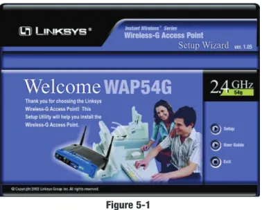
2. The Setup Wizard should run automatically, and the screen in Figure 5-1 should appear on your monitor. If it does not, start the Setup Wizard man-ually by clicking the Startbutton, selecting Run, and typing d:\setup.exe
(where “D” is your PC’s CD-ROM drive). Click the Setupbutton to con-tinue this Setup Wizard. Clicking the User Guidebutton opened this User Guide. To exit this Setup Wizard, click the Exitbutton.
Figure 5-2 Figure 5-1 Have You:Connected the Access Point to a hub, switch or router
on your wired network as shown in Chapter 4: Connecting the Wireless-G Access Point? The Access Point can only be set up through your wired network.
Note: While the Access Point has been designed to work correctly right out of the box, setting it up on a wireless computer will require you to use the Linksys default settings. These settings can then be changed with the Setup Wizard or Web-based Browser Utility.
Wireless-G Access Point
6. As shown in Figure 5-5, the IP Settings screen will appear next. Enter an IP Address, Subnet Mask, and enter a unique access point name for the Access Point appropriate to your network. Then, click the Nextbutton to continue or Backto return to the previous page.
• IP Address. This IP address must be unique to your network. (The default IP address is 192.168.1.245.)
• Subnet Mask. The Access Point’s Subnet Mask must be the same as your Ethernet network.
• AP Name.Assign a name to the Access Point. Unique, memorable names are helpful, especially if you are employing multiple access points on the same network.
Instant Wireless® Series
4. The next screen to appear, shown in Figure 5-3, will display a list of access points on your network along with the status information for each access point. If this is the only access point on your network, it will be the only one displayed. If there are more than one displayed, select the Access Point by clicking on it and click the Yesbutton to continue or Noto exit the Setup Wizard.
5. You will be asked to sign on to the Access Point you’ve selected, as shown in Figure 5-4. Enter the Password you’ve assigned. If none has been assigned, enter the default password:admin. Then, click the OK button. (This password can be changed from the Web-based Utility’s Password tab.)
Figure 5-3
Figure 5-4
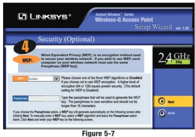
8. The Security Settings screen (Figure 5-7) will appear next. From this screen, you will set the Wired Equivalent Privacy (WEP) encryption for your wireless network. Select a WEP configuration method and a passphrase. Click the Nextbutton to continue or Backto return to the pre-vious page.
• WEP (Disable/64-bit (10 hex digits)/128-bit (26 hex digits)). In order to utilize WEP encryption, select the WEP setting from the pull-down menu, 64-bit (10 hex digits)or 128-bit (26 hex digits). If you do not wish to utilize WEP encryption, make sure Disabled is selected. The Access Point’s WEP encryption is unique to Linksys and may conflict with other vendors’ WEP encryption.
• Passphrase. Instead of manually entering WEP keys, you can enter a Passphrase. This Passphrase is used to generate one or more WEP keys. It is case-sensitive and should not be longer than 16 alphanumeric char-acters. (The Passphrase function is compatible with Linksys wireless products only. If you want to communicate with non-Linksys wireless products, you will need to enter your WEP keys manually on the non-Linksys wireless products.)
Figure 5-7
7. As shown in Figure 5-6, the Basic Settings screen will appear. Enter your wireless network’s SSID and select the channel at which the network broad-casts its wireless signal. Then, click the Nextbutton to continue or Backto return to the previous page.
• SSID.The SSID is the unique name shared among all points in a wireless network. The SSID must be identical for all points in the wireless net-work. It is case sensitive, must not exceed 32 characters, and may be any keyboard character. Make sure this setting is the same for all points in your wireless network.
• Channel.Select the appropriate channel from the list provided to corre-spond with your network settings, between 1 and 11 (in North America). All points in your wireless network must use the same channel in order to function correctly. All points in your wireless network must use the same channel in order to function correctly.
Figure 5-6
Note:The passphrase function doesn’t work when mixing other manufacturers’ products into your wireless network. Linksys prod-ucts should always be used for optimum functionality. If using another company’s wireless product, set the WEP key manually.
Note:WEP encryption should be used when communicating over a wireless network. Wireless transmissions are unprotected and WEP encryption helps to make your wireless network safer to use.
Instant Wireless® Series Wireless-G Access Point
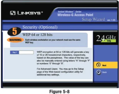
9. The second Security Settingsscreen, shown in Figure 5-8, shows the WEP key. If you entered a passphrase, then the Key 1field will display the auto-matically generated WEP key. If you did not enter a passphrase, then enter a WEP key in the Key 1field. Each point in your wireless network must use the same WEP key for the network to function properly. Click the Next but-ton to continue or Back to return to the previous page.
• Key 1. WEP keys enable you to create an encryption scheme for wire-less networks. If the WEP key hasn’t been automatically generated, then manually enter a set of values. (Do not leave the field blank, and do not enter all zeroes. These are not valid key values.) If you are using 64-bit WEP encryption, then each key must consist of exactly 10 hexadecimal characters in length. If you are using 128-bit WEP encryption, then each key must consist of exactly 26 hexadecimal characters in length. Valid hexadecimal characters are “0”-“9” and “A”-“F”.
Figure 5-8
Note:WEP encryption should be used whenever communicating over a wireless network. Wireless transmissions, by their very nature, are unprotected and WEP encryption helps to close this hole in security and make your wireless network safer to use.
10. The next screen (Figure 5-9) will allow you to review your settings. If these settings are correct, click the Yesbutton to save these settings. If there are any problems with the settings, click the Nobutton to exit the Setup Wizard.
11. At this point, the configuration performed with the Setup Wizard is com-plete, as shown in Figure 5-10. To configure any other access points in your network, you can run this Setup Wizard again. Click the Exitbutton to exit the Setup Wizard.
Figure 5-10 Figure 5-9
LAN
• MAC Address. The MAC Address of the LAN interface is displayed here.
• Configuration Type. Select Static IP Addressif your ISP provided you with the IP Address, Subnet Mask, and default Gateway address or Select
Automatic Configuration - DHCPif your ISP assigns IP addresses via DHCP.
• IP Address. The IP address must be unique to your network. We suggest you use the default IP address of 192.168.1.245. This is a private IP address, so there is no need to purchase a separate IP address from your service provider. Verify the address and click the Applybutton to save changes.
• Subnet Mask. The Access Point’s Subnet Mask (or IP Mask) must be the same as your Ethernet network. Verify this is correct and click the Apply
button to set it.
• Gateway. If you have assigned a static IP address to the Access Point, then enter the IP address of your network’s Gateway, such as a router, in the
Gatewayfield. If your network does not have a Gateway, then leave this field blank.
Figure 6-2
Chapter 6: Configuring the
Wireless-G Access Point
The Access Point has been designed to be functional right out of the box, with the default settings in the Setup Wizard. However, if you’d like to change these settings, the Access Point can be configured through your web browser with the Web-Based Utility. This chapter explains how to configure the Access Point in this manner.
Open your web browser and type the IP Address you entered in the Setup Wizard (the default IP address is 192.168.1.245). Press the Enterkey and the following screen, shown in Figure 6-1, will appear. Leave the User Name
field blank. The first time you open the Web-based Utility, use the default password admin. You can set a new password on the
Passwordscreen shown in Figure 6-5.
The first screen that appears, shown in Figure 6-2, is the Setuptab. This allows you to change the Access Point’s general settings. Change these settings as described here, and click the Applybutton to apply your changes or Cancelto cancel your changes. If you require online help, click the Helpbutton.
• Firmware Version.This displays the current version of the Access Point’s firmware. Firmware should only be upgraded if you experience problems with the Access Point and can be upgraded from the Helptab.
• AP Name. You may assign any name to the Access Point. Unique, memo-rable names are helpful, especially if you are employing multiple access points on the same network. Verify this is the name you wish to use and click the Applybutton to set it.
Figure 6-1
The Setup Tab
Note: The Access Point is designed to function properly after using the Setup Wizard. This chapter is provided solely for those who wish to perform more advanced configuration or monitoring.
Wireless-G Access Point Instant Wireless® Series
Wireless
• MAC Address. The MAC Address of the 2.4 GHz, Draft 802.11g interface is displayed here.
• Mode. Select Mixedand both Wireless-G and Wireless-B computers will be allowed on the network, but the speed will be reduced. Select G-Only for maximum speed, but no Wireless-B users will be allowed on the network.
• SSID. The SSID is the unique name shared among all points in a wireless network. The SSID must be identical for all points in the wireless network. It is case-sensitive and must not exceed 32 alphanumeric characters, which may be any keyboard character. Make sure this setting is the same for all points in your wireless network. For added security, Linksys recommends that you change the SSID from the default linksysto a unique name.
• SSID Broadcast.Allows the SSID to be broadcast on your network. You may want to enable this function while configuring your network, but make sure that you disable it when you are finished. With this enabled, someone could easily obtain the SSID information with site survey software and gain unau-thorized access to your network. Click Enableto broadcast. Click Disable to increase network security and prevent the SSID from being seen on networked PCs.
• Channel. Select the appropriate channel from the list provided to corre-spond with your network settings, between 1 and 11 (in North America). All points in your wireless network must use the same channel in order to func-tion correctly.
• WEP. The WEP (Wired Equivalent Privacy) Encryption method is set to
Disableby default. To enable WEP, click the Enableradio button, and then click the Edit WEP Settingsbutton to configure the WEP settings.
SETTING WEP ENCRYPTION:
If the Disable radio button is selected and you click the Edit
WEP Settings button, then the screen shown in Figure 6-3 will appear. Click theOKbutton to enable WEP encryption or Cancel
to return to the Setupscreen. Set WEP Encryption through the
Web-based Utility by clicking the Edit WEP Settings button on the Setup
screen as shown in Figure 6-2.
Figure 6-3
This will open the WEP Keysscreen, Figure 6-4. From this screen, you can select the type of WEP encryption to use and set the Passphrase for that encryption.
• Default Transmit Key. Select the number of the key you want to use for the Access Point to send data. Use the same key for the receiver of data.
• WEP encryption. From the pull-down menu, select 64-bit 10 hex digitsor
128-bit 26 hex digitsfor WEP encryption. Higher encryption levels offer higher levels of security, but may decrease the network speed.
• Passphrase.This will allow you to set a passphrase used to generate a WEP key. The passphrase is case sensitive and must be 16 or less alphanumeric characters. Click the Generatebutton to create the WEP key(s).
• Keys 1-4. WEP key fields allow you to manually enter the WEP encryp-tion keys. Use hexadecimal characters, which are the letters “A” through “F” and the numbers “0” through “9”. Do not leave a key field blank and do not enter all zeroes. For 64-bit WEP encryption, each key must consist of exactly 10 hexadeciamal characters. For 128-bit WEP encryption, each key must consist of exactly 26 hexadecimal characters.
Click the Applybutton to apply your changes, or click Cancelto cancel your most recent change.
Figure 6-4
Important:Always remember that each point in your wireless net-work MUST use the same WEP encryption method and encryption key, or else your wireless network will not function properly.
SETTING THE AP MODE:
The Access Point offers two modes of operation for the 2.4 GHz, draft 802.11g: Access Point and Wireless Bridge. For all bridging modes, make sure the chan-nel, SSID, and WEP key settings are the same.
• Access Point -The operational mode is set to Access Point by default. This connects your wireless PCs to a wired network. In most cases, no change is necessary.
• Wireless Bridge - If you are trying to make a wireless connection between two or more wired networks, as shown in Figure 6-7, select Wireless Bridge. This mode connects two physically separated wired networks with two access points.
To configure a Wireless Bridge environment, click Wireless Bridge and enter the LAN MAC address of the remote access point in the Remote Wireless Bridge’s LAN MAC Addressesfield. The remote access point also needs to be set up as a Wireless Bridge.
Note:All devices on each wired network must be connected through a hub or switch.
Click the Apply button to apply your changes or Cancel to cancel your changes. If you require online help, click the Helpbutton.
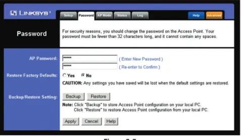
The Passwordtab, shown in Figure 6-5, allows you to change the Access Point’s password and restore factory defaults.
• AP Password.Changing the password for the Access Point is as easy as typing the password into the AP Passwordfield. Then, type it again into the second field to confirm.
• Restore Factory Defaults.To restore the Access Point’s factory default set-tings, click the Yes button beside Restore Factory Defaults. You will lose any settings you have saved.
• Backup/Restore Setting. To back up your Access Point configuration, click the Backup button. To restore your Access Point configuration, click the Restore button.
Click the Apply button to apply your changes or Cancel to cancel your changes. If you require online help, click the Helpbutton.
The Password Tab
Important:Restoring the Access Point’s factory defaults will erase all of your settings (WEP Encryption, Wireless and LAN settings, etc.), replacing them with the factory defaults. Do not reset the Access Point if you want to retain these settings
Figure 6-5
Figure 6-6
Wireless-G Access Point
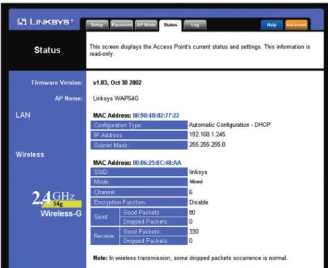
The Statustab, shown in Figure 6-8, will display current information on the Access Point, its settings, and its performance.
• Firmware Version.The current version of the Access Point’s firmware is displayed. Firmware should only be upgraded from the Help tab if you experience problems with the Access Point.
• AP Name. This displays the name you assigned to the Access Point.
Figure 6-8
The Status Tab
Instant Wireless® Series
Note: In Wireless Bridge mode, the Access Point can ONLY be accessed by another access point in Wireless Bridge mode. In order for your other wireless devices to access the Access Point, you must reset it to Access Point mode. The two modes are mutually exclusive.
To view a log of the Access Point’s activity, select the Logtab, shown in Figure 6-9.
Log. To enable permanent logging activity, click the Enable radio button beside Log. The default setting for this function is Disable.
If you have chosen to monitor the Access Point’s traffic, then you can designate a PC that will receive permanent log files periodically. In the Send Log tofield, enter the IP address of this PC. To view these permanent logs, you must use Logviewer software, which can be downloaded free of charge from
www.linksys.com.
To see a temporary log of the Access Point’s most recent activities, click the
View Logbutton.
Click the Apply button to apply your changes or Cancel to cancel your changes. If you require online help, click the Helpbutton.
The Log Tab
Figure 6-9
LAN
• MAC Address. The MAC Address of the LAN interface is displayed here.
• Configuration Type. This displays how the Access Point is assigned an IP address, either Automatic Configuration - DHCP, if assigned by DHCP server, or Static IP Address and its IP Address, Subnet Mask, and Default Gateway address, if assigned by Static IP Address server.
• IP Address. This IP address is the unique IP address of the Access Point.
• Subnet Mask. The Access Point’s Subnet Mask (also known as an IP Mask), matches the Subnet Mask of your Ethernet network.
Wireless
• MAC Address. The MAC Address of the LAN interface is displayed here.
• SSID.The unique name shared among all points in your wireless network is displayed here.
• Mode.The Access Point’s mode is displayed here.
• Channel.The wireless channel shared by all wireless devices connected to this Access Point is displayed here.
• Encryption Function. The encryption method you chose in the Setup Wizard or changed from the Setuptab of this Web-based Utility is displayed here.
• Send and Receive. The Sendand Receivefields display the number of suc-cessful or dropped packets that have been sent or received. Some packet loss is normal in wireless networking.
Wireless-G Access Point Instant Wireless® Series
To upgrade the Access Point’s firmware:
1. Download the firmware upgrade file from the Linksys website. 2. Extract the firmware upgrade file.
3. Click the Upgrade Firmwarebutton on the Helpscreen.
4. Enter the location of the firmware upgrade file in the File Pathfield, or click the Browsebutton to find the firmware upgrade file.
5. Double-click the firmware upgrade file.
6. Click the Upgradebutton, and follow the on-screen instructions. Click the Cancelbutton to cancel the firmware upgrade.
To access the Filtertab, first click the Advancedtab. The Filtertab, shown in Figure 6-12, allows you to control which computers may or may not commu-nicate with the Access Point—depending on their MAC addresses.
To enable filtering of computers by their MAC Addresses, click the Enable
radio button. To disable this feature, click the default Disableradio button. Next, determine if the Access Point will Preventor Permitaccess to the PCs you will specify. If you want to block specific PCs from communicating with with the Access Point, click the radio button next to Prevent PCs listed below from accessing the wireless network.If you want to allow specific PCs from communicating with with the Access Point, click the radio button next to
Permit PCs listed below from accessing the wireless network.
The Filter Tab
For help on the various tabs in this Web-based Utility, along with upgrading the Access Point’s firmware and viewing this User Guide, click the Help tab, shown in Figure 6-10.
The help files for the various tabs in this Web-based Utility are listed by tab name on the lefthand side of the screen.
Click the Linksys Website link to connect to the Linksys home page for Knowledgebase help files and information about other Linksys products, pro-vided you have an active Internet connection.
For an Online manual in PDF format, click that text link. The User Guide will appear in Adobe pdf format. If you do not have the Adobe PDF Reader installed on your computer, click the Adobe Websitelink or go to the Setup Wizard CD-ROM to download this software. (To access the Adobe website, you will need an active Internet connection.) To download from the CD-ROM, click the Start but-ton and select Run. Type D:\Acrobat(if “D” is the letter of your CD-ROM drive). New firmware versions are posted at www.linksys.comand can be downloaded for free. If the Access Point is not experiencing difficulties, then there is no need to download a more recent firmware version, unless that version has a new feature that you want to use. Loading new firmware does not always enhance the speed or quality of your Internet connection.
The Help Tab
Figure 6-10
Figure 6-11
Note:When you upgrade the Access Point’s firmware, you may lose the Access Point’s current configuration settings.
Before making any changes to the Advanced Wirelesstab, shown in Figure 6-13, please check your wireless settings on your other systems, because these changes will alter the effectiveness of the Access Point. In most cases, these wireless settings do not need to be changed.
• Authentication Type.The default is set toAuto, where it auto-detects for
Shared Keyor Open System. Shared Key is when both the sender and the recipient share a WEP key for authentication. Open Key is when the sender and the recipient do not share a WEP key for authentication. All points on your network must use the same authentication type.
• Transmission Rates.The default setting is Auto. The range is from 1 to 54Mbps. The rate of data transmission should be set depending on the speed of your wireless network. You can select from a range of transmission speeds, or you can keep the default setting, Auto, to have the Access Point automatically use the fastest possible data rate and enable the Auto-Fallback feature. Auto-Fallback will negotiate the best possible connection speed between the Access Point and a wireless client.
Figure 6-13
Above the MAC Address fields, there is a pull-down menu. This pull-down menu is for selecting the number of computers on your wireless network. For computers one through ten on your wireless network, 1~20 is selected by default. If you have more than twenty computers on your wireless network, use this pull-down menu to select 21~40.
Then, type the MAC Address(es) you wish to filter in the MAC Addressfields. Do not use colons when entering the digits. Use a xxxxxxxxxxxx format with the x’s representing the actual characters of the MAC address. If you want to clear the MAC addresses you entered, click the Clearbutton .
When you’ve completed making any changes on this tab, click the Apply but-ton to save those changes or Cancel to cancel your changes. For more infor-mation on this tab, click the Helpbutton.
Figure 6-12
Wireless-G Access Point Instant Wireless® Series
The SNMP screen allows you to customize the Simple Network Management
Protocol (SNMP) settings. SNMP is a popular network monitoring and man-agement protocol.
The Identification settings let you designate the Contact, Device Name, and Location information for the Access Point. The SNMP Community settings allow names to be assigned to any SNMP communities that have been set up in the network. You can define two different SNMP communities, with the default names being Public and Private.
• SNMP. To enable the SNMP support feature, select Enable. Otherwise, select Disable.
• Identification. In the Contact field, enter contact information for the Access Point. In the Device Namefield, enter the name of the Access Point. In the Locationfield, specify the area or location where the Access Point resides.
• SNMP Community.You may change the name from its default, Public. Enter a new name in the Public field. Then configure the community's access as either Read-Only or Read-Write.You may change the name from its default, Private. Enter a new name in the Privatefield. Then configure the community's access as either Read-Only or Read-Write.
When you’ve completed making any changes on this tab, click the Apply but-ton to save those changes or Cancelto cancel your changes. For more infor-mation on this tab, you can click the Helpbutton.
• Beacon Interval. This value indicates the frequency interval of the beacon. The default value is 100. Enter a value between 20 and 1000 milliseconds. The Beacon Interval value indicates the frequency interval of the beacon. A beacon is a packet broadcast by the Access Point to synchronize the wire-less network.
• RTS Threshold. This value should remain at its default setting of 2346. Should you encounter inconsistent data flow, only minor reductions are rec-ommended.
• Fragmentation Threshold. This value specifies the maximum size for a packet before data is fragmented into multiple packets. It should remain at its default setting of 2346. A smaller setting means smaller packets, which will create more packets for each transmission. Only minor reductions of this value are recommended.
• DTIM Interval. The default value is 3. This value, between 1 and 255 mil-liseconds, indicates the interval of the Delivery Traffic Indication Message (DTIM). A DTIM field is a countdown field informing clients of the next window for listening to broadcast and multicast messages. When the Access Point has buffered broadcast or multicast messages for associated clients, it sends the next DTIM with a DTIM Interval value. Access Point Clients hear the beacons and awaken to receive the broadcast and multicast mes-sages.
When you’ve completed making any changes on this tab, click the Apply but-ton to save those changes or Cancelto cancel your changes. For more infor-mation on this tab, you can click the Helpbutton.
The SNMP Tab
What is Roaming?
Roaming is the ability of a portable computer user to communicate continu-ously while moving freely throughout an area greater than that covered by a single Access Point. Before using the roaming function, the workstation must make sure that it is the same channel number as the Access Point of the dedi-cated coverage area.
To achieve true seamless connectivity, the wireless LAN must incorporate a number of different functions. Each node and Access Point, for example, must always acknowledge receipt of each message. Each node must maintain contact with the wireless network even when not actually transmitting data. Achieving these functions simultaneously requires a dynamic RF networking technology that links Access Points and nodes. In such a system, the user’s end node under-takes a search for the best possible access to the system. First, it evaluates such factors as signal strength and quality, as well as the message load currently being carried by each Access Point and the distance of each Access Point to the wired backbone. Based on that information, the node next selects the right Access Point and registers its address. Communications between end node and host computer can then be transmitted up and down the backbone.
As the user moves on, the end node’s RF transmitter regularly checks the sys-tem to determine whether it is in touch with the original Access Point or whether it should seek a new one. When a node no longer receives acknowl-edgment from its original Access Point, it undertakes a new search. Upon find-ing a new Access Point, it then re-registers, and the communication process continues.
What is BSS ID?
A specific Ad-hoc LAN is called a Basic Service Set (BSS). Computers in a BSS must be configured with the same BSS ID.
What is ESSID?
An Infrastructure configuration could also support roaming capability for mobile workers. More than one BSS can be configured as an Extended Service Set (ESS). Users within an ESS could roam freely between BSSs while main-taining a continuous connection to the wireless network stations and Access Points.
What is ISM band?
The FCC and their counterparts outside of the U.S. have set aside bandwidth for unlicensed use in the ISM (Industrial, Scientific and Medical) band. Spectrum in the vicinity of 2.4 GHz, in particular, is being made available
Appendix A: Troubleshooting
This chapter provides solutions to problems usually encountered during the installation and operation of the Access Point. Read the description below to solve your problems. If you can’t find an answer here, check the Linksys web-site at www.linksys.com.
Can the Access Point act as my DHCP Server?
No. The Access Point is nothing more than a wireless hub, and as such cannot be configured to handle DHCP capabilities.
Can I run an application from a remote computer over the wireless net-work?
This will depend on whether or not the application is designed to be used over a network. Consult the application’s user guide to determine if it supports oper-ation over a network.
Can I play multiplayer games with other users of the wireless network?
Yes, as long as the game supports multiple players over a LAN (local area net-work). Refer to the game’s user guide for more information.
What IEEE 802.11b features are supported?
The product supports the following IEEE 802.11 functions: • CSMA/CA plus Acknowledge protocol
• Multi-Channel Roaming • Automatic Rate Selection • RTS/CTS feature
• Fragmentation • Power Management
What is Ad-hoc?
An Ad-hoc wireless LAN is a group of computers, each with a WLAN adapter, connected as an independent wireless LAN. An Ad-hoc wireless LAN is appli-cable at a departmental scale for a branch or SOHO operation.
What is Infrastructure?
An integrated wireless and wired LAN is called an Infrastructure configura-tion. Infrastructure is applicable to enterprise scale for wireless access to a cen-tral database, or wireless application for mobile workers.
Wireless-G Access Point
What is WEP?
WEP is Wired Equivalent Privacy, a data privacy mechanism based on a 40-bit shared-key algorithm, as described in the IEEE 802.11 standard.
What is a MAC Address?
The Media Access Control (MAC) address is a unique number assigned by the manufacturer to any Ethernet networking device, such as a network adapter, that allows the network to identify it at the hardware level. For all practical pur-poses, this number is usually permanent. Unlike IP addresses, which can change every time a computer logs on to the network, the MAC address of a device stays the same, making it a valuable identifier for the network.
How do I avoid interference?
Using multiple Access Points on the same channel and in close proximity to one another will generate interference. When employing multiple Access Points, be sure to operate each one on a different channel (frequency).
How do I reset the Access Point?
Press the Resetbutton on the back of the Access Point for about ten seconds. This will reset the unit to its default settings.
How do I resolve issues with signal loss?
There is no way to know the exact range of your wireless network without test-ing. Every obstacle placed between an Access Point and wireless PC will cre-ate signal loss. Leaded glass, metal, concrete floors, wcre-ater and walls will inhib-it the signal and reduce range. Start winhib-ith your Access Point and your wireless PC in the same room and move it away in small increments to determine the maximum range in your environment.
You may also try using different channels, as this may eliminate interference affecting only one channel. Also, due to FCC regulations, more power may be transmitted, using 802.11a, on channels 52, 56, 60 and 64, than on the lower channels. Lastly, check the Advanced tab of the Web-Based Utility and make sure that FULL is selected in the Transmission Rate field.
Does the Access Point function as a firewall?
No. The Access Point is only a bridge from wired Ethernet to wireless clients.
I have excellent signal strength, but I cannot see my network.
WEP is probably enabled on the Access Point, but not on your wireless adapter (or vice versa). Verify that the same WEP Keys and levels (64 or 128 ) are being used on all nodes on your wireless network.
Instant Wireless® Series
worldwide. This presents a truly revolutionary opportunity to place convenient high speed wireless capabilities in the hands of users around the globe.
What is Spread Spectrum?
Spread Spectrum technology is a wideband radio frequency technique devel-oped by the military for use in reliable, secure, mission-critical communica-tions systems. It is designed to trade off bandwidth efficiency for reliability, integrity, and security. In other words, more bandwidth is consumed than in the case of narrowband transmission, but the trade-off produces a signal that is, in effect, louder and thus easier to detect, provided that the receiver knows the parameters of the spread-spectrum signal being broadcast. If a receiver is not tuned to the right frequency, a spread-spectrum signal looks like background noise. There are two main alternatives, Direct Sequence Spread Spectrum (DSSS) and Frequency Hopping Spread Spectrum (FHSS).
What is DSSS? What is FHSS? And what are their differences?
Frequency Hopping Spread Spectrum (FHSS) uses a narrowband carrier that changes frequency in a pattern that is known to both transmitter and receiver. Properly synchronized, the net effect is to maintain a single logical channel. To an unintended receiver, FHSS appears to be short-duration impulse noise. Direct Sequence Spread Spectrum (DSSS) generates a redundant bit pattern for each bit to be transmitted. This bit pattern is called a chip (or chipping code). The longer the chip, the greater the probability that the original data can be recovered. Even if one or more bits in the chip are damaged during transmis-sion, statistical techniques embedded in the radio can recover the original data without the need for retransmission. To an unintended receiver, DSSS appears as low power wideband noise and is rejected (ignored) by most narrowband receivers.
Would the information be intercepted while transmitting on air?
WLAN features two-fold protection in security. On the hardware side, as with Direct Sequence Spread Spectrum technology, it has the inherent security fea-ture of scrambling. On the software side, the WLAN series offers the encryp-tion funcencryp-tion (WEP) to enhance security and access control. Users can set it up depending upon their needs.
Can Instant WirelessTMproducts support file and printer sharing?
Instant WirelessTMproducts perform the same function as LAN products.
Therefore, Instant WirelessTMproducts can work with Netware, Windows
Appendix B: Setting Up the TCP/IP and
IPX Protocols
Before a computer can communicate with the Access Point, it must be config-ured with the TCP/IP protocol. If you know how to set up TCP/IP on your com-puters, do so now. Otherwise, use the guidelines below to help get TCP/IP installed on all of the computers that need to communicate with the Access Point. If you are unable to successfully install TCP/IP on one or more comput-ers after following the directions, contact the manufacturer of your computcomput-ers' network operating system for further assistance. Check with your network administrator for your TCP/IP settings.
The directions below provide general guidelines for coming up with IP address-es and subnet masks. Check with your network administrator to see if you need to use specific IP addresses or DHCP settings.
First, each computer on the network will require an IP address, which is a series of numbers, separated by periods, identifying the PC on the network. To make things simple, you should use the following numbering scheme:
192.168.1.X
In this example, X is a unique, arbitrarily assigned number from 1 to 254. Each computer must have its own unique X number. Note: Never use 0, 250 or 255 for X. These numbers are reserved by TCP/IP for other uses.
For example, if you have three computers, you could number them as follows: 192.168.1.17
192.168.1.44 192.168.1.126
In this case, 17, 44, and 126 are arbitrary numbers between 1 and 254. Each computer will also require a subnet mask, which is a numerical “filter” that tells a computer what kinds of TCP/IP data packets to accept. If you’re not sure which mask to use, the following mask is recommended:
255.255.255.0
What is the maximum number of users the Access Point facilitates?
No more than 65, but this depends on the volume of data and may be less if many users create a large amount of network traffic.
How many channels/frequencies are available with the Access Point?
Using 802.11b or draft 802.11g, there are eleven available channels, ranging from 1 to 11.
Wireless-G Access Point
1. Click the Start button, select Settings, and open the Control Panel. Inside the Control Panel, double-click the Network icon.
2. When the Networkwindow appears, click the Protocolstab. Then, click the Addbutton.
3. Find the TCP/IP protocolin the Select Network Protocolfield. Click it once and then click the OKbutton.
4. When asked if you want to use DHCP, choose No.
5. If asked to supply your Windows NT CD, do so. NT will copy the neces-sary files to your system. You may have to switch between the Access Point’s Setup CD and the NT CD.
6. When TCP/IP appears in the Network Protocols window, click the
Bindingstab. Windows will store your new bindings. 7. Click the Protocolstab. Then, selectTCP/IP.
8. Click the Propertiesbutton. Select the type of network adapter you have from the Adapters box and select Specify an IP Address.
9. Enter the computer’s IP Address and Subnet Mask. Check with your net-work administrator for your settings.
10. Enter your Default Gateway if you have one.
11. When you finish, click the OKbutton. If NT asks about WINS, ignore it. 12. When the Networkwindow reappears, click the Closebutton. Restart your
computer when prompted. TCP/IP has now been successfully installed.
1. Click the Startbutton, select Settings, and open the Control Panel. Inside the Control Panel, double-click the Network icon.
Instant Wireless® Series
The following instructions are provided as examples for reference only. For complete instructions on installing and troubleshooting TCP/IP and IPX, con-sult your Windows operating system documentation.
1. Click the Startbutton, select Settings, and open the Control Panel. Inside the Control Panel, double-click the Networkicon.
2. If the TCP/IP Protocolis listed for your network adapter, go to step five. Otherwise, click the Addbutton.
3. When the Component Typewindow appears, select Protocoland click the
Addbutton.
4. Select Microsoft in the Manufacturers list and choose TCP/IP in the Network Protocols list. Then, click the OKbutton.
5. When the Network window reappears, click TCP/IP. Then, click the
Propertiesbutton.
6. Select Specify an IP Address.
7. Enter an IP Address for the computer, along with a Subnet Mask. Click the
OKbutton. If you do not have these values, consult your network adminis-trator.
8. When the Network window reappears, click the OK button. Restart your machine. TCP/IP has now been successfully installed.
1. Click the Startbutton, select Settings, and open the Control Panel. Inside the Control Panel, double-click the Networkicon.
2. If the TCP/IP Protocolis listed for your network adapter, go to step four. Otherwise, click the Addbutton.
3. When the Component Typewindow appears, select Protocoland click the
Addbutton.
4. Select Microsoftin the Manufacturers list and choose IPX/SPX protocol
in the Network Protocols list. Then, click the OKbutton.
TCP/IP Setup for Windows NT 4.0
N
Noottee:: a Default Gateway is not required. Check with your network administrator.
IPX Setup for Windows NT 4.0 TCP/IP Setup for Windows 98 and Millennium
4. Select NWLink IPX/SPX/NetBIOS Compatible Transport Protocol
from the list and click the OKbutton.
5. When the Networkwindow reappears, click the OKbutton. Restart your computer. NWLink IPX/SPX/NetBIOS Compatible Transport Protocol has now been successfully installed.
1. Click the Startbutton and open the Control Panel. 2. Double click the Network and Internet Connectionsicon. 3. Double click the Network Connectionsicon.
4. Right click the Local Area Connectionicon and select Properties. 5. If the TCP/IP Protocolis listed for your network adapter, go to step five.
Otherwise, click the Installbutton.
6. When the Component Typewindow appears, select Protocol, and click the
Addbutton.
7. Select Internet Protocol (TCP/IP) from the list and click the OKbutton. 8. When the Local Area Connection Properties window reappears, select
TCP/IP, and click the Propertiesbutton. 9. Select Use the following IP Address.
10. Enter an IP Address for the computer, along with a Subnet Mask and Default Gateway. Then, click the OKbutton. If you do not have these val-ues, consult your network administrator.
11. When the Local Area Connection Properties window reappears, click the
OKbutton. TCP/IP has now been successfully installed.. 2. When the Network window appears, click the Protocolstab. Then, click
the Addbutton.
3. Find the IPX/SPX protocolin the Select Network Protocolfield. Click it once and click the OKbutton.
1. At the Windows 2000 desktop, right click My Network Places and select
Properties. Then, right click Local Area Connection. Choose Properties. 2. If the TCP/IP Protocolis listed for your network adapter, go to step five.
Otherwise, click the Installbutton.
3. When the Component Typewindow appears, select Protocol, and click the
Addbutton.
4. Select Internet Protocol (TCP/IP) from the list and click the OKbutton. 5. When the Local Area Connection Properties window reappears, select
TCP/IP, and click the Propertiesbutton. 6. Select Use the following IP Address.
7. Enter an IP Address for the computer, along with a Subnet Mask and Default Gateway. Then, click the OKbutton. If you do not have these val-ues, consult your network administrator.
8. When the Local Area Connection Properties window reappears, click the
OKbutton. TCP/IP has now been successfully installed.
1. At the Windows 2000 desktop, right click My Network Places. Then right click Local Area Connection. Choose Properties.
2. If the NWLink IPX/SPX/NetBIOS Compatible Transport Protocol is listed for your network adapter, click the Cancel button. Otherwise, click the
Installbutton.
3. When the Component Type window appears, select Protocoland click the
Installbutton.
TCP/IP Setup for Windows XP TCP/IP Setup for Windows 2000
Wireless-G Access Point Instant Wireless® Series
Browser- A browser is an application program that provides a way to look at and interact with all the information on the World Wide Web or PC. The word "browser" seems to have originated prior to the Web as a generic term for user interfaces that let you browse text files online.
BSS(Basic Service Set) - A group of wireless Network PC Card users and an Access Point.
Buffer - A buffer is a shared or assigned memory area used by hardware devices or program processes that operate at different speeds or with different sets of priorities. The buffer allows each device or process to operate without being held up by the other. In order for a buffer to be effective, the size of the buffer and the algorithms for moving data into and out of the buffer need to be considered by the buffer designer. Like a cache, a buffer is a "midpoint holding place" but exists not so much to accelerate the speed of an activity as to sup-port the coordination of separate activities.
CSMA/CA (Carrier Sense Multiple Access/Collision Avoidance) - In local area networking, this is the CSMA technique that combines slotted time-divi-sion multiplexing with carrier sense multiple access/collitime-divi-sion detection (CSMA/CD) to avoid having collisions occur a second time. This works best if the time allocated is short compared to packet length and if the number of sit-uations is small.
CSMA/CD(Carrier Sense Multiple Access/Collision Detection) - The LAN access method used in Ethernet. When a device wants to gain access to the net-work, it checks to see if the network is quiet (senses the carrier). If it is not, it waits a random amount of time before retrying. If the network is quiet and two devices access the line at exactly the same time, their signals collide. When the collision is detected, they both back off and each wait a random amount of time before retrying.
CTS(ClearTo Send) - An RS-232 signal sent from the receiving station to the transmitting station that indicates it is ready to accept data.
Database- A database is a collection of data that is organized so that its con-tents can easily be accessed, managed, and updated.
DHCP(Dynamic Host Configuration Protocol) - A protocol that lets network administrators manage centrally and automate the assignment of Internet Protocol (IP) addresses in an organization's network. Using the Internet's set of protocol (TCP/IP), each machine that can connect to the Internet needs a
Appendix C: Glossary
802.11b - One of the IEEE standards for wireless networking hardware. Products that adhere to a specific IEEE standard will work with each other, even if they are manufactured by different companies. The 802.11b standard specifies a maximum data transfer rate of 11Mbps, an operating frequency of 2.4GHz, and WEP encryption for security. 802.11b networks are also referred to as Wi-Fi networks.
802.11g- A proposed, but as yet unratified extension of the IEEE 802.11 stan-dard for wireless networking hardware. The draft 802.11g specifications used by Linksys specify a maximum data transfer rate of 54Mbps using OFDM modulation, an operating frequency of 2.4GHz, backward compatibility with IEEE 802.11b devices and WEP encryption for security.
Adapter- Printed circuit board that plugs into a PC to add to capabilities or connectivity to a PC. In a networked environment, a network interface card is the typical adapter that allows the PC or server to connect to the intranet and/or Internet.
Ad-hoc Network- An ad-hoc network is a wireless network or other small net-work in which some of the netnet-work devices are part of the netnet-work only for the duration of a communications session while in some close proximity to the rest of the network.
Backbone- The part of a network that connects most of the systems and net-works together and handles the most data.
Bandwidth - The transmission capacity of a given facility, in terms of how much data the facility can transmit in a fixed amount of time; expressed in bits per second (bps).
Beacon Interval- A beacon is a packet broadcast by the Access Point to keep the network synchronized. A beacon includes the wireless LAN service area, the AP address, the Broadcast destination addresses, a time stamp, Delivery Traffic Indicator Maps, and the Traffic Indicator Message (TIM).
Bit- A binary digit. The value - 0 or 1-used in the binary numbering system. Also, the smallest form of data.