HIGH PERFORMANCE SEQUENTIAL
EXECUTION IN FINE-GRAIN MULTICORE
PROCESSORS VIA CORE AGGREGATION
A Dissertation
Presented to the Faculty of the Graduate School of Cornell University
in Partial Fulfillment of the Requirements for the Degree of Doctor of Philosophy
by
Meyrem Kırman February 2010
c
2010 Meyrem Kırman ALL RIGHTS RESERVED
HIGH PERFORMANCE SEQUENTIAL EXECUTION IN FINE-GRAIN MULTICORE PROCESSORS VIA CORE AGGREGATION
Meyrem Kırman, Ph.D. Cornell University 2010
This dissertation presents core fusion, a reconfigurable chip multiprocessor (CMP) architecture where groups of fundamentally independent cores can dy-namically morph into a larger CPU, or they can be used as distinct processing el-ements, as needed at run time by applications. Core fusion improves sequential-code performance and thus gracefully accommodates software diversity in fu-ture’s highly-parallel CMPs. It provides a single execution model across all con-figurations, requires no additional programming effort or specialized compiler support, maintains ISA compatibility, and leverages mature micro-architecture technology.
We first present an effective approach to dynamically fuse multiple narrow-issue out-of-order cores into a more powerful out-of-order execution engine. The use of out-of-order base cores provides the design with valuable opportu-nities for latency hiding.
Next, we present a second set of mechanisms to dynamically fuse multiple in-order cores into a more powerful out-of-order execution engine. In-order cores are extremely power-efficient and simple, and they help maximize core count, which is ideal for exploiting thread-level parallelism (TLP). However, sequential-code performance is significantly degraded. Enabling core fusion on such substrates proves to be very effective in boosting performance, and only with relatively small hardware overhead.
BIOGRAPHICAL SKETCH
Meyrem Kırman graduated with B.S. degrees in Control and Computer Engi-neering and Electronics and Communication EngiEngi-neering in 2002 and 2003, re-spectively, from Istanbul Technical University (ITU), Turkey. In Fall 2003, she started her M.S./Ph.D. study in Electrical and Computer Engineering at Cornell University. Along the way, she earned her M.S. degree in 2007. Her research in-terests included checkpointed processor architectures, reconfigurable processor architectures, on-chip optical interconnects and memory-system design for chip multiprocessors.
ACKNOWLEDGEMENTS
I would like to express my gratitude to Prof. Jos´e F. Mart´ınez, my adviser, for all his contributions to my academic and personal development, and for provid-ing a great workprovid-ing environment. His continuous guidprovid-ing and support, always constructive critiques, and high standards made my graduate study a valuable and enriching one. I thank him for his patient and devoted efforts for develop-ing our presentation, writdevelop-ing and communication skills. Discussions with him have always been very inspiring and instructive. I also thank him for creat-ing a workcreat-ing environment which I feel great pleasure to work in, as well as providing numerous opportunities to us for attending conferences and other professional activities.
I am greatly indebted to my sister Nevin Kırman. Without her support, it would be difficult to successfully complete this work. She is continuous source of motivation and joy. I deeply thank her for always being with me in my good and difficult times.
I would like to thank Prof. Rajit Manohar and Prof. David Albonesi for being a part of my committee, their useful feedback, and their contributions to the Computer Systems Laboratory (CSL) and its warm environment.
I also thank my group members and other CSL members for fruitful collab-orations, numerous discussions, and the good time spent together. I feel lucky to be a part of such friendly and stimulating research environment.
Finally, I am deeply thankful to my family for their continuous support and motivation, comfort and encouragement.
TABLE OF CONTENTS
Biographical Sketch . . . iii
Dedication . . . iv
Acknowledgements . . . v
Table of Contents . . . vi
List of Tables . . . viii
List of Figures . . . ix
1 Introduction* 1 2 Core Fusion Based on Out-of-order Cores* 6 2.1 Architecture . . . 7
2.1.1 Front-end . . . 8
2.1.2 Back-end . . . 14
2.2 Dynamic Reconfiguration . . . 18
3 Evaluating Fusion of Out-of-order Cores* 19 3.1 Experimental Setup . . . 19
3.2 Hardware Overhead . . . 21
3.3 Core-Fusion Performance . . . 23
3.4 Performance Analysis . . . 24
4 Core Fusion Based on In-order Cores 29 4.1 Base In-order Core . . . 30
4.2 Architecture . . . 32
4.2.1 Distributed Program State . . . 33
4.2.2 Distributed Fetch . . . 34
4.2.3 Satisfying Register Dependences . . . 35
4.2.4 Checkpoint Allocation, Commit, and Recovery . . . 40
4.2.5 Register Recycling . . . 42
4.2.6 Hardware Support for Register Renaming, Checkpoint-ing, and Release . . . 44
4.2.7 Satisfying Memory Dependences . . . 45
4.2.8 SMU Organization . . . 48
4.2.9 Performance Enhancements . . . 49
5 Evaluating Fusion of In-order Cores 55 5.1 Experimental Setup . . . 55
5.2 Area and Delay Estimations . . . 57
5.3 Base-Core Performance . . . 59
5.4 In-order Core Fusion Performance . . . 60
5.5 Performance Analysis . . . 62
5.5.1 Lookahead Execution . . . 62
5.5.3 Register Replication . . . 67
5.6 Comparison to Out-of-Order Cores . . . 67
6 Banking Memory Operations in In-order Core Fusion 72 6.1 Mechanism for Memory-Operation Banking . . . 73
6.2 Hardware Support for Bank Prediction . . . 75
6.2.1 Choice of Bank Predictor . . . 76
6.2.2 Speculative Update . . . 77
6.2.3 In-order Update . . . 78
6.2.4 Reusing Verified Bank Predictor Updates . . . 78
6.3 Evaluation of Memory-Operation Banking . . . 79
6.3.1 Hardware Overhead Estimation . . . 79
6.3.2 Performance Evaluation . . . 80
6.4 Dynamic Policy for Memory-Operation Handling . . . 82
7 Related Work* 86 7.1 Reconfigurable Architectures . . . 86
7.2 Clustered Architectures . . . 87
7.3 Scalable Issue-Queue Designs . . . 91
7.4 Other Related Work . . . 92
8 Conclusions 94
LIST OF TABLES
3.1 Two-issue out-of-order core parameters . . . 20
3.2 Memory-system parameters for out-of-order cores . . . 20
5.1 In-order core and memory-system parameters . . . 56
5.2 Parameters specific to in-order-core fusion. . . 57
5.3 Area overhead of in-order-core fusion . . . 57
5.4 Out-of-order core parameters . . . 68
7.1 Comparison of out-of-order core fusion to recent proposals for clustered processors. . . 88
LIST OF FIGURES
2.1 Conceptual floorplan of an eight-core CMP with core fusion ca-pability . . . 8 2.2 Configuration-oblivious indexing in branch predictor and BTB . 10 2.3 Rename pipeline and illustrative example of steering
manage-ment unit organization in out-of-order core fusion . . . 12 2.4 Simplified diagram of distributed ROB in out-of-order core fusion 15 3.1 Speedup of order core fusion relative to two-issue
out-of-order core on SPECINT . . . 23 3.2 Speedup of order core fusion relative to two-issue
out-of-order core on SPECFP . . . 23 3.3 Distribution of fetch cycles in out-of-order core fusion on SPECINT 25 3.4 Distribution of fetch cycles in out-of-order core fusion on SPECFP 26 3.5 Sensitivity of out-of-order core fusion performance to various
parameters on SPECINT . . . 27 3.6 Sensitivity of out-of-order core fusion performance to various
parameters on SPECFP . . . 27 4.1 Pipeline of the base in-order core . . . 31 4.2 In-order-core fusion support . . . 33 4.3 Copy-instruction flow through the source and destination cores . 39 4.4 Local rename table, checkpointing, and register recycling
sup-port in a core . . . 44 4.5 Lookahead execution (LE) support . . . 50 5.1 Base in-order core’s execution-time breakdown . . . 60 5.2 Speedup of in-order-core fusion over in-order core on SPEC . . . 61 5.3 Impact of lookahead execution on performance of in-order-core
fusion . . . 62 5.4 Issue-time breakdown of fused in-order cores when running
SPEC applications . . . 63 5.5 Speedup of a base in-order core enhanced with lookahead
exe-cution relative to the base core on SPEC . . . 64 5.6 Impact of copy-out queue selection on performance of
in-order-core fusion . . . 66 5.7 Impact of register replication on performance of in-order-core
fu-sion . . . 67 5.8 Speedup of single- and dual-issue out-of-order cores relative to
base in-order core . . . 69 6.1 Bank predictor and interface to the SMU . . . 75 6.2 Speedup of in-order core fusion with different static
6.3 Breakdown of bank predictions by the block-offset predictor based on accuracy and confidence . . . 82 6.4 Speedup of in-order core fusion with dynamic policy for
CHAPTER 1
INTRODUCTION*
Chip multiprocessors (CMPs) hold the prospect of translating Moore’s Law into sustained performance growth by incorporating more and more cores on the die. In the short term, on-chip integration of a modest number of relatively powerful cores may yield high utilization when running multiple sequential workloads. However, sustaining long-term performance scalability calls for power- and performance-efficient, small-footprint core (micro)architectures that maximize raw performance per power and overall throughput. Consequently, harnessing the full potential of future CMPs makes the widespread adoption of parallel programming inevitable. Unfortunately, code parallelization consti-tutes a tedious, time-consuming, and error-prone effort. Significant amount of code, therefore, is anticipated to remain sequential in future’s parallel comput-ing substrates.
Beside the existing legacy sequential applications, difficulties of parallel pro-gramming is likely to result in a dynamic and diverse landscape of software of very different characteristics and in different stages of development: from purely sequential, to highly parallel, and everything in between. Improving re-gions of sequential code, even in highly-parallel applications, is crucial to main-tain scalability, as also stressed by an article revisiting the Amdahl’s Law in the multicore era [23]. In some cases, the problem itself is sequential or hard-to-parallelize in nature. As a result, future highly-parallel CMP substrates have to address sequential codes whose performance will be confined to a small core.
∗c ACM, 2007. Mostly reprinted, with permission, from ”E. Ipek, M. Kırman, N. Kırman,
J. F. Mart´ınez. Core Fusion: Accommodating software diversity in chip multiprocessors. In Intl. Symp. on Computer Architecture (ISCA), pages 186-197, San Diego, CA, Jun. 2007. http://doi.acm.org/10.1145/1250662.1250686”
Asymmetric chip multiprocessors (ACMPs) [3, 31, 32] comprise cores of varying sizes and computational capabilities. The hope is to match the demands of a variety of sequential and parallel software. Still, the particular die compo-sition is set at design time. Ultimately, this may constitute a hurdle to high performance. For example, Balakrishnan et al. [3] find that asymmetry gen-erally hurts parallel application scalability, and renders the applications’ per-formance less predictable, unless relatively sophisticated software changes are introduced. Hence, for example, while an ACMP may deliver increased perfor-mance on sequential codes by placing one large core on the die, it may do so at the expense of parallel performance or programmability.
Instead, we would like a CMP to provide the flexibility to dynamically “syn-thesize” the right composition, based on software demands. In this thesis, we investigate a novel reconfigurable hardware mechanism that we callcore fusion. It is an architectural technique that empowers groups of relatively simple and fundamentally independent CMP cores with the ability to “fuse” into one large CPU on demand to execute sequential code at higher performance. We envision a core fusion CMP as a homogeneous substrate with conventional memory co-herence/consistency support, where groups of cores and their i- and d-caches can be fused at run-time into CPUs that have aggregated fetch, issue, and com-mit width, and aggregated i-cache, d-cache, branch predictors. Our approach promotes single-thread performance in many core CMPs of homogenous sub-strate of simpler and smaller cores by aggressively extracting ILP, improving memory-latency tolerance, and increase memory-level parallelism.
The core-fusion concept has the potential to provide a number of highly de-sirable benefits to CMP design and functionality. Among them:
• Support for software diversity.CMPs may be configured for fine-grain paral-lelism (by providing many lean cores), coarse-grain paralparal-lelism (by fusing many cores into fewer, but more powerful CPUs), sequential code (by exe-cuting on one fused group), and different levels of multiprogramming (by providing as many fused groups as needed, up to capacity). In contrast, for example, Asymmetric CMPs (ACMPs) [3, 31] are “stuck” with the mix chosen at design time, which may compromise performance for parallel codes and/or mismatched multiprogrammed workloads.
• Support for smoother software evolution. Core fusion would naturally sup-port incremental parallelization, by dynamically providing the optimal configuration for sequential and parallel regions of a particular code, e.g., one large fused group during sequential regions, and many small inde-pendent cores during parallel regions.
• Single-design solution. A fusion group is essentially a modular structure comprising several identical cores, plus the core fusion fabric. Core fusion CMPs can be designed by tiling as many such groups as desired. In con-trast, for example, ACMPs require the adoption of at least two processor core designs.
• Optimized for parallel code. Core fusion comprises relatively small and fundamentally independent cores. This provides good isolation across threads in parallel runs, both internally (branch predictor, i- and d-TLB, physical registers, etc.) and at the L1 cache level (i- and d-cache). The core fusion support allows cores to work co-operatively when needed (albeit probably at somewhat lower performance than a large, monolithic pro-cessor). In contrast, techniques like simultaneous multithreading (SMT) take the opposite approach: A large wide-issue core that is optimized for
sequential execution, augmented with support for multiple threads to crease utilization. When executing parallel applications, cross-thread in-terference in SMT designs is an obstacle to high performance. In a software landscape where parallel code is expected to be increasingly more preva-lent, a “bottom-up” approach like core fusion may be preferable. (More-over, SMT support can be added to core fusion’s base cores.)
• Design-bug and hard-fault resilience. A design bug or hard fault in the core fusion hardware need not disable an entire fusion group, as each core may still be able to operate independently. Similarly, a hard fault in one core still allows independent operation of the other fault-free cores, and even smaller-way fusion on the other cores in the fusion group. Bug/hard fault isolation may be significantly more challenging in designs based on large cores.
At the same time, providing CMPs with the ability to “fuse” cores on de-mand presents significant design challenges. Among them:
• Core fusion should not increase software complexity. Specifically, cores should be able to execute programs co-operatively without changing the execution model, and without resorting to custom ISAs or specialized compiler support. This alone would set core fusion apart from other pro-posed reconfigurable architectures, such as TRIPS [52] or Smart Memo-ries [36], and from speculative architectures such as Multiscalar [53].
• Core fusion hardware should work around the fundamentally indepen-dent nature of the base cores. This means providing complexity-effective solutions to collective fetch, rename, execution, cache access and commit,
by leveraging each core’s existing structures without unduly overprovi-sioning or significantly restructuring the base cores.
• Dynamic reconfiguration should be efficient, and each core’s hardware structures should work fundamentally the same way regardless of the con-figuration.
In this thesis, we look at both narrow out-of-order and in-order core sub-strates to build upon when constructing a core-fusion architecture. The choice of base core presents a trade-off to chip designers. An out-of-order core achieves higher sequential-code performance, while an in-order core provides higher power and cost efficiency, and maximizes core count and throughput on CMPs.
In the first part of our thesis, we construct a core-fusion architecture based on dual-issue out-of-order cores. In the second part of the thesis, we construct a core-fusion architecture based on single-issue in-order cores. In both cases, we respect the capabilities of the base cores and try to devise techniques that leverage existing resources and mechanisms.
CHAPTER 2
CORE FUSION BASED ON OUT-OF-ORDER CORES*
In this chapter, we present a detailed description of a complete hardware solution to support dynamic core fusion in CMPs of narrow out-of-order cores. In particular, we describe complexity-effective solutions for collective fetch, re-name, execution, cache access, and commit, that respect the fundamentally in-dependent nature of the base cores. The result is a flexible CMP architecture that can adapt to a diverse collection of software. It does so without requiring higher software complexity, a customized ISA, or specialized compiler support.
In the course of formulating our core-fusion solution, we make the following additional contributions over prior art:
• A reconfigurable, distributed front-end and instruction-cache organiza-tion that can leverage individual cores’ front-end structures to feed an aggressive fused back-end, with minimal over-provisioning of individual front-ends.
• A complexity-effective remote wake-up mechanism that allows operand communication across cores without requiring additional register file ports, wake-up buses, bypass paths, or issue-queue ports.
• A reconfigurable, distributed load/store queue and data cache organiza-tion that (a) leverages the individual cores’ data caches and load/store queues in all configurations; (b) does not cause thread interference in L1 caches when cores run independently; (c) supports conventional
coher-∗c ACM, 2007. Reprinted, with permission, from ”E. Ipek, M. Kırman, N. Kırman, J.
F. Mart´ınez. Core Fusion: Accommodating software diversity in chip multiprocessors. In
Intl. Symp. on Computer Architecture (ISCA), pages 186-197, San Diego, CA, Jun. 2007. http://doi.acm.org/10.1145/1250662.1250686”
ence when running parallel code, generates zero coherence traffic within the fusion group when running sequential code in fused mode, and re-quires minimal changes to each core’s CMP subsystem;(d)guarantees cor-rectness without requiring data cache flushes upon runtime configuration changes; and(e)enforces memory consistency in both modes.
• A reconfigurable, distributed ROB organization that can fully leverage individual cores’ ROBs to seamlessly support fusion, without overprovi-sioning or unnecessarily replicating core ROB structures.
Our evaluation pits core fusion against more traditional CMP architectures, such as fine- and coarse-grain homogeneous cores.
2.1
Architecture
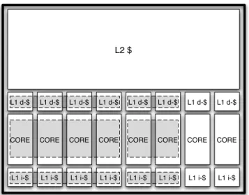
Core fusion builds on top of a substrate comprising identical, relatively efficient two-issue out-of-order cores. A bus connects private L1 i- and d-caches, and provides data coherence. On-chip L2 cache and memory controller reside on the other side of this bus. Cores can execute fully independently if desired. It is also possible to fuse groups of two or four cores to constitute larger cores. Figure 2.1 is an illustrative example of a CMP comprising eight two-issue cores with core fusion capability. The figure shows an (arbitrarily chosen) asymmet-ric configuration comprising one eight-issue, one four-issue, and two two-issue processors.
We now describe in detail the core fusion support. In the discussion, we assume four-way fusion.
CORE L1 i-$ L1 d-$ CORE L1 i-$ L1 d-$ CORE L1 i-$ L1 d-$ CORE L1 i-$ L1 d-$ CORE L1 i-$ L1 d-$ CORE L1 i-$ L1 d-$ CORE L1 i-$ L1 d-$ CORE L1 i-$ L1 d-$ L2 $
Figure 2.1: Conceptual floorplan of an eight-core CMP with core fusion capability. The figure shows a configuration example compris-ing two independent cores, a two-core fused group, and a four-core fused group. The figure is not meant to represent an actual floorplan.
2.1.1
Front-end
Collective Fetch
A small co-ordinating unit called thefetch management unit(FMU) facilitates col-lective fetch. The FMU receives and re-sends relevant fetch information across cores. The latency from a core into the FMU and out to any other core is two cycles (Section 3.1).
Fetch Mechanism and Instruction Cache
Each core fetches two instructions from its own i-cache every cycle, for a to-tal of eight instructions. Fetch is aligned, with core zero generally responsible
for the oldest two instructions. On a taken branch (or misprediction recovery), however, the target may not be aligned with core zero. In that case, lower-order cores skip fetch, and core-zero-aligned fetch resumes on the next cycle.
On an i-cache miss, an eight-word block is delivered (a) to the requesting core if it is operating independently, or(b)distributed across all four cores in a fused configuration to permit collective fetch. To support these two options, we make i-caches reconfigurable along the lines of earlier works [36]. Each i-cache has enough tags to organize its data in two-word subblocks in fused mode.
During collective fetch, i-TLBs are “naturally” replicated as cores miss on their i-TLBs. The FMU can be used to refill all i-TLBs upon a first i-TLB miss by a core. The FMU is used to gang-invalidate i-TLB entries.
Branches and Subroutine Calls
Prediction. Because collective fetch is aligned, each branch instruction always accesses the same branch predictor and BTB. Consequently, the effective branch predictor and BTB capacity is four times as large. To accomplish maximum utilization, these structures are indexed as shown in Figure 2.2 regardless of the configuration. We empirically observe no loss in prediction accuracy when using this “configuration-oblivious” indexing scheme.
Each core can handle up to one branch prediction per cycle. PC redirection (predict-taken, mispredictions) is enabled through the FMU.
Naturally, on a misprediction, misspeculated instructions are squashed in all cores. This is also the case for instructions “overfetched” along the not-taken
Index
Tag (BTB Only)
Byte
t-2
i-1
Figure 2.2: Configuration-oblivious indexing utilized in branch prediction and BTB. In the figure, i bits are used for indexing and t for tagging (tagging only meaningful in the BTB). Of course,iand
tare generally not the same for branch predictor and BTB. Be-cause of aligned fetch, the two tag bits sandwiched between index bits match the core number in the fused configuration.
path on a taken branch, since the target PC will arrive with a delay of a few cycles.
Global History.Because each core is responsible for a subset of the branches in the program, having independent and unco-ordinated history registers on each core may make it impossible for the branch predictor to learn of their correla-tion. To avert this situation, the GHR is simply replicated across all cores, and predictions and non-speculative updates are co-ordinated through the FMU.
Return Address Stack.All RAS operations are processed by core zero. Subrou-tine calls and function returns are communicated to core zero through the FMU. Notice that, since all RAS operations are processed by core zero, the effective RAS size does not increase when cores are fused. This is reasonable, however, as call depth is a program property that is independent of whether execution is taking place on an independent core or on a fused configuration.
Handling Fetch Stalls
On a fetch stall by one core (e.g., i-cache miss, i-TLB miss, fetching two branches), all fetch engines must also stall so that correct fetch alignment is preserved. To accomplish this, cores communicate stalls to the FMU, which in turn informs the other cores. Because of the latency through the FMU, it is pos-sible that the other cores may overfetch, for example if(a)on an i-cache or i-TLB miss, one of the other cores does hit in its i-cache or i-TLB (unlikely in practice, given how fused cores fetch), or (b) generally in the case of two back-to-back branches fetched by the same core that contend for the predictor (itself exceed-ingly unlikely). Fortunately, the FMU latency is deterministic: Once all cores have been informed (including the delinquent core) they all discard at the same time any overfetched instruction (similarly to the handling of a taken branch before) and resume fetching in sync from the right PC—as if all fetch engines had synchronized through a “fetch barrier.”
Collective Decode/Rename
After fetch, each core pre-decodes its instructions independently. Subsequently, all instructions in the fetch group need to be renamed and steered. (As in clus-tered architectures, steering consumers to the same core as their producers can improve performance by eliminating communication delays.) Renaming and steering is achieved through a steering management unit (SMU). The SMU con-sists of: a globalsteering table to track the mapping of architectural registers to any core; four free-lists for register allocation (one for each core); four rename maps; and steering/renaming logic (Figure 2.3). The steering table and the four rename maps together allow up to four valid mappings of each architectural
GLOBAL RENAME MAP C0 -P1 P11 P19 -P33 C1 -P15 -P25 -C2 -P39 P8 -P4 P3 C3 P18 P0 P16 P5 -P3 R0 R1 R2 R3 R4 R5 C1 P2 P5 P20 P21 P7 P9 P31 P15 C2 C0 P4 P6 P18 P25 P1 P2 P10 P14 C3
FREE LISTS STEERING TABLE
0 1 0 1 0 0 0 1 1 0 1 1 1 1 1 1 0 1 0 1 1 1 0 1 R0 R1 R2 R3 R4 R5 C0 C1 C2 C3
Write Port & Traverse XBar Link
Traverse XBar Link
Traverse XBar Link &
Read Port Steer Rename
Write Port & Traverse XBar Link
Traverse XBar Link
Traverse XBar Link &
Read Port
RENAME PIPELINE
Figure 2.3: Rename pipeline (top) and illustrative example of SMU organi-zation (bottom). R0 has a valid mapping in core three, whereas R1 has four valid mappings (one in each core). Only six archi-tectural registers are shown.
register, and enable operands to be replicated across multiple cores. Cores still retain their individual renaming structures, but these are bypassed when cores are fused.
Figure 2.3 depicts the high level organization of the rename pipeline. After pre-decode, each core sends up to two instructions to the SMU through a set of links. In our evaluation, we assume a three-cycle cross-core communication over a repeated link (Section 3.1). Three cycles after pdecode, the SMU re-ceives up to two instructions and six architectural register specifiers (three per instruction) from each core. After renaming and steering, it uses a second set of links to dispatch no more than six physical register specifiers, two program instructions, and two copy instructions to each core. (Copy instructions have a separate, dedicated queue in each core (Section 2.1.2).) Restricting the SMU dis-patch bandwidth in this way keeps the wiring overhead manageable, lowers the number of required rename map ports, and also helps achieve load balancing.
In our evaluation (Section 3), we accurately model the latency of the eight-stage rename pipeline when running in fused mode, as well as the SMU dispatch bandwidth restrictions.
The SMU uses the incoming architectural register specifiers and the steering table to steer up to eight instructions every pipeline cycle. Each instruction is assigned to one of the cores via a modified version of dependence based steer-ing [45] that guarantees that each core is assigned no more than two instructions. Copy instructions are also created in this cycle.
In the next cycle, instructions are renamed. Since each core receives no more than two instructions and two copy instructions, each rename map has only six read and six write ports. The steering table requires sixteen read and sixteen write ports (note that each steering table entry contains only a single bit, and thus the overhead of multi-porting this small table is relatively low). If a copy instruction cannot be sent to a core due to bandwidth restrictions, renaming stops at the offending instruction that cycle, and starts with the same instruction next cycle, thereby draining crossbar links and guaranteeing forward progress.
As in existing microprocessors, at commit time, any instruction that renames an architectural register releases the physical register holding the prior value (now obsolete). This is accomplished in core fusion easily, by having each ROB send the register specifiers of committing instructions to the SMU. Reg-ister replicas, on the other hand, can be disposed of more aggressively, pro-vided there is no pending consumer instruction in the same core. (Notice that the “true” copy is readily available in another core.) We employ a well-known mechanism based on pending consumer counts [37, 39]. Naturally, the counters must be backed up on every branch prediction. Luckily, in core fusion these are
small: four bits suffice to cover a core’s entire instruction window (16 entries).
2.1.2
Back-end
Each core’s back-end is essentially quite typical: separate floating-point and in-teger issue queues, a physical register file, functional units, load/store queues, and a ROB. Each core has a private L1 d-cache. L1 d-caches are connected via a split-transaction bus and are kept coherent via a MESI-based protocol. When cores get fused, back-end structures are co-ordinated to form a large virtual back-end capable of consuming eight instructions per cycle.
Operand Crossbar
To support operand communication, a copy-out and a copy-in queue are added to each core. Copy instructions wait in the copy-out queue for their operands to become available, and once issued, they transfer their source operand and destination physical register specifier to a remote core. The operand crossbar is capable of supporting two copy instructions per core, per cycle. In addition to copy instructions, loads use the operand crossbar to deliver values to their destination register (Section 2.1.2). In our evaluation (Section 3), we accurately model latency and contention for the operand crossbar, and quantify its impact on performance.
Head
Speculative Head
2clk
ROB 0 ROB 1 ROB 2 ROB 3
Figure 2.4: Simplified diagram of core fusion’s distributed ROB. In the figure, ROB 1’s head instruction pair is not ready to commit, which is communicated to the other ROBs. Speculative and conventional heads are spaced so that the message arrives just in time (2 clock cycles in the example). Upon completion of ROB 1’s head instruction pair, a similar message is propagated, again arriving just in time to retire all four head instruction pairs in sync.
Wake-up and Selection
When copy instructions reach the consumer core, they are placed in a FIFO copy-in queue. Each cycle, the scheduler considers the two copy instructions at the head, along with the instructions in the conventional issue queue. Once issued, copies wake up their dependent instructions and update the physical register file, just as regular instructions do.
Reorder Buffer and Commit Support
Fused in-order retirement requires co-ordinating four ROBs to commit in lock-step up to eight instructions per cycle. Instructions allocate ROB entries locally
at the end of fetch. If the fetch group contains less than eight instructions, NOPs are allocated at the appropriate cores to guarantee alignment (Section 3.4 quan-tifies the impact that these “ROB bubbles” have on performance). Of course, on a pipeline bubble, no ROB entries are allocated.
When commit is not blocked, each core commits two instructions from the oldest fetch group every cycle. When one of the ROBs is blocked, all other cores must also stop committing on time to ensure that fetch blocks are committed atomically in order. This is accomplished by exchanging stall/resume signals across ROBs. To accommodate the inevitable (but deterministic) communica-tion delay, each ROB is extended with a speculative head pointer in addition to the conventional head and tail pointers (Figure 2.4). Instructions always pass through the speculative ROB head before they reach the actual ROB head and commit. Instructions that are not ready to commit by the time they reach the speculative ROB head stall immediately, and send a “stall” signal to all other cores. Later, as they become ready, they move past the speculative ROB head, and send a “resume” signal to the other cores. The number of ROB entries between the speculative head pointer and the actual head pointer is enough to cover the communication latency across cores. This guarantees that ROB stall/resume always take effect in a timely manner, enabling lockstep in-order commit. In our experiments (Section 3), we set the communication latency to two cycles, and consequently the actual head is separated from the speculative head by four instruction slots on each core at all times.
Load/Store Queue Organization
Our scheme for handling loads and stores is conceptually similar to clustered architectures [4, 12, 20, 34, 59]. However, while most proposals in clustered architectures choose a centralized L1 data cache or distribute it based on bank assignment, we keep the private nature of L1 caches, requiring only minimal modifications to the CMP cache subsystem.
Instead, in fused mode, we adopt a banked-by-address load-store queue (LSQ) implementation. The two bits that follow the block offset in the effec-tive address are used as the LSQ bank-ID to select one of the four cores, and enough index bits to cover the L1 cache are allocated from the remaining bits. The rest of the effective address and the bank-ID are stored as a tag. Making the bank-ID bits part of the tag is important to properly disambiguate cache lines regardless of the configuration.
Effective addresses for loads and stores are generally not known at the time they are renamed. We attack this problem through LSQ bank prediction [4, 6]. The SMU steers each load and store to the predicted core. Each core allocates load queue entries for the loads it receives. On stores, the SMU also signals all cores to allocate dummy store queue entries regardless of the bank prediction. Dummy store queue entries guarantee in-order commit for store instructions by reserving place-holders across all banks for store bank mispredictions. Upon ef-fective address calculation, remote cores with superfluous store queue dummies are signaled to discard their entries (recycling these entries requires a collaps-ing LSQ implementation). If a bank misprediction is detected, the store is sent to the correct queue. Of course, these messages incur delays, which we model accurately in our experiments.
In the case of loads, if a bank misprediction is detected, the load queue en-try is recycled (LSQ collapse) and the load is sent to the correct core. There, it allocates a load queue entry and resolves its memory dependences locally. In case the load queue is full at the time the load arrives, it searches the load queue for older instructions. If no such entry is found, a replay trap is taken, and the load is steered to the right core. Otherwise, the load is buffered until a free load queue entry becomes available.
Fence synchronization operation is dispatched to all the queues. The fence is considered complete once each one of the local fences completes locally.
2.2
Dynamic Reconfiguration
Support for dynamic reconfiguration to respond to software changes (e.g., dy-namic multiprogrammed environments or serial/parallel regions in a partially parallelized application) can greatly improve versatility, and thus performance. In general, we envision run-time reconfiguration enabled via a simple applica-tion interface. The applicaapplica-tion requests core fusion/split acapplica-tions through a pair ofFUSEandSPLITISA instructions, respectively. In most cases, these requests can be readily encapsulated in conventional parallelizing macros or directives. If, at the time of a FUSE request, fusion is not possible (e.g., in cases where an-other application is running on the an-other cores), the request is simply ignored. This is possible because core fusion provides the same execution model regard-less of the configuration.
CHAPTER 3
EVALUATING FUSION OF OUT-OF-ORDER CORES*
3.1
Experimental Setup
We evaluate the performance of 4-way core fusion and compare it against three monolithic configurations: two-, four-, and six-issue out-of-order cores. Ta-ble 3.1 shows the microarchitectural configuration of the two-issue cores in our experiments. Four- and six-issue cores have two and three times the amount of resources as each one of the two-issue cores, respectively, except that first level caches, branch predictor, and BTB are four times as large in the six-issue core (the sizes of these structures are typically powers of two). Across different configurations, we always maintain the same parameters for the shared portion of the memory subsystem (system bus and lower levels of the memory hierar-chy) (Table 3.2). All configurations are clocked at the same speed (this mainly favors the wide-issue cores). Our experiments are conducted using a detailed, heavily modified version of the SESC [43] simulator. Contention and latency are modeled at all levels. In fused mode, this includes two-cycle wire delays for cross-core communication across fetch, operand and commit wiring, the addi-tional latency due to the eight-stage rename pipeline, and contention for SMU dispatch ports. (We explain later how we derive cross-core communication la-tencies.)
∗c ACM, 2007. Reprinted, with permission, from ”E. Ipek, M. Kırman, N. Kırman, J.
F. Mart´ınez. Core Fusion: Accommodating software diversity in chip multiprocessors. In
Intl. Symp. on Computer Architecture (ISCA), pages 186-197, San Diego, CA, Jun. 2007. http://doi.acm.org/10.1145/1250662.1250686”
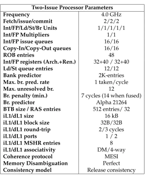
Table 3.1: Two-Issue processor parameters.
Two-Issue Processor Parameters
Frequency 4.0 GHz
Fetch/issue/commit 2/2/2
Int/FP/Ld/St/Br Units 1/1/1/1/1
Int/FP Multipliers 1/1
Int/FP issue queues 16/16
Copy-In/Copy-Out queues 16/16
ROB entries 48
Int/FP registers (Arch.+Ren.) 32+40 / 32+40
Ld/St queue entries 12/12
Bank predictor 2K-entries
Max. br. pred. rate 1 taken/cycle
Max. unresolved br. 12
Br. penalty (min.) 7 cycles (14 when fused)
Br. predictor Alpha 21264
BTB size / RAS entries 512 entries/ 32
iL1/dL1 size 16 kB
iL1/dL1 block size 32B/32B
iL1/dL1 round-trip 2/3 cycles
iL1/dL1 ports 1 / 2
iL1/dL1 MSHR entries 8
iL1/dL1 associativity DM/4-way
Coherence protocol MESI
Memory Disambiguation Perfect
Consistency model Release consistency Table 3.2: Parameters of the shared-memory subsystem.
Shared-memory Subsystem
System bus transfer rate 32GB/s Shared L2 4MB, 64B block size Shared L2 associativity 8-way
Shared L2 banks 16
L2 MSHR entries 16/bank
L2 round-trip 32 cycles (uncontended) Memory round-trip 320 cycles (uncontended)
Applications
We conduct the simulations on sequential workloads that comprise nine integer and eight floating point applications from the SPEC2000 suite [22]. We use the
MinneSpec reduced input sets [30]. In all cases, we skip the initialization parts and then simulate the applications to completion.1
3.2
Hardware Overhead
We compare the areas of all configurations.
Prior work [32, 31, 44, 45] shows that the area overheads of key microarchi-tectural resources scale superlinearly with respect to issue width in monolithic cores. Burns et al. [9] estimate the area requirements of out-of-order processors by inspecting layout from the MIPS R10000 and from custom layout blocks, finding that four- and six-issue cores require roughly 1.9 and 3.5 times the area of a two-issue core, respectively, even when assuming clustered register files, issue queues, and rename maps, which greatly reduce the area penalty of im-plementing large SRAM arrays.2 Recall also that our six-issue baseline’s first level caches and branch predictor are four times as large as those of a two issue core. Consequently, we model the area requirements of our four- and six-issue baselines to be two and four times higher than a two-issue out-of-order core, respectively.3
We estimate the area overhead of core fusion additions conservatively, as-suming that no logic is laid out under the metal layer for cross-core wiring. Specifically, we use the wiring area estimation methodology described in [33],
1Our simulation infrastructure currently does not support the other SPEC benchmarks. 2Note that, when all resources are scaled linearly, monolithic register files grow as O(w3),
wherewis the issue width. This is due to the increase in the number of bit lines and word lines per SRAM cell, times the increase in physical register count.
3We also experimented with an eight-issue clustered core (optimistically assumed to be
area-equivalent to the six-issue core), but found its performance to be inferior. Consequently, we chose the six-issue monolithic core as our baseline.
assuming a 65nm technology and Metal-4 wiring with a 280nm wire pitch [17]. Accordingly, we find the area for fetch wiring (74 bits/link) to be 0.30mm2, the area for rename wiring (244 bits/link) to be 1.56mm2, and the area for the operand crossbar (76 bits / link) to be 1.46mm2. The area of the commit wiring is negligible, as it is two bits wide. This yields a total area overhead of 3.32mm2for fusing a group of four cores, or 6.64mm2for our eight-core CMP. Using CACTI 3.2, we also estimate the total area overhead of the SMU, the extra i-cache tags, copy-in/copy-out queues, and bank predictors (four bank predictors, one per core) to be 0.68, 0.25, 0.26, 0.23mm2per fusion group, respectively, for a total of 2.84mm2 for the entire chip. Adding these to the wiring estimates, we find the total area overhead of core fusion to be 9.48mm2. Even for a non-reticle-limited, 200mm2die that devotes half of the area to the implementation of the cores, this overhead represents roughly three quarters of the area of one two-issue out-of-order core. Hence, we conservatively assume the area overhead to be equal to one core.
We estimate the latency of our cross-core wiring additions conservatively, as-suming that cores are laid out in a worst-case organization that maximizes cross-core communication delays. We assume that each group of four cross-cores in our eight-core CMP must communicate over a distance equal to one half of the chip edge length. Assuming a 65nm technology, a 4GHz clock, and 50ps/mm Metal-4 wire delay [17], we find that it is possible to propagate signals over a distance of 5mm in one cycle. Even for a reticle-limited, 400mm2 die with a worst-case floorplan, this represents a two-cycle cross-core communication latency. While these delays are likely to be lower for a carefully organized floorplan [33] or for smaller dice, we conservatively model fetch, operand, and commit communi-cation latencies to be equal to two cycles, and due to its wider links, we set the
bzip2 crafty gcc mcf parser perlbmk twolf vortex vpr g−mean 1 1.1 1.2 1.3 1.4 1.5 1.6 1.7 1.8 1.9 2
Speedup over Two
− issue 2.224 Two−issue Four−issue CoreFusion Six−issue
Figure 3.1: Speedup over base core for SPECINT benchmarks.
applu apsi art equake mesa mgrid swim wupwise g−mean
1 1.1 1.2 1.3 1.4 1.5 1.6 1.7 1.8 1.9 2
Speedup over Two
− issue Two−issue Four−issue CoreFusion Six−issue
Figure 3.2: Speedup over base core for SPECFP benchmarks.
latency of the rename communication to three cycles (which makes the rename pipeline add up to eight cycles).
3.3
Core-Fusion Performance
Figures 3.1 and 3.2 show speedups with respect to two-issue out-of-order core on SPEC 2000 applications. As expected, the results indicate that wide-issue cores have significant performance advantages on sequential codes.
Configura-tions with a six-issue monolithic core obtain average speedups of 73% and 47% on floating-point and integer benchmarks. (Speedups on floating-point bench-marks are typically higher due to higher levels of ILP present in these applica-tions.) Configurations that employ a four-issue core observe average speedups of 35% and 27% on floating-point and integer-benchmarks, respectively. Core fusion improves performance over the fine-grain two-issue out-of-order core by up to 81% on floating-point applications, with an average of 50%. On integer applications, up to 79% speedup improvements are obtained, with an average speedup of 30%.
In summary, the monolithic six-issue core performs best, followed by Core-Fusion’s fused core. While core fusion enjoys a high core count to extract TLP, it can aggressively exploit ILP on single-threaded applications by adopting a fused configuration.
3.4
Performance Analysis
In this section, we analyze and quantify the performance overhead of cross-core communication delays. We also investigate the efficacy of our distributed ROB and LSQ implementations.
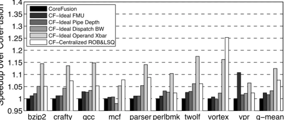
Distributed Fetch. Our fused front-end communicates taken branches across the FMU. Consequently, while a monolithic core could redirect fetch in the cy-cle following a predicted-taken branch, core fusion takes two additional cycy-cles. Figures 3.5 and 3.5 show the speedups obtained when the fused front-end is idealized by setting the FMU communication latency to zero. The performance impact of the FMU delay is less than 3% on all benchmarks except vpr,
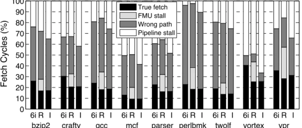
indi-6i R I 6i R I 6i R I 6i R I 6i R I 6i R I 6i R I 6i R I 6i R I 0 10 20 30 40 50 60 70 80 90 100 Fetch Cycles (%)
bzip2 crafty gcc mcf parser perlbmk twolf vortex vpr
True fetch FMU stall Wrong path Pipeline stall
Figure 3.3: Distribution of fetch cycles on SPECINT benchmarks. 6i, R, and I denote our six-issue monolithic baseline, a realistic fused front-end with a two-cycle FMU delay, and an idealized fused front-end with no FMU delay, respectively.
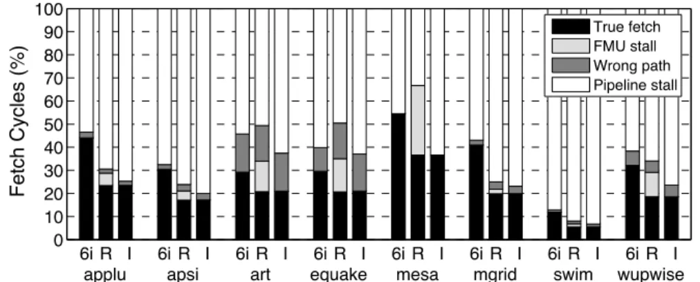
cating that there is significant slack between the fused front- and back-ends. Figures 3.3 and 3.4 illustrate this point by showing a breakdown of front-end activity for realistic (R) and idealized (I) FMU delays, as well as our six-issue monolithic baseline (6i). On memory-intensive floating-point applications, the fused front-end spends 35-95% of its time waiting for the back-end to catch up, and less than 5% of its time communicating through the FMU. On integer codes, 10-60% of the front-end time is spent communicating through the FMU, but re-moving this delay does not necessarily help performance: once the FMU delay is removed, the idealized front-end simply spends a commensurately higher portion of its total time waiting for the fused back-end. Overall, performance is relatively insensitive to the FMU delay.
SMU and the Rename Pipeline. Figures 3.5 and 3.6 show the speedups ob-tained when pipeline depth and the SMU are idealized (by reducing the eight-stage rename pipe to a single eight-stage, and allowing the SMU to dispatch an ar-bitrary number of instructions to each core, respectively). Depending on the
6i R I 6i R I 6i R I 6i R I 6i R I 6i R I 6i R I 6i R I 0 10 20 30 40 50 60 70 80 90 100 Fetch Cycles (%)
applu apsi art equake mesa mgrid swim wupwise
True fetch FMU stall Wrong path Pipeline stall
Figure 3.4: Distribution of fetch cycles on SPECFP benchmarks. 6i, R, and I denote our six-issue monolithic baseline, a realistic fused end with a two-cycle FMU delay, and an idealized fused front-end with no FMU delay, respectively.
application, the longer rename pipeline results in performance losses under 5%, with an average of less than 1%. While fusion increases the branch mispredic-tion penalty from seven to fourteen cycles, both the branch predictor and the BTB are four times as large in fused mode, decreasing misprediction rates and lowering sensitivity to pipe depth. The performance impact of restricted SMU bandwidth is more pronounced, and ranges from 0-7%, with an average of 3%. However, considering the wiring overheads involved, and the impact on the two-issue base cores, these performance improvements do not warrant an im-plementation with higher dispatch bandwidth.
Operand Crossbar. Figures 3.5 and 3.6 show the speedups achieved by an ide-alized operand crossbar with zero-cycle latency. Unlike communication delays incurred in the front-end of the machine, the latency of the operand crossbar affects performance noticably, resulting in up to 18% performance losses, with averages of 13% and 9% on integer and floating point applications, respectively. Sensitivity is higher on integer codes compared to floating-point codes: the
lat-bzip2 crafty gcc mcf parser perlbmk twolf vortex vpr g−mean 0.95 1 1.05 1.1 1.15 1.2 1.25 1.3 1.35 1.4
Speedup over CoreFusion
CoreFusion CF−Ideal FMU CF−Ideal Pipe Depth CF−Ideal Dispatch BW CF−Ideal Operand Xbar CF−Centralized ROB&LSQ
Figure 3.5: Speedups on SPECINT benchmarks when the FMU latency, rename pipeline depth, SMU dispatch bandwidth, operand crossbar delay, or the distributed ROB/LSQ are idealized.
applu apsi art equake mesa mgrid swim wupwiseg−mean 0.95 1 1.05 1.1 1.15 1.2 1.25 1.3 1.35 1.4
Speedup over CoreFusion
1.455
CoreFusion CF−Ideal FMU CF−Ideal Pipe Depth CF−Ideal Dispatch BW CF−Ideal Operand Xbar CF−Centralized ROB&LSQ
Figure 3.6: Speedups on SPECFP benchmarks when the FMU latency, rename pipeline depth, SMU dispatch bandwidth, operand crossbar delay, or the distributed ROB/LSQ are idealized.
ter are typically characterized by high levels of ILP, which helps hide the latency of operand communication by executing instructions from different dependence chains.
Distributed ROB and LSQ.Inevitably, core fusion’s distributed ROB and LSQ organizations suffer from inefficiencies that would be absent from a monolithic implementation (e.g., NOP insertion for aligned ROB allocation, and dummy
entry allocation in the LSQ). Figures 3.5 and 3.6 show that eliminating these inefficiencies improves performance by 7 and 23% over core fusion on integer and floating point codes, respectively. Along with the latency of the operand communication, this reduction in effective LSQ and ROB sizes has the highest impact on core fusion’s performance.
CHAPTER 4
CORE FUSION BASED ON IN-ORDER CORES
In the landscape of multicore chips, in-order cores are quickly gaining relevance–they are extremely power-efficient and simple, and they help max-imize core count, which is ideal for exploiting throughput oriented or highly parallel codes. In-order cores already have a significant presence in the server domain, where there is ample thread-level parallelism.
In this work, we propose mechanisms to facilitate dynamic aggregation of small, fundamentally-independent in-order cores to execute sequential code fast. Our hardwabased approach does not change the ISA, and does not re-quire compiler support. Unlike the case of out-of-order core fusion, where the base cores provide the design with valuable opportunities for latency hiding, minimally-provisioned in-order base cores leave little margin for inefficiencies.
In our design, loosely coupled cores process instructions at their own pace, and maintain the program state in a distributed manner. The modular and dis-tributed mechanisms require minimal central processing and functional repli-cation. In the course of formulating our solution, we devise: (1) A distributed checkpoint-based mechanism for bookkeeping of the program state; (2) a dis-tributed renaming mechanism; (3) a lightweight approach for disdis-tributed mem-ory disambiguation, and (4) a lightweight lookahead execution within each base core to partially hide cross-core communication and other latencies latencies. Our evaluation shows that a four-way fused configuration delivers a 45% per-formance gain over a single core, at the cost of 15% hardware overhead per core.
review-ing the base in-order core in the next section. We quantify the area overhead of core fusion and present its performance evaluation in Chapter 5.
4.1
Base In-order Core
We assume a chip multiprocessor targeted for 32nm technology node that com-prises single-issue, in-order, 8-stage-pipeline cores with 16KB private i- and d-caches1. Cores are grouped in four, and cores within each group share a unified L2 cache.
Figure 4.1 shows the base core’s pipeline structure. Most instructions fin-ish execution in one cycle, while integer multiply/divide, floating-point, and load instructions finish execution in three cycles2. The single write-back stage (WB) for all instructions guarantees in-order completion and update of the ar-chitectural state (except for load misses). It also simplifies arar-chitectural register file (ARF), by requiring a single write port (load misses may require another depending on implementation). All exceptions are caught at WB stage.
Direct jumps are processed at decode, while conditional branches and in-direct jumps are resolved at EXE1. Each core has a branch predictor, a branch target buffer (BTB), and a return address stack (RAS). On a misprediction, all newer instructions are flushed, and fetch resumes from the correct target ad-dress next cycle.
1Using Cacti5.3 [56], we estimate two-cycle access latency for the i- and d-caches, hence the
two stages for fetch and d-cache access.
2A double-precision floating-point unit in a SPE element of the IBM CELL processor consists
of a 9-cycle pipeline and has a cycle time of 11FO4 [40]. Assuming a latching delay of 2FO4, the latency of computation is 81 FO4. Accordingly, in our three-cycle pipeline, we must fit 27 FO4. Using ITRS [26] projections, we estimate that at 32 nm technology and at 4 GHz clock frequency, this amount of computation can easily fit in one cycle.
D - cache
Score-board
ISSUE EXE1 EXE2/MEM1 EXE3/
MEM2 WB ARF WrBuff DE BU FE2 FE1 I - cache BTAC
Figure 4.1: Pipeline of the base in-order core.
We assume a unified ARF with a split-cycle write/read implementation [21] (the write-back stage writes during the first half of a cycle, and the issue stage reads operands during the second half). This avoids structural hazards, and it allows consumer instructions to read operands just updated by producer in-structions in the first half cycle. The pipeline has all the needed bypass paths to EXE1 from later stages, in order to achieve back-to-back dependent instruction execution.
Effective addresses are calculated in EXE1. Stores are inserted into a FIFO write buffer (no store merging) in MEM1, and are issued to the cache from the buffer when they reach the WB stage and it is known that it is safe to perform the memory update. For loads, cache tag and data array accesses, as well as the check against the write buffer, are performed in parallel in MEM1. Data for-warding from the write buffer, if any, happens in MEM2; also in MEM2 the data array access is completed. Cache misses skip the write-back phase. They gen-erally do not block subsequent L1 accesses; the cache has miss-status handling registers (MSHR).
The core supports weak memory consistency, by ensuring that when a fence operation is at the head of the write buffer, it can complete only when all previ-ous stores have become globally visible. Also, loads cannot issue when there is at least one issued but incomplete prior fence in the pipeline.
The issue stage has a simple scoreboard to track data hazards due to multi-cycle operations. A Ready bit per register is reset when a multi-multi-cycle instruction issues, and set in a timely manner for bypassing. On a load miss, the Ready bit is set back assuming a hit. The RAW and WAW hazards on destination registers for load misses are handled via an Unknown-WB-Time bit per register. When a load issues, this bit is set, conservatively assuming a miss. It is reset either on a hit (on time to enable bypassing), or when a miss is eventually resolved and the result is written back to the ARF. A set Unknown-WB-Time bit for any of the source (RAW) and destination (WAW) registers of an instruction prevents it from issuing.
On a pipeline flush, instructions in the front-end including the issue stage are flushed. If the flush is due to an exception, caught at WB stage, then in-structions in the execution stages are allowed to drain, properly setting back the scoreboard bits, but without writing to the ARF.
4.2
Architecture
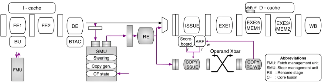
In this section, we describe the mechanisms to distribute execution of a single instruction stream over a group of four in-order cores, effectively constituting a four-issue processor. We strive for a modular approach that does not repli-cate functionality or employ complex structures typically seen in out-of-order processors. The following sections detail how we accomplish this. We explain our extensions extensively in detail, however the overall complexity and associ-ated area overhead remain relatively low (Section 5.2) Figure 4.2 highlights the components we introduce on top of a base core.
RE COPY ISSUE COPY RE/WB Steering Copy gen. CF state
SMU Operand Xbar
w r r
FMU
Abbreviations FMU: Fetch management unit SMU: Steer management unit RE : Rename stage CF : Core fusion DE BU FE2 FE1 I - cache BTAC D - cache Score-board
ISSUE EXE1 EXE2/MEM1 EXE3/
MEM2 WB
ARF
WrBuff
Figure 4.2: Core-fusion support on top of an in-order pipeline.
4.2.1
Distributed Program State
A base core modifies the program state in the architectural register file (ARF) in order at WB stage. A distributed execution, on the other hand, disperses the program state across the ARFs of all four cores. Retrieving a precise program state upon mispredictions or exceptions may not be possible, unless the design includes, for example, a global re-order buffer (ROB), as well as a global ARF or commit-time rename table. Adding such hardware support is not only costly, we believe it is unnecessary.
Checkpoint-based execution, where a processor periodically takes snap-shots of the program state, has been proposed as an alternative to ROB-based execution. It enables large instruction windows with relatively limited re-sources, and has been successfully used to enable speculative execution mecha-nisms [2, 41, 37, 54, 29].
We leverage checkpointing as a means to enable cost-effective bookkeeping of the program state across cores. It avoids fine-grain global commit of instruc-tions. On any event that requires program-state recovery (e.g. on misspecula-tion or excepmisspecula-tion), the last committed checkpoint is restored.
Our design retains a checkpointed program state in the ARF registers hold-ing the program-state values at the time of checkpointhold-ing. This pins those regis-ters during the lifetime of the checkpoint.3The distributed nature of our check-points necessitates a lightweight mechanism to coordinate global checkpoint allocation and recovery. We review the checkpointing support in Section 4.2.4, after we detail the architecture.
4.2.2
Distributed Fetch
We mostly borrow the approach for out-of-order core fusion to achieve collec-tive fetch across cores. Each core fetches one instruction, for up to four con-secutive instructions per cycle. Fetch is aligned such that the two lowest bits in the instruction address determine the fetching core. These two bits are not used in indexing predictor tables and caches, but are used in the tag, if any. For out-of-order core fusion, we add extra tags to reconfigure the i-cache into smaller cache blocks in fused mode, to utilize otherwise unused regions. These effectively build wider fetch, larger i-cache and branch predictor from smaller individual core components. In in-order core fusion, however, single instruc-tion granularity requires eight cache-tag arrays if we were to use the same i-cache reconfiguration approach. Our preliminary estimations revealed that this would significantly increase the area overhead relative to a base in-order core. We avoid this by leaving 3/4 of each i-cache block unused in fused mode, ef-fectively having the same aggregate amount of i-cache as in a base core. This simplification is reflected in our hardware-overhead estimation (Section 5.2) and
3Because the architectural state is distributed over four ARFs, which provide an aggregate
space four times the number of architectural registers, the cores may store checkpoints in place and still have free registers to work with.
evaluation (Section 5.4).
A Fetch Management Unit (FMU) coordinates fetch alignment and global branch-history update across cores, which results in one cycle fetch bubble on taken branches and two-cycle bubble on function returns through return-address stack in Core 0.
Due to checkpointed execution, branch predictions are assigned a confidence for checkpoint allocation on low-confidence branches. We use saturated coun-ters of four bits, and confidence threshold of fifteen. Confidence award is one, and penalty is seven. We record branch predictions and their confidence for each checkpoint interval, and reuse them after checkpoint recovery. Resolved branches correct their prediction record and set their confidence to high.
Each core independently decodes its instruction and sends it to a central-ized hardware structure that is responsible for instruction steering, named Steer-ing Management Unit (SMU). We assume one cycle link delay to the SMU (Sec-tion 5.2). The SMU is the only structure that observes the complete program flow. Therefore, it plays a critical role in satisfying the program order, specif-ically the register and memory dependences. It coordinates global checkpoint allocation and recovery, and steers instructions to cores. In the following sec-tions, we describe these mechanisms.
4.2.3
Satisfying Register Dependences
We introduce register renaming to allow preserving the checkpointed values in the ARF registers, efficiently utilize registers, and correctly track dependences.
We propose a distributed renaming technique to reduce coupling between SMU and cores, and simplify the SMU and rename logic. Each core indepen-dently and locally maps logical source and destination registers to its ARF reg-isters; the SMU does not manage register allocation and release, nor does it store any logical-to-physical mappings. We do not increase the size of each ARF–the distribution of the architectural state over the four cores automatically creates space in each ARF for renaming.
Distributed register renaming
Each core is augmented with a rename stage that comes prior to the issue stage (Figure 4.2). It renames instructions coming one at a time from the SMU, and inserts them into the regular issue queue for execution.
A Local Rename Table (LRT) in the rename stage maps logical registers to the local ARF registers. Different from typical rename tables, some LRT entries might be invalid, and some valid mappings might be stale if a logical register is more recently mapped in another core. Only the SMU knows and keeps track of the core that has the most recent mapping for each logical register in a table.
Only local source operands locate their ARF register via the LRT. A remote source operand (appropriately tagged by the SMU) allocates a new local ARF register from the free-register list without updating the LRT. The remote value will be brought into the register by acopy instructioninjected by the SMU into the sourcing core. The ARF register identifier is recorded in a small table called Remote Operand Table (ROT).The ROT is a RAM array, indexed by a remote-operand idthat is assigned by the SMU at the time of steering. The id is also
at-tached to the corresponding copy instruction, so that the two instructions match on a common ROT entry. When the copy instruction arrives at the destination core, it checks the ROT entry to learn the ARF register to copy over.
It is possible that the copy instruction arrives before the regular instruction is renamed. In this case, which is detected through invalid ROT entry, the copy instruction allocates an ARF register and records it in the ROT. The regular in-struction finds the entry valid and uses that register to rename its remote source operand. When the ROT entry is consumed by the second instruction, the ROT entry is invalidated.
The size of the ROT is large enough to accommodate the maximum number of remote operands in the issue queue.4 SMU generates remote-operand ids per core using a wrap-around counter. Free-ROT-entry assignment is guaranteed by (1) securing a free issue-queue entry before dispatching an instruction and its copy instruction(s), and (2) releasing issue queue entries in order, already being the case.
Finally, renaming a destination register simply allocates a free ARF register and updates the LRT.
Because of renaming, an ARF register’s Ready bit in the scoreboard is reset at the time the register is allocated from the free-register list. For locally produced registers, it is set in the main pipeline as in the base core. For remote-operand registers, it is set by the copy instruction upon value delivery.
Because the SMU does not know a priori whether there are free registers in the cores, it is possible that an instruction may be unable to secure an ARF
regis-4In an alternative implementation, the SMU can constrain the number of remote operands
ter during renaming. In this case, the instruction is marked as having raised an exception. At WB stage, the failure will be communicated to the SMU as a Re-name Failure, and it will cause the architecture to roll back to the last committed checkpoint. When a rename failure occurs on copy-induced register allocation, the failure is propagated to the consumer instruction through a flag in the ROT entry. It is easy to guarantee forward progress on rename failures, by making cores send aFree-Register Thresholdsignal to the SMU when the number of free ARF registers drops below a predetermined threshold. Upon receiving such a signal by any core, the SMU initiates checkpoint allocation, which guarantees absence of rename failures up to that point (baring mispredictions or excep-tions). We dynamically adjust this threshold between an aggressive and a con-servative one based on the occurrence of rename failures, to minimize rollback events. The SMU also takes measure to prevent mapping too many registers to a core (Section 4.2.8).
Remote-operand transfer flow
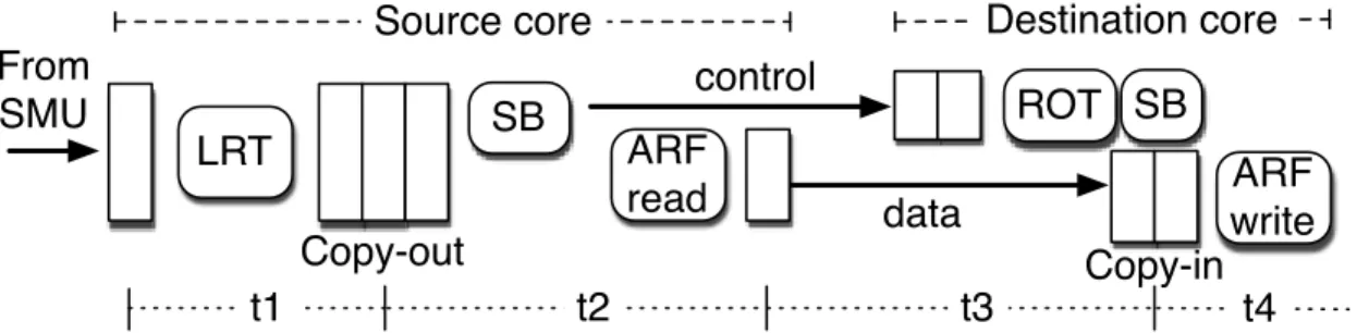
This section details the copy-instruction flow (Figure 4.3). At a high level, the SMU dispatches a copy instruction to the source core where the remote operand value currently resides. Upon reading the value, the copy instruction delivers it to the core of the instruction with the remote operand, over a cross-core full crossbar.
Copy instructions share the same path with the regular instructions from the SMU up to and including the rename stage in the source core. This ensures properly ordered renaming. Because their source operand is always local, they use the LRT to locate the ARF register. Afterwards, they are placed in a FIFO
From SMU Copy-out LRT SB ARF read ROT control data Copy-in
Source core Destination core
ARF write
t1 t2 t3 t4
SB
Figure 4.3: Copy-instruction flow through the source and destination cores. SB is short for scoreboard.
RAM copy-out queue (separate from the issue queue) for issue. The copy in-struction at the head of the copy-out queue checks the scoreboard for operand readiness, in the same way regular instructions do. When it issues, it reads the ARF5, and goes to its destination core where it is placed in acopy-inqueue. Pro-cessing copy instructions at the source core, thus, requires an additional read port to both the scoreboard and the ARF.
We assume that the remote-operand id precedes the data transfer, to make room for (1) multiplexing among copy instructions from other cores, (2) locat-ing the ARF register through ROT (Section 4.2.3), and (3) settlocat-ing the Ready bit of that register so that a consumer instruction can issue earliest next cycle, all in the destination core.6 When issued from the copy-in queue, the copy instruc-tion updates the ARF register and terminates. The aforemeninstruc-tioned operainstruc-tions require one extra write port to the Ready bit array. Copy-in queue accesses use the extra write port originally reserved for load misses.
Renaming and proper register release (Section 4.2.5), together ensure that no WAW and WAR hazards occur between instructions in the copy queues and
5We assume proper bypassing from the main pipeline.
6In rare cases, the Unknown-WB-Time flag of the register is set. This cancels the write-back
of the copy instruction. Eventually, when the load miss resets the flag, the copy instruction resumes. This requires one read port to the Unknown-WB-Time array.
regular issue queue. (Recall that, checking the scoreboard for operand readiness handles the RAW hazards.)
4.2.4
Checkpoint Allocation, Commit, and Recovery
Our preliminary studies showed that a lightweight checkpoint management that does not block instruction flow is critical to performance. This led us to implement a novel distributed and nonblocking checkpointing approach.
Checkpoint allocation and commit
To allocate a checkpoint, the SMU generates a special Checkpoint instruction, which is dispatched to all cores. These are interleaved with ordinary instruc-tions cutting them in waves. ACheckpointpasses through the main pipeline in a core. It checkpoints the LRT at the rename stage. At this time, it is guaran-teed that all instructions prior to the checkpoint have updated the LRT. Only valid and non-stale mappings need to be checkpointed, which are conveyed by the SMU along with the Checkpointinstruction. The checkpointed registers are pinned and not allowed to be released/overwritten until the checkpoint is released. On successful completion at WB stage, it notifies the SMU in order, so that the SMU properly orders multiple in-flight checkpoint allocations and determine the final action for each. The SMU deems a checkpoint committed when it receives the acknowledgements from all cores. Then, it sends aCommit signal to all cores. Each core commits the oldest non-committed checkpoint, and releases the last committed one. Because checkpoints are handled at WB, they are committed in order.
Checkpoint recovery
A mispredicted or except