Prediction of Minimum Chip Thickness in Tool Based Micro
End Milling
Mohammad Yeakub Ali*, Ahsan Ali Khan, Asfana Banu Mohamad Asharaf,
Adibah Abdul Wahab
Department of Manufacturing and Materials Engineering, Faculty of Engineering, International Islamic University Malaysia, P.O. Box 10, 50728 Kuala Lumpur, Malaysia.
Received 30 June 2011; accepted 27 Feb 2012,available online 16 May 2012
1.
Introduction
Micro end milling is one of the micro meso mechanical manufacturing (M4) technique where a miniaturized tool is used to fabricate complicated three dimensional (3D) micro features. The low stiffness, size effect and ploughing are found to be the main issues in micro end milling [1, 2]. Tungsten carbide in a cobalt matrix (WC-Co) is used as tool material as a tool material with a diameter ranging from 0.2 to 1 mm. The rigidity of the tool will decrease when the tool diameter decrease [3]. The available micro tools have edge radius from 1-5
μm. The challenges faced in micro end milling are as follows:
i. Tool failure: Micro end milling tools can often fail by fracture at the tool root, as opposed to edge wear. Because of the small tool diameter, the cutting forces must not exceed the bending stress limit of the tool.
ii. Chip load: In order to keep the cutting forces sufficiently small, the chip thickness must be less than 1 μm.
iii. Cutting edge radius: Commercially available tools have cutting edge radii on the order of 2-3
μm, substantially higher than the desired chip thickness. So the effective rake angle is highly negative and leading to higher cutting force compared to conventional milling.
iv. Spindle run out: Commercially available micro milling spindles have radial run out of 1-2 μm, larger than the desired chip thickness. It will lead to overloading of the tool and premature failure.
v. Cutting speed: As the tool diameter decreases, the spindle speed must increase to achieve the optimum peripheral cutting speed. For very small tools, around 500000 rpm is required [4]. vi. Roughness: The surface roughness in micro end
milling is higher compared to lithography based techniques [5].
vii. Sharp corners: The inability of micro end milling to produce sharp corners because of having a curvature equal to the radius of the milling tool [6].
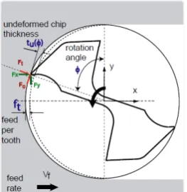
In micromachining, due to the limited strength of the micro tool, the uncut chip thickness is constrained to be comparable or even less than the tool edge radius. As a result, a chip will not be generated if the uncut chip thickness is less than critical values which is called as the minimum chip thickness. Cutting forces, tool wear, surface integrity process stability play vital roles in affecting the production of the minimum chip thickness [3]. The tool edge radius and small feed per tooth make the phenomenon of minimum chip thickness critical in the micro end milling. A minimum chip thickness is formed when the tool is engage with workpiece which will effect in chip formation. In full immersion micro end milling uncut chip thickness of tu (Ø) varies from zero to feed per tooth shown in Fig.1. The minimum chip thickness is defined as the minimum undeformed thickness of the chip removed from a workpiece under perfect metal-cutting condition [3]. The chip is not formed and elastic deformations are induced to the workpiece until tool reaches to a certain rotation angle where a minimum uncut chip thickness develops. Early formation of minimum chip thickness is caused by
Abstract: This paper presents the analysis and modelling of minimum chip thickness by tool based micro end milling with control parameter of cutting speed, feed rate, and depth of cut. The formed chip thickness was measured using scanning electron microscope The data were analyzed and an empirical model is developed. The optimum value for the minimum chip thickness was 375 nm with cutting speed of 2275 rpm, feed rate of 2.6 mm/min, and depth of cut 0.6 μm using Ø 0.8 mm tool. The analysis revealed that the depth of cut is the most influential parameter on the minimum chip thickness. The investigation was performed on poly methyl methacrylate (PMMA) using integrated multi-process micro machine tools DT 110. The minimum chip thickness is found to be important to avoid tool breakage, deterioration of surface finish and to increase the tool life.
smaller edge radius but larger edge radius will effect in ploughing of the workpiece. It was observed experimentally that the minimum chip thickness depends on the ratio of uncut chip thickness to the cutting edge radius, for ductile material [7, 8]. The minimum chip thickness to edge radius ratio is used to describe the formation of minimum chip thickness. This ratio was found to be 0.35-0.4 for micro milling AL6082-T6 aluminum and 0.2-0.3 for AISI 1018 steel at a wide range of cutting speed and edge radius [9]. Thus, the objective of this paper is to study is to develop a model for minimum chip thickness using various feed rate, depth of cut, and cutting speed.
Fig. 1 Chip thickness and planar forces during micro end milling process [3].
2.
Experiment
Taguchi’s L18 orthogonal array was used to conduct the experiments. Eighteen experiments were conducted in order to analyze the minimum chip thickness using Ø 0.8 mm cutting tool with 50 μm cutting edge radius. The experimental parameters are shown in Table 1.
PMMA is used as the substrate for this project since it is widely used in producing micro channels [10]. Besides that, this material can be cut at low cutting speeds and low feed rate. The specimen dimension was 50 mm x 50 mm x 10 mm. Two-flute tungsten carbide end mill tool of 0.8 mm diameter was used in this experiment.
The micro end milling is conducted with a multi-purpose miniature commercial machine tool known as Mikrotools Integrated Multi-process Machine Tool DT 110 (Mikrotools Inc., Singapore). This machine also enables changeable high speed, middle speed and low speed spindles. The micro end milling process started with setting up the workpiece in the cutting holder. After that, the parameters were inserted in NC program before running the machining process. The chips were collected
on carbon tape. The image of the chip thickness was taken by SEM (JEOL, Japan). One of the machined micro channels and the formed chips are shown in Fig. 2.
3.
Measurement
The thickness of a chip was measured at different location along its entire chip length by SEM observation using the scalar function in the image that scanned by SEM and listed as in Table 2. The magnification of the scanned image is x2000. Three different chips were taken from each experiment and the average of the dimension of chip thickness was calculated.
The measured chip thickness values, as listed in Table 2, have been analyzed performed in micro end milling machine using different diameter of cutting tools has been analyzed and are tabulated. Analysis of variance (ANOVA) approach was used to check the sufficiency of the model. The analysis showed the main and interaction effects of the process variables on the responses. The chips are formed in the type of continuous and discontinuous.
a b
Fig. 2 Micro end milling on PMMA workpiece (a) machined microchannel, (b) microchips
4.
Analysis and Discussions
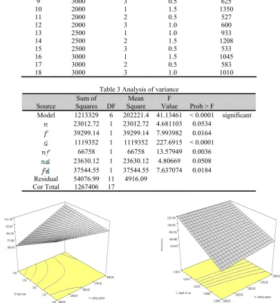
ANOVA was used to check the influence and interaction of the parameters on chip thickness. The model used for analysis was response surface 2FI model. Then, the Eq. 1 for the estimation of chip thickness was developed from this model. The analysis shows the F value of 41.13 that implies the model is significant. The value of Prob > F less than 5% indicates the model terms
n, f, d, nf, nd, and fd are significant. fd nd nf d n tc 7 . 146392 3 . 232 2 . 0 2 . 930601 6 . 694 06 . 0 8 . 835 + − + + − −
= (1)
where, tc = chip thickness (nm), n = cutting speed (rpm), f
= feed rate (mm/min), and d = depth of cut (μm).
Table 1 Experimental parameters Level
Control Parameters Factor I II III
Cutting speed (rpm) 2000 2500 3000
Feed rate (mm/min) 1 2 3
Depth of cut (μm) 0.5 1.0 1.5
Workpiece material PMMA( poly methyl methacrylate )
Cutting tool Two-fluted tungsten carbide end mill tool bit
Cutting tool diameter (mm) Ø 0.8 mm x R0.05 mm x 6 mm,
Machining length 10 mm
Table 2 Experimental parameters and measured chip thickness
Parameters Response
Expt. Cutting speed
(rpm) (mm/min) Feed rate Depth of cut (µm) Chip thickness (nm)
1 2000 1 0.5 650
2 2000 2 1.0 815
3 2000 3 1.5 1205
4 2500 1 0.5 775
5 2500 2 1.0 915
6 2500 3 1.5 1215
7 3000 1 1.0 983
8 3000 2 1.5 1233
9 3000 3 0.5 625
10 2000 1 1.5 1350
11 2000 2 0.5 527
12 2000 3 1.0 600
13 2500 1 1.0 933
14 2500 2 1.5 1208
15 2500 3 0.5 533
16 3000 1 1.5 1045
17 3000 2 0.5 583
18 3000 3 1.0 1010
Table 3 Analysis of variance
Sum of Mean F
Source Squares DF Square Value Prob > F
Model 1213329 6 202221.4 41.13461 < 0.0001 significant
23012.72 1 23012.72 4.681103 0.0534 39299.14 1 39299.14 7.993982 0.0164
1119352 1 1119352 227.6915 < 0.0001
66758 1 66758 13.57949 0.0036
23630.12 1 23630.12 4.80669 0.0508 37544.55 1 37544.55 7.637074 0.0184
Residual 54076.99 11 4916.09
Cor Total 1267406 17
(a) (b) Fig. 3 Three dimensional plot for determining chip thickness (a) cutting speed vs. feed rate, (b) cutting speed vs. depth
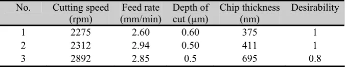
Table 4 Optimization result for minimum chip thickness using Ø 0.8 mm cutting tool
No. Cutting speed
(rpm) (mm/min) Feed rate Depth of cut (µm) Chip thickness (nm) Desirability
1 2275 2.60 0.60 375 1
2 2312 2.94 0.50 411 1
3 2892 2.85 0.5 695 0.8
Fig. 3 shows the 3D plot of the interaction between the parameters. Fig. 3 (a) shows when the cutting speed is low, the chip thickness is higher at lower feed rate. On the other hand, Fig. 3 (b) shows that the chip thickness increases when the cutting speed and depth of cut increases.
5.
Optimization
By using Design Expert, the optimization is based on a response and three parameters. There are two optimum solutions in order to get minimum chip thickness. The minimum value of chip thickness for Ø 0.8 mm cutting tool (Table 4) is 375 nm with 2275 rpm cutting speed, 2.6 mm/min feed rate and 0.6 μm depth of cut.
6.
Conclusion
This paper discussed the experimental study that had been done in order to find the minimum chip thickness in micro end milling on PMMA. The three parameters; cutting speed, feed rate, and depth of cut were used in the investigation. The Taguchi orthogonal array method was used for modelling. The optimization of minimum chip thickness in micro end milling was carried out. The optimum value for the minimum chip thickness was 375 nm with 2275 rpm cutting speed, 2.6 mm/min feed rate and 0.6 μm depth of cut using Ø 0.8 mm cutting tool. Therefore, it can be concluded that:
1. In order to get the minimum chip thickness, low cutting speed, low feed rate and depth of cut in the range of 0.5 µm to 0.6 µm would be appropriate. 2. The depth of cut is the crucial parameter followed
by feed rate and cutting speed in order to get the minimum chip thickness.
3. The investigation is done to predict the minimum chip thickness on PMMA. So the results are relevant only for polymer as it is a homogeneous and isotropic material.
4. The model (Eq. 1) presented here is based on experimental data. As the analytical modelling includes many interrelated parameters such as material properties, tool geometry, and cutting parameters, it is very complex and difficult to apply.
5. The develop model is simple and easy to apply although it has limitation.
Acknowledgement
This research was funded by The Ministry of Higher Education, Malaysia under Research Grant FRGS0207-44. The authors are thankful to Micromanufacturing Laboratory where the experimental studies were performed.
References
[1] Uriarte, L., Herrero, A., Zatarain, M., Santiso, G., Lopez de Lacalle, L.N., and Lamikiz, A., (2006), Error Budget and Stiffness Chain Assessment in a Micromilling Machine Equipped with Tools Less than 0.3 mm in Diameter. Precision Engineering 31, p. 1-12.
[2] Uriarte, L., Ivanov, A., Oosterling, H., Staemmler, L., Tang, P.T., and Allen, D., (2006), A Comparison between Microfabrication Technologies for Metal Tooling. Journal of Mechanical Engineering Science 220, p. 1665-1676.
[3] Dhanorker, A., Liu, X., and Özel, T., (2007),
Micromilling Process Planning and Modeling for Micro Mold Manufacturing. International Conference on Manufacturing Science and Engineering Atlanta, GA. (31070).
[4] Zieger, J.C., and Pathak, J.P., (2003), Design. Assembly and Testing of an Ultra-high Speed Micro-milling Spindle, MSc Thesis, University of Florida. [5] Guber, A.E., Heckele, M., Herrmann, D., Muslija,
A., Saile, V., Eichhorn, L., Gietzelt, T., and Hoffmann, W., (2004), Microfluidic Lab on a Chip Systems based on Polymers– Fabrication and Application. Chemical Engineering Journal 101(1-3), p. 447-453.
[6] Mecomber, J.S., Stalcup, A.M., Hurd, D., Halsall, H.B., Heineman, W.R., Seliskar, C.J., Wehmeyer, K.R., and Limbach, P.A., (2006), Analytical Performance of Polymer-based Microfluidic Devices Fabricated by Computer Numerical Controlled Machining. Analytical Chemistry 78, p. 936-941.
[7] Kim, C.J., Bono, M., and Ni, J., (2002),
Experimental Analysis of Chip Formation in Micro-milling. Transactions of NAMRI/ SME. 30, p. 247-254.
[8] Kim, C.J., Mayor, J.R., and Ni, J., (2004), A Static Model of Chip Formation in Microscale Milling. Journal of Manufacturing Science and Engineering 126, p. 710-718.
Manufacturing Science and Engineering 128, p. 474-481.
[10]Ali, M.Y., (2009), Fabrication of Microfluidic Channel using Micro End Milling and Micro