Implementation of 128, 192 & 256 bits
Advanced Encryption Standard on
Reconfigurable Logic
Monika Gupta
1, Swapnil Mahto
2, Ambresh Patel
3M.tech Scholar1, Assistant Professor2, Assistant Professor,3 Sri Satya Sai College of Engineering
Bhopal M.P. India
Abstract - Advanced encryption standard is adopted by NIST to replace data encryption standard, which was affected by several attacks. In this paper implementation of all three modes namely 128, 192 and 256 of advanced encryption standard is discussed for reconfigurable logic. All these modes are implemented using four design architectures namely: 2 stage sequential, 3 stage sequential , combinational and pipelined.
Keywords - Advanced encryption standard,
Sequential, combinational, pipelined, encryption, cryptography
I. INTRODUCTION
The Advanced Encryption Standard denotes the Rijndael algorithm that can access 128 bits of data blocks using keys of 128, 192, 256 bit length. The Advanced Encryption Standard encipher exchanges data to an unintelligible form using the cipher key and the Advanced Encryption Standard decipher exchanges the cipher text back to plain text using similar cipher key. In Advanced Encryption Standard (AES) similar key is used for both decryption and encryption. Cryptography is an effective way of protecting sensitive information as it is stored on media or transmitted through network communication paths. Although the ultimate goal of cryptography, and the mechanism that make it up, is to hide information from unauthorized individuals. The approach of the project is towards advanced encryption standard algorithm that widely used algorithm in nowadays cryptographic technique. Advanced Encryption Standard decryption and encryption are concerned on four various transformations applied again and again in a specific input data consequences and the data flows of decryption and encryption are not similar. An expansion key module is used to distribute keys for several iterations of the AES algorithm. Depending on the input key length, the number of iterations of the Advanced Encryption Standard algorithm will vary.AES algorithm is an iterated symmetric block cipher which means that it works by repeating the same defined steps multiple times. In cryptography, AES is called as Rijndael Encryption algorithm that is capable of protecting sensitive information. [5]
II. AESFRAMEWORK
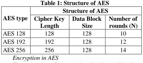
Table 1 shows the structure of Rijndael Algorithm adopted by AES. AES uses the data block of 128 bits and Cipher key of 128, 192 or 256. The number of rounds for AES 128, AES 192 and AES 256 are 10, 12 and 14 respectively. In each round a same set of operations are performed [2].
Table 1: Structure of AES
AES type
Structure of AES Cipher Key
Length
Data Block Size
Number of rounds (N)
AES 128 128 128 10
AES 192 192 128 12
AES 256 256 128 14
Encryption in AES
The process of encryption begins with the conversion of 128 bit data to a 4 x 4 state matrix of 16 bytes. Similarly the input cipher key is also converted to a 4 x 4 matrix of 16 bytes. For AES – 128, the cipher key matrix size of 16 byte is same the cipher key size 128 bits (16 bytes). For AES 192 and AES 256, the first 128 bits (16 bytes) are used in first round and the remaining bits are used in next round. The set of operations performed in each round are listed below.
1. Add_Round_key: in this operation the state matrix is xored with the cipher key matrix and a new state matrix is formed.
2. Sub_bytes: in this operation each byte of state matrix is replaced by a byte form a 256 byte table called SBOX.
3. Shift_rows: State matrix has 4 rows, in this operation the first row is not shifted, the second row is shifted left cyclically by 1 byte, the third row is shifted left cyclically by 2 bytes and the fourth row is left shifted cyclically by 3 bytes. Mix_column: A linear transformation is used in this process. The mix column is process is used in 4 columns.
III.IMPLEMENTATION
techniques have their own pros and cons which will be discussed in following sections.
3 Stage Sequential Implementation of AES
Figure 1 depicts the sequential 3 – stage implementation of AES. In this technique first the plain text is converted into state array and then it is XORED with input cipher key (cipher key length is 128, 196 and 256 for AES 128, AES 192 and AES 256 respectively.) in the add_round process. Then the rounding process (round 1 to round N-1) is implemented using a unit which has four sub units in it namely: Sub_Bytes, Shift_Rows, Mix_Column and Add_Round_Key. Then the last round is implemented using another unit which has only three sub units namely: Sub_Bytes, Shift_Rows and Add_Round_Key. This is a low area implementation as it uses the same hardware for round 1 to round N-1.
Figure 1: 3-Stage Sequential Implementation of AES
2 stage Sequential Implementation of AES
Figure 2 shows the implementation of 2 stage sequential machine for AES. In this first the plain text is converted to state matrix and then it is XORED with the input cipher key. Then from round 1 to round N-1 the state array goes from the four subunits namely: Sub_Bytes, Shift_Rows, Mix_Column and Add_Round_Key. In the last round (Nth round) the mix column process is not used and the state array goes through only three remaining subunits. This technique also uses hardware sharing as the four subunits are used N times to generate the final cipher text. In this technique the resource usage will further reduce as compared to 3 stage sequential implementation as it does not uses one more unit for the last round.
Figure 2: 2-Stage Sequential Implementation of AES
Combinational Implementation of AES
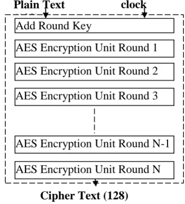
Combinational implementation is a high speed implementation technique, in this method all the rounds are implemented using separate rounding units, so a sum of N rounding units are required to implement the complete design.
Figure 3: Combinational Implementation of AES Figure 3 shows the hardware equivalent of combinational module of AES. This technique requires huge area (resources) as it used 10 rounding units compared to 2 rounding units in sequential 3 stage machine and single rounding unit in 2-stage sequential machine. Also the area requirement grows with number of rounds, the number of rounds for AES 128, AES 192 and AES 256 are 10, 12 and 14 respectively which means 10 rounding units are required to implement AES 128, 12 rounding unit are required to implement AES 192 and 14 rounding units are required to implement AES 256. The major advantage of combinational technique is low delay as N units are working in parallel compared to a single or two units.
Internal architecture of round 1 to round N-1 is same and it uses four subunits namely: Sub_Bytes, Shift_Rows, Mix_Column and Add_Round_Key.
Plain Text
(128)
Add Round Key
AES Encryption Unit Round 1
AES Encryption Unit Round 2
AES Encryption Unit Round 3
AES Encryption Unit Round N-1
AES Encryption Unit Round N
Cipher Text (128)
clock
Add_round unit
AES Encryption Unit Round (1 to N)
Controller Key Expansion
unit
AES Decryption unit Round (1 to N)
Add_round unit Plain Text Cipher Key Plain Text
Cipher Text Cipher Text
Add_round unit
AES Encryption Unit Round (1 to N-1)
AES Encryption unit Round N
Controller Key Expansion
unit
AES Decryption unit Round N
AES Decryption Unit Round (1 to N-1)
Add_round unit
Plain Text Cipher Key Plain Text
Figure 4 shows the internal architecture of round 1 to round N-1.
Figure 4: Round 1 to Round N – 1 of AES combinational
Internal architecture for round N is different from round 1 to round N-1 as it does uses mix_column subunit and uses only the remaining three subunits. Figure 5 shows the internal structure of round N of AES combinational.
Figure 5: Round N of AES combinational
Pipelined Implementation of AES
The combinational technique is used to decrease the delay and increase throughput. Further increase in throughput can be obtained by using pipelining technique. In this technique a 128 bit register is used after each rounding unit to store the data temporarily. Figure 6 shows the internal structure of pipelined architecture of AES.
Figure 6: AES Pipelined design
At clock 1 the input data packet 1 is add_rounded and then stored in a 128 bit register. Then in the next clock the stored data in register 1 is assigned to round 1 unit and stored in register 2 and simultaneously the next data packet 2 is add_rounded and stored in register 1 in the same clock duration. This process continues for all the rounds. After N clock pulses the final cipher text 1 is obtained and then in the next clock cipher text packet 2 is obtained corresponding to the input packet 2. Now the cipher text packets will continue to stream at every clock pulse. The maximum operating frequency is derived from the delay of one round rather than the delay of sum of the all the rounds as in combinational design. The major advantage of pipelined technique is high operating
speed and frequency. The internal architecture of rounds is same as that of combinational design shown in figure 4 and 5.
Figure 6: Pipelined AES
IV.RESULT
Figure 7 shows the simulation of AES – 2 stage design. 39 clocks used for 1st output. 2nd output available after 78 clock cycles. Single round delay is 7.98ns and overall total delay is 311.22ns.
Figure 7: Simulation – AES – 2 stage Figure 8 shows the simulation of AES – 3 stage design. 23 clock cycles used for 1st output & 2nd output available after 46 clock cycles. Single round delay is 9.765ns & overall total delay is 224.595ns
Figure 8: Simulation – AES – 3 stage Figure 9 shows the simulation of AES – Combinational. 1 clock used and 2nd output available at 2nd clock but Single round delay is 219.866ns & overall total delay is 219.866ns.
Figure 9: Simulation – Combinational Figure 10 shows the simulation of AES – Pipelined. 10 clock cycles used & output from 11th
Sub_bytes
Shift_rows
Mix_column
Add_Round_Key
Sub_bytes
Shift_rows
Add_Round_Key
Cipher Text (128) Plain Text -128 Clock
Add Round Key
AES Encryption Unit Round 1
AES Encryption Unit Round 2
AES Encryption Unit Round 3
AES Encryption Unit Round N-1
AES Encryption Unit Round N Register 1
Register 2
Register 3
Register 4
Register N-1
clock + stream of data available. Single round delay is 11.078ns and overall total delay is 110.78ns.
Figure 10: Simulation – Pipelined
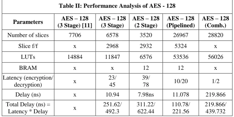
In this section various design are compared in terms of area and delay. Table II shows the performance analysis of AES 128 bit implementation.
Table I shows the performance analysis of AES – 128. As previous work available in literature we have been able to reduce area in terms of LUTs & Slices to a great extent in 2 stage implementation. The overall delay of 3 stage implementation and 2 stage implementation are very high as their latency is high. In order to reduce delay we have designed two more architectures called pipelined and combinational. In In terms of overall delay the pipelined architecture is best as cipher text output streams after the 10 clock cycles for encryption and 20 clock cycles for decryption.
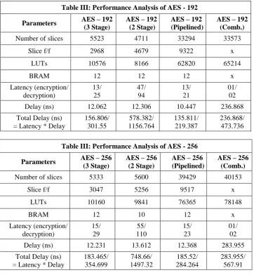
Table II shows the performance analysis of AES -192, it can be inferred from table II that, AES 2 stage is the best in terms of area usage as it uses the minimum area, but worst in terms of overall delay. The AES – 192 Pipelined architecture is best in terms of overall delay as it is least and also the output cipher text/plain text streams after 13/21 clock cycles i.e. after each clock new output is generated corresponding to the new input vector. The cost paid is area.
Table III shows the performance analysis of AES – 256, that AES – 2 Stage and AES - 3 stage are almost same in terms of area (resource usage), but AES 2 – Stage is worst in terms of latency and overall delay. So for AES – 256 it can be interpreted that AES – 2 stage is of not much use as it has highest overall delay and similar area usage comparable to the 3 stage implementation. AES – 256 combinational implementation is best in terms
of latency but the overall delay is dependent on combinational delay which is worst in combinational implementation. So similar to the AES – 128 and AES 192, the pipelined architecture is best in terms of overall delay. The output of encryption and decryption blocks streams after the latency clock cycles (15 and 23 for encryption and decryption respectively)
V. CONCLUSION
In this work we have implemented all the three modules of AES, namely AES – 128, AES 192 and AES – 256. All the three modules are implemented from the four different techniques namely: 3 stage, 2 Stage, Pipelined and combinational. It can be interpreted from the results that 2 stage design is best in low area requirement systems for AES 128 and AES 192, but the area (resource usage) is almost same to 3 stage design in AES – 256 module. The cost paid is overall delay. The pipelined architecture is best in terms of overall delay for the all the three AES modules. Another advantage of using pipelined architecture is that the output of encryption and decryption module streams after specified latency clock cycles i.e. new output is generated after each clock cycle corresponding to the new input. The maximum operating frequency is dependent on delay, and it is the reciprocal of delay (not overall delay), the pipelined architecture has moderate delay in the three modules of AES and hence it can be operated on a high frequency compared to the combinational design.
In this work the three modules of AES works independently and are separate designs, in future three modules can be combined so that a single machine will be able to support all the three modules and also hardware can also be shared to conserve area.
Table II: Performance Analysis of AES - 128
Parameters AES – 128
(3 Stage) [11]
AES – 128 (3 Stage)
AES – 128 (2 Stage)
AES – 128 (Pipelined)
AES – 128 (Comb.)
Number of slices 7706 6578 3520 26967 28820
Slice f/f x 2968 2932 5324 x
LUTs 14884 11847 6576 53536 56026
BRAM x x 12 12 x
Latency (encryption/
decryption) x
23/ 45
39/
78 10/20 1/2
Delay (ns) x 10.94 7.98ns 11.078 219.866
Total Delay (ns) =
Latency * Delay x
251.62/ 492.3
311.22/ 622.44
110.78/ 221.56
Table III: Performance Analysis of AES - 192
Parameters AES – 192
(3 Stage)
AES – 192 (2 Stage)
AES – 192 (Pipelined)
AES – 192 (Comb.)
Number of slices 5523 4711 33294 33573
Slice f/f 2968 4679 9322 x
LUTs 10576 8166 62820 65214
BRAM 12 12 12 x
Latency (encryption/ decryption)
13/ 25
47/ 94
13/ 21
01/ 02
Delay (ns) 12.062 12.306 10.447 236.868
Total Delay (ns) = Latency * Delay
156.806/ 301.55
578.382/ 1156.764
135.811/ 219.387
236.868/ 473.736
Table III: Performance Analysis of AES - 256
Parameters AES – 256
(3 Stage)
AES – 256 (2 Stage)
AES – 256 (Pipelined)
AES – 256 (Comb.)
Number of slices 5333 5600 39429 40153
Slice f/f 3047 5256 9517 x
LUTs 10160 9841 76365 78148
BRAM 12 10 12 x
Latency (encryption/ decryption)
15/ 29
55/ 110
15/ 23
01/ 02
Delay (ns) 12.231 13.612 12.368 283.955
Total Delay (ns) = Latency * Delay
183.465/ 354.699
748.66/ 1497.32
185.52/ 284.264
283.955/ 567.91
REFERENCES
[1] Hammad I, El-Sankary K, El-Masry E, “High-speed AES
encryptor with efficient merging techniques,” IEEE Embedded Systems Letters, 2010, pp.67-71.
[2] I ZHANG Y L, WANG X G, “Pipelined implementation of
AES encryption based on FPGA,” 2010 IEEE International Conference on
Information Theory and Information Security, Piscataway: IEEE,
2010, pp. 170-173.
[3] FAN C-P, HWANG J-K, “Implementations of high
throughput sequential and fully pipelined AES processors on FPGA.” ISPACS 2007: Proceeding of 2007 International Symposium on International
Signal Processing and Symposium and Communication Systems, Piscataway: IEEE, 2007, pp. 353-356.
[4] SKLAVOS N, KOUFOPAVLOU O, “Architectures and
VLSI implementations of the AES-proposal Rijndael,” IEEE Transactions on Computers, 2002, 51(12), pp. 1454-1459.
[5] BORKAR A M, KSHIRSAGAR R V, VYAWAHARE M
V, “FPGA implementation of AES algorithm,” The 3rd International Conference
on Electronics Computer Technology, Piscataway: IEEE, 2011, 3, pp.
401-405.
[6] Joan Daemen,Vincent Rijmen.AES Proposal:Rijdael. The
Rijndael Block Cipher.
[7] Vincent Rijmen, “Efficient implementation of the of the
rijndael SBox,” 2000.
[8] FISCHER V, DRUTAROVSKY M, CHODOWIEC P,
“InvMixColunm decomposition and multilevel resource sharing in AES implementations,” IEEE Transactions on Very Large Scale Integration Systems, 2005, 13(8), pp. 989-992.
[9] Chien M Ta, Chee Hong Yong, Wooi Gan Yeoh, “A
2.7mW, 0.064mm2linear-in-dB VGA with 60dB
tuningrange, 100MHz bandwidth, and two DC offset cancellation loops,” IEEE International
[10] Workshop on Radio Frequency Integration Technology,
Austria: Graz, 2005, pp. 74-77.
[11] J.Balamurugan, Dr.E.Logashanmugam “High Speed Low