Voltage Sag Mitigation in IEEE 6 Bus System by
using STATCOM and UPFC
Ravindra Mohana Patil T. M. Vasantha Kumar
Department of Electrical and Electronics Engineering Department of Electrical and Electronics Engineering Adichunchanagiri Institute of Technology
Chikkamagaluru-577102
Adichunchanagiri Institute of Technology Chikkamagaluru-577102
T. R. Narasimhe Gowda B. Kantharaj
Department of Electrical and Electronics Engineering Department of Electrical and Electronics Engineering Adichunchanagiri Institute of Technology
Chikkamagaluru-577102
Adichunchanagiri Institute of Technology Chikkamagaluru-577102
Kiran Reddy
Department of Electrical and Electronics Engineering Adichunchanagiri Institute of Technology Chikkamagaluru-577102
Abstract
In current years, growth of load demand rises day by day, but this growth does not ensue the same in equipment’s of power systems and therefore operators have to use supreme available capacity of systems to fulfill load demands. These activities make power systems so unpredictable. One of best ways to develop reliability of systems is using FACTS devices. In this project the voltage sag occurred during overloading condition is observed and it can be mitigated by using two type of FACTS devices such as STATCOM and UPFC. FACTS devices can regulate the reactive and active power control as well as adaptive control of voltage-magnitude instantaneously because of their fast control characteristics and flexibility. Placement of these devices in appropriate location can lead to maintain bus voltages in preferred level and control in line flow and so increase voltage stability margins. Performance assessment is supported by the simulation results on IEEE 6 bus system under overloading conditions using MATLAB.
Keywords: Flexible AC Transmission System, Static Synchronous Compensator, Static VAR Compensator, UPFC, MATLAB
________________________________________________________________________________________________________
I.
INTRODUCTION
The technology of power system utilities around the world has rapidly evolved with considerable changes in the technology along with developments in power system structures and operation. The present expansions and growth in the technology demand a more profitable and best operation of a power system with respect to transmission, distribution and generation systems.
In the current situation, most of the power systems in the developing countries with huge interconnected networks share the generation reserves to enhance the power system reliability. However the increasing complexities of huge interconnected networks had variations in reliability of power supply which resulted in system instability difficult to control the power flow and security problems that caused large number blackouts in different parts of the world. The reasons behind the above fault sequences may be due to the systematical errors in planning and operation, weak interconnection of the power system, lack of maintenance or due to overload of the network.
In order to overcome these consequences and to provide the desired power flow along with system stability and reliability, construction of new transmission lines are required
.
However construction of new transmission lines with the huge interconnected power system are restricted to some of the factors like economic cost, environment related issues.These complexities in constructing new transmission lines in a power system challenges the power engineers to research on the ways to enhance the power flow with the existing transmission line without decrease in system stability and security. The obstacle to satisfy this increase in energy demand can be overcome by following measures;
Advancement in the present system.
Implementation of FACTS (Flexible Alternating Current Transmission System) Devices.
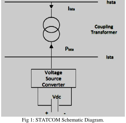
STATCOM, as shown in Figure 1, is a dynamic compensator consists of a set of VSC (voltage source converters) and a coupling shunt‐connected transformer. It is mainly used for power systems dynamic compensation. In fact STATCOM is a static equivalent of a synchronous compensator; however the STATCOM is faster in absorbing or providing reactive power as there is no mechanical moving part involved. In addition the STATCOM offers more control flexibility in comparison with the synchronous machine. The voltage difference across the coupling transformer results in reactive and active power exchanges between the network and STATCOM. The reactive power exchange is achieved by changing the voltage magnitude of voltage source. The active power exchange used to control the DC voltage of the capacitor in steady‐ state operation is zero, neglecting the VSC losses.
Fig 1: STATCOM Schematic Diagram.
III.
UNIFIED POWER FLOW CONTROLLER (UPFC)
Both Static Synchronous Series Compensator (SSSC) and Static Synchronous Compensator (STATCOM) are combined through a DC link forms Unified Power Flow Controller (UPFC) which allows active power flow in both directions between the STATCOM shunt output terminals and SSSC series output terminals. UPFC is controlled to afford compensation of reactive and real series line without an external electric energy source.
Fig. 2: UPFC Schematic Diagram
IV.
SIX BUS TEST SYSTEM
Description of the Transmission System A.
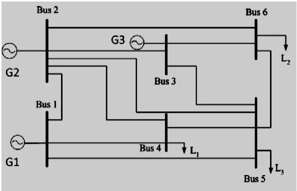
A 6-Bus test system as shown in Fig. 2 is used. The test system consists of three generators and three PQ bus (or load bus). This system which has been made in ring mode consisting of six buses (B1 to B6) connected to each other through single phase equivalent transmission lines. And the constant loads are connected of 70 MW at bus-4, 70 MW at bus-5 and 70 MW at bus-6 and variable dynamic load 30 MW at bus-6 as shown in Fig.3. System has been supplied by three power plants with the phase-to-phase voltage equal to 230 KV.
The voltage sag occurs at bus 6 due to the overloading condition; to mitigate this voltage sag FACTS devices are used. In this paper the STATCOM and UPFC are used to mitigate voltage sag at bus 6, with use of these devices the power flow in the system are also improved.
Fig. 3: The Single Line Diagram Of 6-Bus Test System.
System Analysis With-Out FACTS B.
Fig 4: Simulation of Test System With-Out STATCOM.
Impact of STATCOM C.
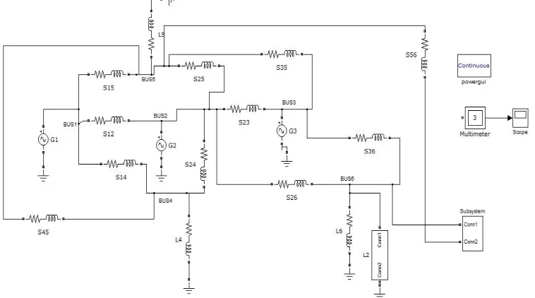
The Static Synchronous Compensator (STATCOM) is one of the key FACTS devices. STATCOM output current (inductive or capacitive) can be controlled independent of the AC system voltage. The power grid consists of two 230-kV equivalents transmission line. The STATCOM is located at bus-6 (B6) and has a rating of +/- 1000 MVA. The simulation diagram is shown in fig 5.
Fig 5: Simulation of Test System with STATCOM.
Impact of UPFC D.
Fig 6: Simulation of Test System with UPFC.
V.
SIMULATION RESULTS
With-out FACTS A.
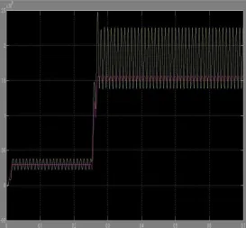
Fig 8: The real and reactive power at bus6 without FACTS
The simulation output of the test system shows the voltage at bus (B4,B5,B6) and power at the bus 6(B6).The yellow colour and pink colour lines represents the active and reactive power at bus 6 (B6) respectively
With STATCOM B.
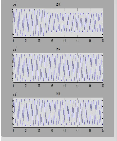
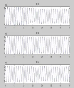
The simulation results for test system with STATCOM are given below. The voltage sag at bus-6 and voltage at bus-4 and bus-5 are shown Fig.9.
With UPFC C.
The simulation results for test system with UPFC are given below. The voltage sag at bus-6 and voltage at bus-4 and bus-5 are shown Fig.10. And also the active and reactive power at bus-6 is shown in Fig.11.
Fig. 10: The Voltage Profile at b-6, b-5, b-4. With STATCOM
Fig 11: The Real And Reactive Power At Bus6 with UPFC
[4] Aarti Rai, Department of Electrical & Electronics Engineering, Chattisgarh Swami Vivekananda Technical University Bhilai, Chattisgarh. Enhancement of Voltage Stability and Reactive Power Control of Multi-Machine Power System Using Facts Devices, “International Journal of Engineering and Innovative Technology” (IJEIT) Volume 3, Issue 1, July 2013.
[5] Anwar S. Siddiqui Tanmoy Deb Jamia Millia Islamia Jamia Millia Islamia New Delhi, India New Delhi, India. Voltage Stability Improvement using
STATCOM and SVC. “International Journal of Computer Applications”. (0975 – 8887) Volume 88 – No.14, February 2014.
[6] Arthit Sode-Yome, Nadarajah Mithulananthan, Member, IEEE and Kwang Y. Lee, Fellow, IEEE. Static Voltage Stability Margin Enhancement Using
STATCOM, TCSC and SSSC. “IEEE/PES Transmission and Distribution Conference & Exhibition”: Asia and Pacific-2005.
[7] Cigre 95 TP108, FACTS Overview, IEEE Power Engineering Society, 1995.
[8] C. A. Canizares, "Power Flow and Transient Stability Models of FACTS Controllers for Voltage and Angle Stability Studies," Proceedings of the 2000