Practical Chip-level Equalizers in HSDPA
Minjae Park, Woonsik Lee, Minh-Viet Nguyen and Hwang Soo Lee
Department of EECS, Division of Electrical Engineering, Korea Advanced Institute of Science and Technology
373-1, Guseong-dong, Yuseong-gu, Daejeon, 305-701, Republic of Korea Email:{mjpark, ecstasy, vietnm}@mcl.kaist.ac.kr, [email protected]
Abstract— High-speed downlink packet access (HSDPA) has been developed to upgrade the current WCDMA system in yerms of providing a higher data rate for mobile users. To ensure a downlink speed of up to 14Mbps, the HS-DPA system has three main features: adaptive modulation and coding, a hybrid automatic repeat request, and fast scheduling. Because standard documents describe only the specifications of Node B, various kinds of HSDPA receivers cen be used with different architectures. An ordinary re-ceiver generally has a rake architecture, though a rake receiver is not good at reducing multiple access interference (MAI). The performance of rake receiver is indispensably deteriorated when the number of mobile users in the system increases. Conversely, an equalizer can alleviate the MAI significantly at the expense of complexity and can therefore be an alternative solution for a rake receiver in a HSDPA system. In this paper, the performance of several equalizers of a HSDPA system is compared in terms of several implementation issues. The simulation results provide useful information about proper equalizers for different design purposes with respect to the performance and complexity trade-off.
Index Terms— WCDMA, HSDPA, equalizer.
I. INTRODUCTION
In a WCDMA system, mobile users can be distin-guished by orthogonal codes assigned by Node B. How-ever, in a high-speed downlink packet access (HSDPA) system, users are not distinguished; rather, an orthogonal code set is used to combine and separate a user’s data frames. In this case, if the code orthogonality is broken by multiple access interference (MAI) caused by multipath fading, multiuser interference, and interference from other cells, the task of restoring the original data is difficult [1]. The performance of a rake receiver is degraded as the number of users increases because the receiver cannot compensate for the effect of MAI, though the symbol energy-to-noise ratio, Es/No, is increased [2]. An equalizer is considered a suitable means of overcoming this problem.
Many studies have focused on equalizers as a way of reducing MAI for better performance in multi-user conditions. In [2], equalizers are used in every finger of a rake receiver structure. Because of the multiple equalizers, the structure is highly complex and too impractical to
This paper is based on ”Performance Comparison of Chip-level Equalizers in HSDPA System” by Minjae Park, Woonsik Lee, Moohong Lee and Hwang Soo Lee, which appeared in the Proceedings of the 40th Annual Simulation Symposium, Virginia, USA, March 2007. c°2007 IEEE.
implement. In addition, the best performance requires prior knowledge of the channel characteristics. In [3], a chip-level equalizer is shown to have many advantages over a symbol-level equalizer. In [4], a conjugate gradient algorithm is applied to obtain the tap weights of the equal-izer, though the structure is unsuitable for application in a HSDPA system due to the high complexity. A fractionally spaced equalizer is another equalizer structure that can enhance the performance of receivers [5]. In CDMA 2000, each data frame has its own pilot symbols. However, in the HSDPA system, a common pilot channel (CPICH) is dedicated to the transmission of reference signals for the receiver. The spreading factor (SF) of a CPICH is different from that of data channels; hence, the task of obtaining a chip-level reference signal for equalization is difficult. It is important, therefore, to find a suitable design structure that enables the equalizer to obtain the reference signal. For this purpose, we introduce two types of equalizers, a block equalizer and an iterative equalizer, the distinguishing feature of which is the method of obtaining tap weights. The block equalizer obtains tap weights with a the Wiener-Hopf equation, whereas, the iterative equalizer obtains exact tap weights by ensuring that the equalized pilot signal track of the original pilot symbol on a chip-by-chip basis. An early study on the performance of a chip-level equalizer is published in [6]. We have made significant extensions to the simulation and practical implementation of a chip-level equalizer. The remainder of this paper is organized as follows: In Section II, we give an overview of the equalizers used in a HSPDA system. To reduce the processing time, we introduced a fixed point structure and applied the structure to some computational complex equalizers. In Section IV, we compare the computational complexity of all the algorithms used in the equalizers. The simulation results are discussed in Section V. Finally, our conclusions are presented in Section VI.
II. EQUALIZERSINTHEHSDPA SYSTEM
accurate channel state information and an additional symbol-by-symbol detector is needed to convert a signal from a chip level to a symbol level. On account of these requirements, we choose not to consider the decision feedback equalizer for the HSDPA receiver. Rather, we focused on the block equalizer and the iterative equalizer for the HSDPA receiver without any channel estimation.
A. Reference Signal
An equalizer needs a known signal as a reference signal. In the HSDPA system, a CPICH is used to transmit a pilot symbol,1 +j, in the signal constellation, and the pilot symbol is regarded as the reference signal.
B. Block Equalizer
A block equalizer solves the Wiener-Hopf equation to obtain the equalizer tap weights. The Wiener-Hopf equation can be written as follows:
Rc=r (1)
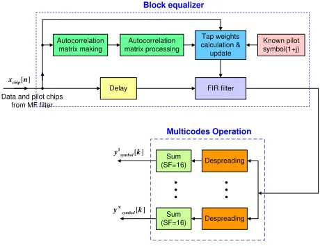
whereRis anN×N autocorrelation matrix,cis anN×1 vector (tap weights), and ris anN×1 cross-correlation vector. With the received signal, the receiver can improve the performance by using windowing methods. Although there are many kinds of windowing methods, we use a decreasing weight method such as the criterion of the recursive least square algorithm (LMS). Thus, if a block is far from the current block, the interference from this block diminishes. Figure 1 shows a block diagram of a block equalizer. We obtained the autocorrelation matrix by using the following equation to compute the autocorrelation of the output signals from the matched filter:
r(k) =E[x(n)x∗(n−k)] =
N X
n=0
x(n)x∗(n−k) (2)
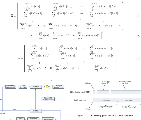
where x(n) is the output from the matched filter. To obtain accurate autocorrelation values, we processed the autocorrelation values with a moving average window. A cross-correlation vector can be formed by taking the correlation between the output of the matched filter and the scrambling data of the pilot symbol 1 +j. We can then calculate the tap weights by solving the Wiener-Hopf equation. The autocorrelation matrix and cross-correlation vector are given by (3) and (4) [4], where d[i] = (1 +j)×scrambling code[i] and T means the transpose of the matrix.
Because of the necessity for real-time processing, the computational complexity of an equalizer should be con-sidered carefully. In the autocorrelation matrix, (3), and the cross-correlation vector, (4), if the number of equal-izer taps is N, then 256×
³ N2−N
2 +N
´
additions and 255׳N2−N
2 +N
´
multiplications are needed to pro-cess one block of the autocorrelation matrix, and 255N additions and256Nmultiplications are needed to process
Delay Autocorrelation
matrix making
Autocorrelation matrix processing
Tap weights calculation & update
Known pilot symbol(1+j)
FIR filter Data and pilot chips
from MF filter
Block equalizer
[ ]
chip
x n
Despreading
Despreading Sum
(SF=16)
Sum (SF=16)
Multicodes Operation
[ ]
N symbol
y k
[ ]
symbol
y1 k
Figure 1. The block diagram of the block equalizer.
the cross-correlation vector. Unfortunately, these compu-tational complexities are greater than the compucompu-tational complexity required to process the equalizer in (1). We therefore need to reduce the computational complexity for the processing of the autocorrelation matrix and the cross-correlation vector. Note that the original autocross-correlation matrix is a Hermitian matrix, and that the values of two adjacent autocorrelation blocks in the autocorrelation ma-trix, namelyP255i=0x[i]x∗[i+1]andP255
i=0x[i+1]x∗[i+2],
are almost the same because only one of the256elements is different. Hence, we can simplify the autocorrelation matrix by assuming that all the diagonal elements have a common value. The autocorrelation matrix can conse-quently be thought of as a Hermitian toeplitz matrix, and the computational complexity of the processing of the autocorrelation matrix and the cross-correlation vector can be reduced significantly. If the autocorrelation matrix is considered to be a Hermitian toeplitz, the matrix can have the form as in (5). To solve the Wiener-Hopf equation, we can use some famous algorithms such as the conjugate gradient algorithm [4], the Levinson-recursion algorithm [7], and the lattice algorithm [8]. All these algorithms can significantly reduce the computational complexity by obviating the need for matrix inversion.
C. Iterative Equalizes
R=
i=255P
i=0
x[i]x∗[i] i=255P i=0
x[i+ 1]x∗[i] · · · i=255P i=0
x[i+N−1]x∗[i] i=255P
i=0
x[i]x∗[i+ 1] i=255P i=0
x[i+ 1]x∗[i+ 1] · · · i=255P i=0
x[i+N−1]x∗[i+ 1] ..
. ... . .. ...
i=255P
i=0
x[i]x∗[i+N−1] i=255P i=0
x[i+ 1]x∗[i+N−1] · · · i=255P i=0
x[i+N−1]x∗[i+N−1] (3) r= · 255 P i=0 x[i]d[i]
255 P
i=0
x[i+ 1]d[i] · · · 255P
i=0
x[i+N−1]d[i]
¸T (4) R=
i=255P
i=0
x[i]x∗[i] i=255P i=0
x[i+ 1]x∗[i] · · · i=255P i=0
x[i+N−1]x∗[i] i=255P
i=0
x[i]x∗[i+ 1] i=255P i=0
x[i]x∗[i] · · · i=255P i=0
x[i+N−2]x∗[i] ..
. ... . .. ...
i=255P
i=0
x[i]x∗[i+N−1] i=255P i=0
x[i]x∗[i+N−2] · · · i=255P i=0
x[i]x∗[i] (5) Despreading (SF=16) Data and Pilot chips
from MF filter
- + Sum (SF=16) Descrambling FIR filter Descrambling / despreading Sum
(SF=256) FIR filter +
Known pliot sysmbol (1+j) Tap weight calculation/update Pilot Data
Figure 2. The block diagram of the iterative equalizer.
the pilot symbol. Hence, a different approach is needed to solve this problem. In [9], a new structure was proposed for the support of a fixed SF of the pilot. Figure 2 shows a block diagram of that structure. The main idea of this system is that the despreading and descrambling after FIR filtering achieves the same result as the despreading and descrambling before FIR filtering. Because the lack reference data is solved, there is no constraint in selecting a suitable algorithm for the FIR filtering. Algorithms for the FIR filter can be a least mean square (LMS) or a square root recursive least square (RLS). The performance of the LMS algorithm is worse than that of the RLS algorithm. However, in contrast to the performance, the computational complexity of the LMS algorithm is less than that of the RLS algorithm. A tradeoff between com-putational complexity and performance should therefore be considered.
III. FIXEDPOINTSTRUCTURE FORANEQUALIZER IN THEHSDPA RECEIVER
When a digital receiver is implemented, a fixed point is often used instead of a floating point to reduce the
32 bit floating-point (IEEE)
32 bit fixed-point
1 bit sign
8 bit exponent (excess 127)
23+1 bit normalized mantissa
IWL Integer Word Length 1 bit sign
integer part fraction part
FWL Fraction Word Length
Figure 3. 32 bit floating point and fixed point structures.
cost and processing time. Figure 3 compares the structure of a floating point and a fixed point. The way that a value is represented in the two structures is completely different. The 32 bit floating point structure can express a value from 2−126 to 2127. In contrast, the 32 bit fixed
TABLE I.
COMPUTATIONALCOMPLEXITY OFFOURTYPES OFBLOCKEQUALIZERS ANDTWOTYPES OFITERATIVEEQUALIZERS
Type of Equalizer Computational Complexity N = 7 N = 15 N = 31 Block Equalizer Conjugate Gradient 257.n2+ 769.5N−1 18003 + 202k 69749 + 794k 271311 + 3130k
(Hermitian) +(3N2+ 8N−1)k
Levinson-Recursion 4N2+ 1023N 7357 16245 35557
(Hermitian Toeplitz)
Latice 2N2+ 1025N−1 7826 22230 92318
(Hermitian Toeplitz) +(3N2+ 8N−1)k
Conjugate Gradient 2N2+ 1025N−1 7272 + 202k 15824 + 794k 33696 + 3130k
(Hermitian Toeplitz) +(3N2+ 8N−1)k
Iterative Equalizer LMS 6N+ 5 47 95 191
Square root RLS 5N2−7N+ 8 204 1028 4596
IV. COMPUTATIONALCOMPLEXITY
Table I shows the computational complexity of each equalizer. Four algorithms in the block equalizers and two algorithms in the iterative equalizers are compared .(In the table, k means an iteration number of the conjugate gradient algorithm and N is the number of taps).
V. SIMULATIONRESULTS ANDDISCUSSION
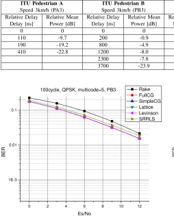
To compare the performance of the equalizers, we used a rake receiver as a reference. In addition, we used square root RLS algorithm for an iterative equalizer and we used a conjugate gradient, a Levinson-recursion, and a lattice algorithms for a block equalizer. The rake receiver had six fingers. All the equalizers and the rake receiver were simultaneously simulated under various conditions to obtain the BER performance. Table II shows the simulation conditions. The channel in the HSDPA system is a frequency-selective fast fading channel. We used four channel models recommended by 3GPP [10]. Table III shows the power delay profiles of these models.
In the first profile, all the equalizers are simulated with 15 taps. For every 256 chips, the tap weights are calcu-lated with different algorithms, and these tap weights are used to filter the input data for the purpose of obtaining the output data. The results are shown in Figs. 4 to 11. In these figures, the curves denoted by FullCG were achieved by using the original Hermitian autocorrelation matrix for the conjugate gradient algorithm, which has a very large computational complexity; and the curves denoted by SimpleCG were achieved by using the simplified Hermi-tian toeplitz matrix for the same algorithm. By using the simplified Hermitian toeplitz matrix, we can considerably reduce the computational complexity without degrading the performance. When the autocorrelation matrix and the cross-correlation vector are generated for the the lattice algorithm and the Levinson-recursion algorithm, the Hermitian toeplitz matrix is used for the equalizer. In channel model PA3, the iterative equalizer, which uses the square root RLS algorithm, reveals no error when QPSK modulation is used. The block equalizer performs better than the rake receiver under all channel conditions. Similarly, the iterative equalizers perform better than the rake receiver, except for the VA 120 channel model. The
TABLE II.
SIMULATIONCONDITIONS
Parameters Values
Multicodes 5 for QPSK / 10 for 16QAM Spreading factor (SF) 256 for pilot / 16 for data
Channel coding no
Channel model PA3, PB3, VA30, VA120
0 2 4 6 8 10 12
1E-3 0.01 0.1
100cycle, QPSK, multicode=5, PA3
B
E
R
Es/No
Rake FullCG SimpleCG Lattice Levinson SRRLS
Figure 4. QPSK modulation, PA3 channel condition.
reason the rake receiver in the VA 120 model performs poorly is because the iterative algorithms such as the LMS or RLS algorithm cannot keep track of the fast variation of channel conditions.
TABLE III.
POWERDELAYPROFILE IN3GPP
ITU Pedestrian A ITU Pedestrian B ITU Vehicular A ITU Vehicular A
Speed 3km/h (PA3) Speed 3km/h (PB3) Speed 30km/h (VA30) Speed 120km/h (VA120)
Relative Delay Relative Mean Relative Delay Relative Mean Relative Delay Relative Mean Relative Delay Relative Mean
Delay [ns] Power [dB] Delay [ns] Power [dB] Delay [ns] Power [dB] Delay [ns] Power [dB]
0 0 0 0 0 0 0 0
110 -9.7 200 -0.9 310 -1.0 310 -1.0
190 -19.2 800 -4.9 710 -9.0 710 -9.0
410 -22.8 1200 -8.0 1090 -10.0 1090 -10.0
2300 -7.8 1730 -15.0 1730 -15.0
3700 -23.9 2510 -20.0 2510 -20.0
0 2 4 6 8 10 12
1E-3 0.01 0.1
100cycle, QPSK, multicode=5, PB3
B
E
R
Es/No
Rake FullCG SimpleCG Lattice Levinson SRRLS
Figure 5. QPSK modulation, PB3 channel condition.
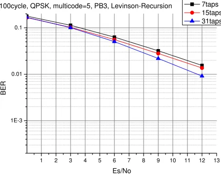
PB3 has the longest delay profile, the results conform exactly with our expectations. In PA3, the shortest tap length (7 taps) performs better than 15 taps and 31 taps. On the other hand, the longest tap length (31 taps) has the best performance in PB3.
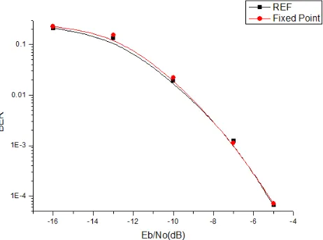
In the last rofile, a fixed-point iterative equalizer with a square root RLS algorithm is simulated. Figure 20 compares the performance of this equalizer with the performance of the floating-point equalizer. In the fixed-point equalizer, the fixed-fixed-point is used for all the re-ceiver components, including the equalizer and the turbo decoder, with a 32 bit fixed-point structure, a 12 point integer part, and a 20 point fractional part. The simulation was performed with a VA 120 channel model, and a multi-code turbo coder/decoder with a single iteration. REF means a floating-point iterative equalizer that uses a square root RLS algorithm. From the figure, the perfor-mance of the fixed-point equalizer is almost same as that of the floating-point equalizer.
VI. CONCLUSION
We compared the performance of several equalizers and a rake receiver in the HSDPA system. The com-putational complexity of the equalizer is higher than that of the rake receiver, but the performance results are much better. Moreover, by using a simplified Hermitian
0 2 4 6 8 10 12
1E-3 0.01 0.1
100cycle, QPSK, multicode=5, VA30
B
E
R
Es/No
Rake FullCG SimpleCG Lattice Levinson SRRLS
Figure 6. QPSK modulation, VA30 channel condition.
toeplitz matrix equation instead of the original Hermitian equation, we can significantly reduce the computational complexity. The block equalizer that uses the simplified Hermitian toeplitz matrix performs almost the same as the equalizer that uses the Hermitian matrix. In the PA3 channel condition, the iterative equalizer outperforms the other type of equalizer and the rake receiver. In the PB3, VA 30, VA 120 channel conditions, the block equalizer shows the best performance. The performance of the block equalizer is always better than that of the rake receiver under all channel conditions because the block equalizer can remove the MAI. The performance of the iterative equalizer is better than that of the rake receiver, except for the VA 120 channel condition. Thus, if a high performance is needed in the HSDPA system, the iterative equalizer can be a good solution. In addition, a 32 bit fixed-point equalizer performs almost the same as a floating-point equalizer, even though it uses a 32 bit fixed-point structure to represent values.
ACKNOWLEDGMENT
0 2 4 6 8 10 12 1E-3
0.01 0.1
100cycle, QPSK, multicode=5, VA120
B
E
R
Es/No
Rake FullCG SimpleCG Lattice Levinson SRRLS
Figure 7. QPSK modulation, VA120 channel condition.
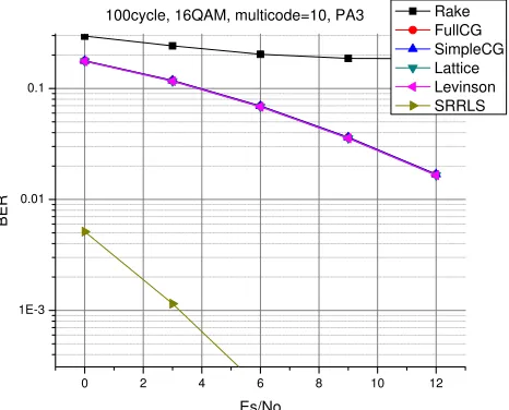
0 2 4 6 8 10 12
1E-3 0.01 0.1
100cycle, 16QAM, multicode=10, PA3
B
E
R
Es/No
Rake FullCG SimpleCG Lattice Levinson SRRLS
Figure 8. 16QAM modulation, PA3 channel condition.
REFERENCES
[1] T. P. Krauss, M. D. Zoltowski, and G. Leus, ”Simple MMSE equalizers for CDMA downlink to restore chip sequence comparison to zero-forcing and RAKE”, ICASSP 2000, vol.5, pp. 2865-2868, Jun. 2000.
[2] M. Latva-aho and M. J. Juntti, ”LMMSE Detection for DS-CDMA systems in fading channels”, IEEE Trans. Comm., vol.48, pp. 194-199, Feb. 2000
[3] T. P. Krauss, W. J. Hillery, and M. D. Zoltowski, ”MMSE Equalization For Forward link in 3G CDMA : Symbol-level Versus Chip-Symbol-level”, Proceedings of the Tenth IEEE Workshop on Statistical Signal and Array Processing 2000, pp. 18-22, Aug. 2000.
[4] S. Chowdhury and M. D. Zoltowski, ”Conjugate gradient based MMSE equalization for DS-CDMA forward link in time-varying frequency selective channels”, GLOBECOM ’01., vol.6, pp. 3390 - 3394.
[5] J. R. Treichler, I. Fijalkow, and C. R. Johnson, ”Fractionally spaced equalizers”, IEEE Signal Processing Magazine, pp. 65-81, May 1996.
[6] M. Park, W. Lee, M. Lee, and H. S. Lee, ”Performance Comparion of Chip-level Equalizers in HSDPA System”,
0 2 4 6 8 10 12
0.15 0.2 0.25 0.3 0.35 0.4
100cycle, 16QAM, multicode=10, PB3
B
E
R
Es/No
Rake FullCG SimpleCG Lattice Levinson SRRLS
Figure 9. 16QAM modulation, PB3 channel condition.
0 2 4 6 8 10 12
0.15 0.2 0.25 0.3 0.35 0.4
100cycle, 16QAM, multicode=10, VA30
B
E
R
Es/No
Rake FullCG SimpleCG Lattice Levinson SRRLS
Figure 10. 16QAM modulation, VA30 channel condition.
Proceedings of the 40th Annual Simulation Symposium, Virginia, USA, Mar. 2007.
[7] M. H. Hayes,Statistical digital signal processing and mod-eling, John Wiley & Sons, Ltd, 1996.
[8] S. Haykin,Adaptive filter theory, 4th edition, Prentice Hall, 2002.
[9] F. Petre, M. Moonen, M. Engels, B. Gyselinckx, and H. De Man, ”Pilot-aided adaptive chip equalizer receiver for in-terference suppression in DS-CDMA forward link”, VTC 2000, vol.1, pp. 303-308, Sept. 2000.
[10] 3GPP. TS 25.101, V7.1.0, User Equipment (UE) radio transmission and reception (FDD), Sept. 2005.
Minjae Park was born in Seoul, Korea in 1980. He received
the B.S and the M.S degree in electrical engineering from Korea Advanced Institute Science and Technology (KAIST), Daejeon, Korea in 2003 and 2006, respectively.
0 2 4 6 8 10 12 0.1
0.15 0.2 0.25 0.3 0.35 0.4 0.45
100cycle, 16QAM, multicode=10, VA120
B
E
R
Es/No
Rake FullCG SimpleCG Lattice Levinson SRRLS
Figure 11. 16QAM modulation, VA120 channel condition.
0 2 4 6 8 10 12
1E-3 0.01 0.1
100cycle, QPSK, multicode=5, PA3, Levinson-Recursion
B
E
R
Es/No
7taps 15taps 31taps
Figure 12. Levinson-recursion equalizer, QPSK modulation, PA3 chan-nel condition.
Woonsik Leewas born in Korea on June 16, 1979. He received
his B.S. in Electronic and Electrical Engineering from Pohang University of Science and Technology (POSTECH), Pohang, Korea, in February 2002 and his M.S.E. in Electrical Engineer-ing from Korea Advanced Institute of Science and Technology (KAIST), Daejeon, Korea, in 2004.
He is currently working towards his Ph.D. at KAIST. His current research interests include digital signal processing, next-generation convergence networks, and Mobile WiMAX systems
Minh-Viet Nguyen was born in Hanoi, Vietnam, in 1980.
He received his B.S. from Hanoi University of Technology (HUT), Hanoi, Vietnam, in 2003 and his M.S. in 2006 from Korea Advanced Institute of Science and Technology (KAIST), Daejeon, Korea, both majoring in Electrical Engineering.
He is currently working towards his Ph.D at KAIST. His research interests include advanced coding and modulation in wireless communication and wireless sensor networks.
Hwang Soo Lee was born in Korea on September 19, 1952.
He received the B.S. in Electronics Engineering from Seoul National University, Seoul, Korea, in 1975 and his M.S.E. and
1 2 3 4 5 6 7 8 9 10 11 12 13
1E-3 0.01 0.1
100cycle, QPSK, multicode=5, PB3, Levinson-Recursion
B
E
R
Es/No
7taps 15taps 31taps
Figure 13. QPSK modulation, PB3 channel condition.
1 2 3 4 5 6 7 8 9 10 11 12 13
1E-3 0.01 0.1
100cycle, QPSK, multicode=5, PB3, Levinson-Recursion
B
E
R
Es/No
7taps 15taps 31taps
Figure 14. QPSK modulation, VA30 channel condition.
Ph.D. in Electrical Engineering from Korea Advanced Institute of Science and Technology (KAIST), Daejeon, Korea, in 1978 and 1983, respectively.
0 2 4 6 8 10 12 1E-3
0.01 0.1
100cycle, QPSK, multicode=5, VA120, Levinson-Recursion
B
E
R
Es/No
7taps 15taps 31taps
Figure 15. QPSK modulation, VA120 channel condition.
0 2 4 6 8 10 12
1E-3 0.01 0.1
100cycle, 16QAM, multicode=10, PA3, Levinson-Recursion
B
E
R
Es/No
7taps 15taps 31taps
Figure 16. 16QAM modulation, PA3 channel condition.
0 2 4 6 8 10 12
0.15 0.2 0.25 0.3 0.35
100cycle, 16QAM, multicode=10, PB3, Levinson-Recursion
B
E
R
Es/No
7taps 15taps 31taps
Figure 17. 16QAM modulation, PB3 channel condition.
0 2 4 6 8 10 12
0.1 0.15 0.2 0.25 0.3 0.35
100cycle, 16QAM, multicode=10, VA30, Levinson-Recursion
B
E
R
Es/No
7taps 15taps 31taps
Figure 18. 16QAM modulation, VA30 channel condition.
0 2 4 6 8 10 12
0.1 0.15 0.2 0.25 0.3 0.35
100cycle, 16QAM, multicode=10, VA120, Levinson-Recursion
B
E
R
Es/No
7taps 15taps 31taps
Figure 19. 16QAM modulation, VA120 channel condition.