R E S E A R C H A R T I C L E
Open Access
Stress shielding effects of two prosthetic groups
after total hip joint simulation replacement
Chengdong Piao
1, Dankai Wu
2,4*, Min Luo
2and Hongshun Ma
3Abstract
Objective:The study aims to compare the stress shielding effects of implantable anatomical and traditional prostheses afterin vitrototal hip joint replacement simulation. The study serves as a biomechanical basis for novel artificial prostheses and for clinical hip joint replacements.
Methods:Sixteen femoral specimens from adult male corpses were randomly divided into two groups: the traditional prosthesis group implanted into femur specimens using simulated total hip joint replacement (n= 8) and the femoral neck-preserved anatomical prosthesis implantation group that used a collum femoris preserving stem/trabeculae oriented pattern (CFP/TOP) acetabular cup (n= 8). The strain values in the two groups before and after prosthesis implantation were measured at different test points using electric resistance strain gauges. The stress shielding rate was calculated according to the related formula.
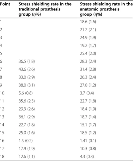
Results:The results showed that the rates of proximal femoral stress shielding were significantly higher at test points 1–10 in the traditional femoral prosthesis transplantation group than in the anatomical prosthesis group (p< 0.05). Conclusions:There were different effects of stress shielding between the anatomical and traditional prostheses. Retained femoral anatomical implants should reduce stress shielding and increase the stability of anatomical prosthesis implants.
Keywords:Hip joint, Artificial prosthesis, Replacement, Electric measurement
Introduction
Although total hip joint simulation replacement has been considered to be the most successful and influential ortho-pedic surgery of the twentieth century, short prosthesis life is its fatal flaw. Important factors, including the prosthesis design, installation, materials, and others, can influence the lifespan of the prosthesis [1]. Femur bone remodeling and bone loss continue after hip replacement surgery, es-pecially in the proximal femur. After replacement, the stress shielding of the proximal femur is considered to be the mechanical cause of bone loss. Bone loss and cortical thinning eventually lead to joint prosthesis failure [2]. Studies on the stress shielding effect, after prosthesis im-plantation, have been receiving increased attention. Glo-bally, researchers have studied the biomechanics of the
hip joint and the stress shielding effects of artificial pros-theses [3-7]. The results of anin vitrobiomechanical ex-periment [8] confirmed that the lateral alar process of the stem reduces the stress shielding of the medial proximal femur and greatly increases the rotational stability of the stem in the medial bone cement sheath. Using the finite element method, Fouad [9] suggested that a subtle change in the artificial femoral head material can influence hip joint stress distribution; this phenomenon is mainly re-lated to the elastic modulus of the artificial femoral head material. Beulah et al. [10] assessed a novel, low-elastic modulus prosthesis with a hexagonal cross-sectional de-sign, using the finite element method and found that it is more effective in reducing stress shielding and in strength-ening prosthesis fixation. Davis et al. [11] established a fi-nite element analysis model, after reconstruction and replacement with a metal hip joint surface, and simulated the force to calculate stress values. After reconstruction and replacement with a metal hip joint surface, the stress was mainly concentrated inside the femoral neck and at * Correspondence:[email protected]
2
Department of Orthopedics, China-Japan Union Hospital, Jilin University, Changchun, Jilin Province 130031, China
4
Department of Orthopaedics, China-Japan Friendship Hospital, Jilin University, Changchun, Jilin Province 130031, China
Full list of author information is available at the end of the article
the junction of the prosthesis and neck head; stress shielding occurred at the lower bony part of the fem-oral prosthesis.
Studies on the stress shielding effect, after total hip joint simulation replacement, focused on implanting dif-ferent prostheses, mostly using the three-dimensional finite element method [8-11]. Studies that compare the stress shielding effects of two types (anatomical and traditional) of artificial prostheses, based on electric strain gauge measurement values before and after total hip joint simulation replacement, are lacking. In bio-mechanical research, the use of a strainmeter is a meas-urement technique for studying the stress shielding effect, after the implantation of various prostheses by total hip joint replacement simulation.
This study simulated total hip arthroplasty using nor-mal, adult cadaver femurs. The measurement of electric strain was estimated before and after prosthesis place-ment using German retained prosthetic femoral neck-type and traditional prostheses. The strain, stress, and stress shielding rate values for each point were measured in the femur, under compressive stress, before and after placement of the prosthesis, comparing the retained femoral neck-type and the traditional prosthesis groups. We aimed to provide a biomechanical basis for novel artificial prostheses and clinical hip joint replacements by performing a quantitative comparative analysis of the effects of retained femoral neck prostheses and trad-itional prostheses implanted into femur specimens using electric strainmeter measurements.
Materials and methods Specimens
A total of 16 femoral specimens from normal adult male corpses (age range, 20–30 years old; height range, 1.75– 1.82 m; weight range, 74–85 kg (mean, 80 kg)) were pro-vided by the Department of Anatomy, Bethune Medical University (Changchun, China). Within 2 h after death, the left and right femurs were removed, packed with normal saline-soaked gauze, placed into plastic bags, sealed, and stored at−20°C. This study was conducted in accordance with the declaration of Helsinki. This study was conducted with approval from the Ethics Committee of China-Japan Friendship Hospital, Jilin University.
Grouping
Before the experiment, the femoral specimens were thawed at room temperature. A total of 16 specimens (8 left and 8 right femurs) were randomly divided into two groups. In the traditional prosthesis group (n = 8), the prosthesis (Vatallium; Beijing Prussia Explant Material, Beijing, China) was implanted into the femur specimens using a total hip joint replacement simulation (Figure 1).
In the femoral neck-preserved anatomical prosthesis group (n= 8), the collum femoris preserving stem/trabeculae ori-ented pattern (CFP/TOP) acetabular cup (titanium alloy; Waldemar LINK GmbH & Co. KG, Hamburg, Germany) was used (Figure 2).
Femoral size measurement and embedding immobilization method
The length and diameter of the femoral specimens were measured using a steel ruler and a reading microscope, respectively. In the traditional femoral prosthesis group, the specimens were 366.4–428.8 mm long and 25.81– 26.92 mm in diameter. In the anatomical prosthesis group, the femurs were 375.4–439.8 mm long and 25.82–27.32 mm in diameter. Before artificial prosthesis implantation, the femur specimens were 370.2–376.3 mm long and 25.81–27.32 mm in diameter. Leveling of the surface of the lower ends of the femurs was achieved by embedding immobilization, using diluted dental base acrylic resin powder at the lower end of each specimen. The lower end of each femur was placed in a mold, and the mold was filled with denture base resin powder and liquid (Shanghai New Century Dental Material, Shanghai, China) (powder/liquid ratio, 22 g:10 mL) to embed and fix the distal ends of the specimens.
Electric measurements using strain gauges
To conduct electric measurements, gum-based, foil-type electric resistance strain gauges (Huangyan Testing In-strument Factory, Taizhou City, China) were affixed to the femurs in each group before prosthesis implantation in both groups. The length, resistance value, and sensitivity coefficient of the gauges were 2 × 2 mm, 120 ± 0.1Ω, and 2.12, respectively. According to the requirements of the strain gauges, the adhesion positions were cleaned using al-cohol and acetone before femoral prosthesis implantation. The strain gauges were affixed using Speedglue 502 (Beijing Chemical Works, Beijing, China) at various measurement points. Subsequently, the specimens were allowed to dry naturally for 24 h. A schematic of the electric resistance strain gauge placement at various femoral measurement points is shown in Figure 3.
Strain electric measurements in pre-transplant normal femurs in the traditional and anatomical prosthesis implant groups
used, and the temperature compensation was external. A compression load of 0.8 kN (average weight of young males in northern China) was applied using the univer-sal testing machine at an experimental velocity of 2 mm/min (static load), and the strain values at various measurement points were measured using a yj-4501A model static resistance strain gauge (Nanjing Univer-sity of Aeronautics and Astronautics, Nanjing, China).
Femur implantation methods for the traditional and anatomic femoral prosthesis groups
After strain electric measurements of the normal fem-oral specimens in the traditional and anatomic pros-thesis groups, the specimens were frozen at−22°C for 24 h and then thawed at room temperature. The prostheses were implanted into the normal femoral specimens of both groups. The method for implanting the prostheses into the femurs of the traditional group was described by Liu et al. [12]. The implantations were performed by the same, highly qualified surgeon. The femoral joint was fixed on to the platform. The osteotomy was per-formed, 1.5 cm from the top of the small trochanter to the bottom of a large trochanter, using a clinical saw to remove the femoral head and most of the neck. Cancel-lous bone excavation was then performed within the distal femur to determine the location of the marrow cavity. The marrow cavity was expanded using a clinical
reamer to reach the distal femur marrow cavity, along the great trochanter, and any internal debris was re-moved. The appropriate prosthesis was selected for bio-logical fixation of the femoral neck to maintain an incline of 10°–15°.
The method for implanting the prostheses into the fe-murs of the anatomic prosthesis group was performed according to the method of Liu et al. [12]. The femurs were fixed on the operating platform, and the osteotomy was performed, vertically, to the femoral neck, under the femoral head. The outside line of the osteotomy was often 1.5 cm away from the great trochanter, and re-moved the femoral head. The aperture in the center of the large trochanter was opened, and the marrow cavity was expanded using a clinical file to obtain the proper thickness and curvature. The prosthesis was positioned, tightly fixing the prosthesis neck collar to the neck cortex.
Strain gauge adhesion and measurement methods for both prosthesis groups
The strain values of each measuring point in the two groups were obtained by affixing the strain gauge to the pre-transplant normal femur specimens in each group after transplantation. The strain electrical measurements were obtained for the normal femurs in the traditional and anatomic prosthesis implantation groups.
Stress values and stress shielding rate calculation method Under compression loading, the femurs mainly under-went pressure and bending. The stress analysis showed that both the pressure and bending acted on the femur axis. Therefore, the resistance strain gauge was adhered to the femur axis to measure the strain stress values at each measuring point, and calculations were performed using Hooke’s law [13] (σ=E⋅ε, where, σ represents stress, and εrepresents strain; the E-modulus for elasti-city, is also called the macroscopic Young’s modulus). The stress values were calculated according to the elastic modulus of 17.6 GP, measured during the preliminary testing prior to this study. The implanted femurs in both prosthesis implantation groups were measured according to the stress shielding rate formula (η= 1−σ/σ0× 100 %,
whereηrepresents the stress shielding rate, andσ andσ0
are the stress values for the femurs in the same position before and after implantation of the normal femurs) [14].
Statistical analysis
Measurement data were expressed as means ± SD. Data analyses were performed using SPSS, version 16.0, soft-ware (SPSS, Chicago, IL, USA). The differences between the data, from the two groups, were compared using single factor analysis of variance and the Scheffe law;p< 0.05 was considered to indicate statistical significance.
Results
The results of the stress measurements at the different test points before and after traditional and anatomic femoral prosthesis implantations are shown in Table 1. The stress shielding rates are shown in Table 2. Accord-ing to the differences in geometry and elastic modulus between the anatomical and traditional prostheses, the stress shielding rate of the anatomical prosthesis was lower than that of the traditional prosthesis when im-planted into the femur specimens. Femoral electric strain measurements of the normal control group, the traditional prosthesis implantation group, and the
Figure 2Schematic of electric resistance strain gauge distribution of femoral specimens.Measurement points 1, 2, 3, 4, and 5 were in the femoral neck area. Measurement point 4 was in the medial femoral neck at the upper 3 cm of the lesser trochanter; measurement point 3 was at the upper 1.5 cm of the lesser trochanter; measurement point 6 was at the transverse middle position of lesser trochanter; measurement point 8 was at the rear of measurement point 6; measurement point 7 was at the opposite side of the lower lesser trochanter; measurement point 9 was at the opposite side of the femoral neck; measurement point 10 was at the lower 1 cm of the lesser trochanter; measurement points 11, 12, 13, and 14 were stem tip positions of the anatomical prosthesis implantation group; and measurement points 15, 16, 17, and 18 were stem tip positions of the traditional prosthesis implantation group.
anatomical prosthesis implantation group are presented (Figure 3A,B,C). Strain measurement was performed using electronic universal testing machine and imaged by resist-ance strain gauges (Figure 3D).
The study aims to compare the stress shielding effects of implantable anatomical and traditional prostheses afterin vitrototal hip joint replacement simulation. The study serves as a biomechanical basis for novel artificial prostheses and for clinical hip joint replacements.
Discussion
The study aims to compare the stress shielding effects of implantable anatomical and traditional prostheses after in vitro total hip joint replacement simulation. Com-pared to the traditional prosthesis group, there was a lower stress shielding rate in the proximal 1–10 stations in the femoral neck dissection-type prosthetic femur specimens in the anatomical femoral prosthesis group (p< 0.05). In the anatomical model, the stress shielding rate, under a load, was lower than the rate in the
small trochanter seriously undermined the metaphyseal cancellous bone system, changing the balance of power among the systems and the stress distribution at the upper end of the normal femurs. Once prosthesis is inserted femoral intramedullary, normal stress distribu-tion of proximal femur will be changed. Stress will be spread to distal femur via intramedullary prosthesis despite the stress should be supported by proximal femur, which leads to stress shielding in proximal femur [15,16]. This resulted in the stress shielding rate of the anatomic femoral prosthesis implantation group being lower than that of the traditional femoral prosthesis implantation group, and suggested that a proximal, geo-metric design of the prosthesis, with a low elastic modu-lus, was essential. An unreasonable design would be to increase the chance of loosening the proximal. The bio-mechanical effects of the prosthetic materials were also critical. Prosthesis rigidity was related to the elastic modulus and to the cross-sectional area and shapes of the materials, but the stress shielding effect of the pros-thesis stem, being bulky and rigid, was not necessarily strong because the stress shielding was a result of many factors working together. The relationship of degree of matching of the proximal end was closer. Only an elastic material with an elastic modulus closer to cortical bone
could reduce the stress shielding effect, and prosthesis with different materials and shapes lead to different ef-fects of stress shielding [17]. The high elastic modulus of prosthetic material resulted in serious stress shielding following femoral transplantation; therefore, a low elastic modulus material is a better choice for prostheses.
Kim et al. [18] compared an anatomic femoral pros-thesis with common biological fixation and found that the proximal anatomic prosthesis was a better match to the canal anatomy, whereas the distal prosthesis was bet-ter than biological fixation. Thus, the proximal segment had better stress conduction. The finer, remote structure not only avoided excessive flexion stiffness but also con-tacted the distal cortical bone, thereby reducing the stress shielding rate. Liu et al. [12] simulated total hip arthroplasty and studied the viscoelasticity of the femur and the prosthesis by inserting the retained prosthetic femoral neck-type prosthesis (from Germany) and a traditional prosthesis (from Beijing Prussia Iron and Steel Research Implants, Beijing, China). They found that the traditional prosthesis group, by removing the femoral head and femoral neck, largely damaged the femoral longitudinal interface of the bone marrow, allowing bone moisture to be lost. The collagen and elastic fibers were largely damaged, which led to reduced
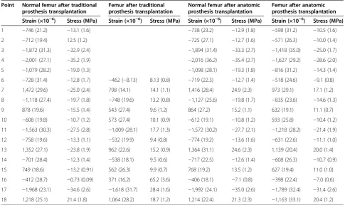
Table 1 Strain electric measurements of each group (values are represented in mean (SD)) (n= 8)
Point Normal femur after traditional prosthesis transplantation
Femur after traditional prosthesis transplantation
Normal femur after anatomic prosthesis transplantation
Femur after anatomic prosthesis transplantation
Strain (×10−6) Stress (MPa) Strain (×10−6) Stress (MPa) Strain (×10−6) Stress (MPa) Strain (×10−6) Stress (MPa)
1 −746 (21.2) −13.1 (1.6) −738 (23.2) −12.9 (1.8) −598 (31.2) −10.5 (1.6)
2 −712 (19.4) 12.5 (1.2) −725 (27.1) −12.7 (1.6) −571 (26.3) −10.0 (1.4)
3 −1,872 (31.3) −32.9 (2.4) −1,894 (31.4) −33.3 (2.7) −1,418 (35.0) −25.0 (1.7)
4 −2,001 (27.1) −35.2 (1.9) −2,016 (36.2) −35.4 (2.7) −1,627 (29.2) −28.6 (2.0)
5 −1,079 (28.2) −19.0 (1.3) −1,098 (28.1) −19.3 (1.8) −816 (31.2) −14.3 (1.4)
6 −728 (31.4) −12.8 (1.7) −462 (−8.13) 8.13 (0.8) −719 (22.3) −12.7 (1.4) −518 (24.6) −9.1 (0.8)
7 1,472 (29.6) −25.0 (2.4) 798 (14.1) 14.1 (1.1) 1,416 (28.4) 24.9 (2.3) 973 (29.1) 17.1 (1.2)
8 −1,118 (27.4) −19.7 (1.8) −748 (19.6) 13.2 (0.8) −1,127 (25.6) −19.8 (1.7) −835 (23.6) −14.6 (1.3)
9 878 (19.6) −15.5 (1.4) 543 (27.4) 9.6 (1.2) 864 (27.2) 15.2 (1.1) 632 (19.1) 11.1 (0.7)
10 −608 (19.8) −10.7 (1.2) 573 (27.4) 10.1 (0.9) −612 (19.1) −10.8 (1.2) 593 (25.8) −10.4 (1.2)
11 −1,563 (30.3) −27.5 (2.8) −1,009 (28.1) 17.7 (1.3) −1.572 (30.2) −27.7 (2.1) −1,218 (28.2) −21.4 (1.9)
12 −758 (19.6) −13.3 (1.1) −532 (19.9) 9.4 (0.8) −774 (19.2) −13.6 (1.6) −631 (22.6) −11.1 (1.0)
13 1,352 (27.1) −23.8 (1.9) 962 (22.6) 15.2 (0.9) 1,364 (31.1) 24.6 (2.3) 1,139 (20.4) 20.0 (1.4)
14 −701 (28.4) −12.3 (1.4) −538 (18.1) 9.5 (0.6) −717 (22.5) −12.6 (1.4) −608 (26.3) −10.7 (0.9)
15 749 (18.6) −13.2 (0.91) 562 (26.3) 9.9 (0.7) 768 (19.2) 13.5 (1.2) 627 (19.4) 11.0 (1.0)
16 −412 (28.7) −0.73 (0.09) 371 (16.2) 65.2 (3.6) −406 (18.1) −7.1 (0.8) −398 (22.4) −7.0 (0.6)
17 −1,968 (23.1) −34.6 (2.6) −1,618 (31.7) 28.4 (1.6) −1,992 (24.1) −35.0 (2.6) −1,789 (32.4) −31.4 (2.6)
18 1,218 (25.1) 21.4 (1.8) 1,064 (28.2) 18.7 (1.2) 1,214 (22.4) 21.3 (2.3) −1,163 (33.1) 20.4 (1.2)
The strain values of 6, 7, 9, 10, 11, 12, 14, 15, 16, and 18 measurement points in the reservation and traditional femoral prosthesis groups were analyzed by paired
ttest; the difference was significant (p< 0.05). 1, 2, 3, 4, and 5 traditional measuring points were destroyed and cannot be measured. Experimental results showed that the strain values of 6, 7, 9, 10, 11, 12, 14, 15, 16, and 18 measurement points in the traditional prosthesis group were less than those of the Germany femoral neck retention prosthesis group (p< 0.05).
7,200-s rising displacement quantity and a change in the inherent rheological characteristics. The 7,200-s rising displacement quantity was more than that in the trad-itional prosthesis group, because the femur neck was retained with less damage to the intramedullary canal. According to these findings, they concluded that the retained femoral neck-type of prosthesis design, from Germany, conformed to biomechanical principles. In the present study, the parameters or methods, including the simulated total hip arthroplasty, used two kinds of pros-thesis, but the prosthesis implantation methods, test specimen stress, and the applied load were similar to those used by Liu et al. [12].
Although the experiment was carried out differently than those of [18] and [12], the results showed that fem-oral prosthesis implantation played a role in reducing stress shielding under compressive loads, consistent with a previous report [12]. This indicates that stress distribu-tion in the proximal femur, after anatomic femoral pros-thesis implantation, changed less than during traditional femoral prosthesis replacement. Thus, the femoral stress shielding rate, under compression loads, was reduced.
The experimental results supported previous reports [18] suggesting that closer matching of the anatomic state of the proximal anatomic prosthesis to the medullary cavity and proximal segment matching resulted in good conduction of stress to reduce the stress shielding rate.
Walker et al. [19] reported that the femur stress level was closer to normal bone after bone cement prosthesis replacement. For uncemented prosthesis, the femoral moment of the compressive strain is 56% of the normal value but only 30% of that for cemented prostheses. The compressive strain and rod-end strain in an uncemented prosthesis are 135% and 109% of the normal values, re-spectively, whereas they are 151% and 115%, respect-ively, of the cemented prostheses. Herein, the study supports a biological fixation method for the artificial prostheses. Engh et al. [20] performed a quantitative analysis of femoral bone resorption caused by stress sheltering. They found that bone mineral density, on the fixed prosthesis side, was significantly lower than that on the contralateral side and that bone loss was most obvi-ous in the metaphyseal area. On average, 45% of osteo-porosis patients, after receiving an artificial prosthesis, showed increased stress shielding in the greater trochan-ter of the femur and the femoral moment area and an increased concentration of stress in the rod-end area than before replacement. The findings in the study sug-gested that the region of most stress shielding was the proximal femur. Therefore, this region should receive careful attention during the selection and design of arti-ficial prosthesis and prior to the surgical placement of an artificial prosthesis.
Under the premise of achieving stability, the design of artificial prostheses should involve the selection of low-modulus elastic fibers that are resistant to friction and that can be designed into artificial joints that can be placed into medullary cavity, causing the least damage to the femur. The consistency of the angle after placement of the designed artificial joints and the physiological angle of hip joint, matching the artificial prosthesis with the femur, can avoid looseness and improve the effect.
The present experiment was conductedin vitro, which may influence the experimental results and be different from the situation created during a clinical hip replace-ment. The advantages of strain electrical technique in an in vitro experiment and an in vivo animal experiment are that they can indicate the characteristics of field measurements, and the determinations can be directly performed during internal fixation operations. The elec-trometric method only measures point-by-point strain on the surface of the specimen, but does not measure the full stress distribution in a specimen. The main rea-son is that certain areas in the strain gauge wire grid lead to limitations in understanding stress distribution in specimens and only measure the average strain in the
Table 2 Stress shielding rate calculations (values are represented in mean (SD)) (n= 8)
Point Stress shielding rate in the traditional prosthesis group (η%)
Stress shielding rate in the anatomic prosthesis group (η%)
1 18.6 (1.6)
2 21.2 (2.1)
3 24.9 (1.9)
4 19.2 (1.7)
5 25.4 (2.0)
6 36.5 (1.8) 28.3 (2.4)
7 43.6 (2.6) 31.4 (2.8)
8 33.0 (2.9) 26.3 (2.4)
9 38.0 (3.1) 27.0 (1.2)
10 5.6 (0.8) 3.7 (0.4)
11 35.6 (2.3) 22.7 (1.8)
12 29.3 (2.6) 18.4 (1.9)
13 36.1 (2.9) 18.7 (1.4)
14 22.7 (1.8) 15.1 (1.7)
15 25.0 (1.6) 18.5 (1.2)
16 1.5 (0.2) 1.41 (0.1)
17 17.9 (1.9) 10.3 (0.8)
18 12.6 (1.1) 4.3 (0.3)
area. The experimental data show some discreteness be-cause of the limited number of samples and the inherent differences between biological materials. Due to the un-evenness of some parts of the upper femur specimens, it was difficult to adhere the strain gauges to allow the meas-urement of strain in the three directions and compute the angle of the principal stress. These types of measurements should be considered in future in-depth studies.
Taken together, different effects of stress shielding can be found between the anatomical and traditional pros-theses. Retained femoral anatomical implants can in-crease the stability of anatomical prosthesis implants and reduce stress shielding.
Conclusions
The anatomical and traditional prostheses had different stress shielding effects. The effect of the femoral neck-preserved anatomical prosthesis implant was significant.
Competing interests
The authors declare that they have no competing interests.
Authors’contributions
DW designed the study. ML performed the study. HM analyzed the data. CP wrote the paper. All authors read and approved the final manuscript.
Acknowledgements
This study was supported by the Science and Technology Key Problem of Jilin Province, China (20110492).
Author details
1Department of Orthopaedics, The Second Hospital of Jilin University, Changchun, Jilin Province 130041, China.2Department of Orthopedics, China-Japan Union Hospital, Jilin University, Changchun, Jilin Province 130031, China.3Department of Engineering Mechanics, College of Mechanical Science and Engineering, Jilin University, Changchun, Jilin Province 130022, China.4Department of Orthopaedics, China-Japan Friendship Hospital, Jilin University, Changchun, Jilin Province 130031, China.
Received: 17 December 2013 Accepted: 22 July 2014 Published: 30 August 2014
References
1. Luo ZP, Dai M:The research on the influence of total hip prosthesis design and installation on joint movement.Orthop J China2005, 13:778–781.
2. Dan D, Germann D, Burki H, Hausner P, Kappeler U, Meyer RP, Klaghofer R, Stoll T:Bone loss after total hip arthroplasty.Rheumatol Int2006, 26:792–798.
3. Mújica Mota RE:Cost-effectiveness analysis of early versus late total hip replacement in Italy.Value Health2013,16:267–279.
4. Liaw CK, Wu TY, Hou SM, Yang RS, Shih KS, Fuh CS:Computerized ellipse method for measuring acetabular version after total hip replacement—a precision study using synthetic and real radiographs.Comput Aided Surg
2013,18:195–200.
5. Randelli F, Banci L, Ragone V, Pavesi M, Randelli G:Effectiveness of fibrin sealant after cementless total hip replacement: a double-blind randomized controlled trial.Int J Immunopathol Pharmacol2013,26:189–197. 6. Keurentjes JC, Blane D, Bartley M, Keurentjes JJ, Fiocco M, Nelissen RG:
Socio-economic position has no effect on improvement in health-related quality of life and patient satisfaction in total hip and knee replacement: a cohort study.PLoS One2013,8:e56785.
7. McNamara BP, Cristofolini L, Toni A, Taylor D:Relationship between bone-prosthesis bonding and load transfer in total hip reconstruction.
J Biomech1997,30:621–630.
8. Sangiorgio SN, Ebramzadeh E, Longjohn DB, Dorr LD:Effects of dorsal flanges on fixation of cemented total hip replacement femoral stem.
J Bone Joint Surg Am2004,86:813–820.
9. Fouad H:In vitro evaluation of stiffness graded artificial hip joint femur head in terms of joint stresses distributions and dimensions: finite element study.J Mater Sci Mater Med2011,22:1589–1598. 10. Beulah P, Sivarasu S, Mathew L:Design optimization of skeletal hip
implant cross-sections using finite-element analysis.J Long Term Eff Med Implants2009,19:271–278.
11. Davis ET, Olsen M, Zdero R, Papini M, Waddell JP, Schemitsch EH: A biomechanical and finite element analysis of femoral neck notching during hip resurfacing.J Biomech Eng2009,131:10021–10028. 12. Liu GY, Zhang Q, Jin Y:Stress and strain analysis on the anastomosis site
sutured with either epineurial or perineurial sutures after simulation of sciatic nerve injury.Neural Regeneration Research2012,7(29):2299–2304. 13. Liu GY, Jin Y, Li P:Investigation of creep mechanical characteristics of
femoral prostheses by simulated hip replacement.Exp Ther Med2013, 5:1189–1193.
14. Li YF, Wang YJ, Du WM:Stress difference on femur after total hip replacement.J Med Biomech1996,11:140–143.
15. Richmond BJ, Bauer TW, Stulberg BN:Boner mineral density in patients undergoing uncemented THA.Calcif Tissure Int1990,46:145.
16. Sumner DR, Galante JO:Determinants of stress shielding: design versus materials versus interface.Clin Orthop1992,274:202–206.
17. Harris WH:Will stress shielding limit the longevity of cemented femoral components of total hip replacement?Clin Orthop1992,247:120–125. 18. Kim YH, Kim JS, Cho SH:Strain distribution in the proximal human femur.
An in vitro comparison in the intact femur and after insertion of reference and experimental femoral stems.J Bone Joint Surg Br2001, 83:295–301.
19. Walker PS, Schneeweis D, Murphy S:Strains and micro motions of press-fit femoral stem prostheses.J Biomech1987,20:693–702.
20. Engh CA, McGovern TF, Bobyn JD:A quantitative evaluation of per prosthetic bone remodeling after cement less total hip arthroplasty.
J Bone Joint Surg Am1992,74:1009–1020.
doi:10.1186/s13018-014-0071-x
Cite this article as:Piaoet al.:Stress shielding effects of two prosthetic groups after total hip joint simulation replacement.Journal of Orthopaedic Surgery and Research20149:71.
Submit your next manuscript to BioMed Central and take full advantage of:
• Convenient online submission
• Thorough peer review
• No space constraints or color figure charges
• Immediate publication on acceptance
• Inclusion in PubMed, CAS, Scopus and Google Scholar
• Research which is freely available for redistribution
Submit your manuscript at www.biomedcentral.com/submit