DESIGN AND ANALYSIS OF LOADING
AND UNLOADING CARS AND BIKES IN
CONTAINER USING LEAD SCREW
SYSTEM
Dr.T.VENKATAMUNI
1Professor, Dept. of Mechanical engineering Jeppiaar institute of technology, Chennai
India, PIN:631604 [email protected]
ARJUN BALAJI
Student, Dept. of Mechanical engineering Jeppiaar institute of technology, Chennai
India, PIN:631604
ABSTRACT
The paper deals on vehicle caring containers and its loading and unloading method. How the vehicle must be handled during the loading and unloading time. We design a new method called as lead screw method in which a loading unloading mechanism is used to overcome difficulties in conventional methods and make the handling process simple and better than other method. The objective is to allow a wide variety of vehicles to be efficiently containerized. They are many methods available in vehicle caring container like R-Rake system etc., But by using our lead screw system method it maximises the number of vehicles that can be safely loaded into one container by raising and securing vehicles into the roof space. The Lead screw is mostly preferred for linear motion power transfer. So the lead screw system with rack is used to lift the cars and bike inside the container with the help of servo motor, spur gear and bevel gear the lead screw will rotate and lift the load on rack. The column with lead screw will work with half nut mechanism to fix the rack with load at a certain height.
Key words – loading time, labour effort, and safety.
I. INTRODUCTION
The Product manufacturing in an industry tends to transport their products to a distant place are the nearer agents or to the market. The loading and unloading of a product plays one of the vital role in an industry. The challenges in loading and unloading are comes with size and weight are the number of products etc. The transportation of a product should be safely end to the destination place to satisfy the customers. There are many methods been practiced to load and unload different products manufactured at different places. So to make this process safe and secure our lead screw method is more economical and helpful. In industries they are many equipment and methods are available for primary material handling like fork lift, skip hoist, conveyor etc. Are used but in vehicle loading purpose they are mostly use labour for handling because they only handle the material with care. So to reduce the labour work our lead screw method is best and suitable for vehicle transport container. With less labour cost, less loading time and more safety can be achieved by implementing our system in containers.
2. LITERATURE REVIEW:
1. Ayachi LACS, ENIT, Tunis-Belvédère Tunisie International Journal of Computer Applications - In this paper they tell about how to utilize the yard space properly in shipping to improve the caring capacity according to size, dimension and delivery date and place they decide the container placement.
2. “Design of Lead Screw Mechanism for Vertical Door Wrapping Machine”- this journal says about the design procedure and the nomenclature of lead screw and also says about analysis of lead screw using work bench software.
3. Linear Motion Systems” ME EN 7960, Precision Machine Design- this tells about the why lead screw is best for linear motion power transfer when compare to belt, gear and chain drives.
4. “The Dynamics of Lead-Screw Drives: Low-Order Modeling and Experiments” -they says about the load acting on the screw during static and dynamic condition and the application and benefits.
2.1.METHODS AND COMPARISION
They are many design of containers available based on the application they are 20th and 40th feet dry container, 20th and 40th feet flat rack container, open top container, refrigerated container etc. So that the length, width and height of the container is also change. But our concept is to make the single container into the multipurpose container used for all application.
According to the specification of car or bike they select the suitable container and the loading methods. They are many methods,
• Fixed rack method - the rack is fixed so the major problem is we need to load the vehicle in upper rack using wood slab.
• Using wood - here the major problem is the wood work inside the container is done by labour on the time of loading so its time taking process.
• Semi and complete Knock down - In this method the complete dismantle of car or bike is done for safe transport, so here the separate team is required to assemble the part.
• R-Rack system - this system allow 2car for loading in 20ft container the loading is safe and secure but it is not suitable for bike and other goods.
Table 1 - Comparison between methods
2.3. LEAD SCREW DESIGN AND WORKING
It is also called as power screw is a device which convert the rotational motion to a linear motion and transmit power. Usually square, acme and buttress thread form are generally used as lead screw. There is a large contact area between male and female thread of lead screw so power transmit is also high without noise and result is large frictional loss is occurred. Due to this friction losses the lead screw will having very less efficiency but generally self-locking. In self-locking locking lead screw, the load can’t lower itself without any external force. So this feature is generally used to hold the load. This self-lock is done by the helix angle in the lead screw if the angle cross above the 45degree it loss the self-lock ability it moves according to the load.
The nut is constrained from rotating with the screw, so as the screw is rotated the nut travels back and forth along the length of the shaft. The friction on the nut is a function of environment, lubrication, load, and duty cycle therefore, practical life cycle is difficult to quantify. Lead screw/nut drive systems are available in a variety of sizes and tolerances. Contact is primarily sliding, resulting in relatively low efficiency and a wear rate proportional to usage.
feet dry container Load capacity max - 28000 kg
flat rack container Load capacity max - 30000 kg Open top container Load capacity max - 24000 kg Refrigerated container Load capacity max - 24000 kg
Fig 1 - Nomenclature of lead screw
3.1.DESIGN OF SCREW
Creo is a family or suite of design software supporting product design and it was developed by PTC (parametric technology corporation). Creo runs on Microsoft Windows and provides apps for 2D design, 3D CADparametric featuresolid modelling, 3D direct modelling, Finite Element Analysis and simulation, schematic design, technical illustrations, and viewing and visualization.
Fig 2 and 3 Front and Isometric view of Lead Screw
3.2. ANALYSIS OF SCREW
Ansys is used for both 2d and 3d analysis is was mainly developed for aerospace and nuclear industries where the safety of structure is critical. This software is now used of finite element and structural analysis of a product by separating the components into small element and the analysis is done and the result is comesunder the any form like deformation, stress and thermal etc. For analysis we use ANSYS 14.5 software package. In that ansys workbench is used for stress anddeformation analysis of lead screw. In the time of import the file in the STPorIGES format. When during analysis the column is attached with lead screw because the load will transfer to the column and the impact on lead screw is reduce.
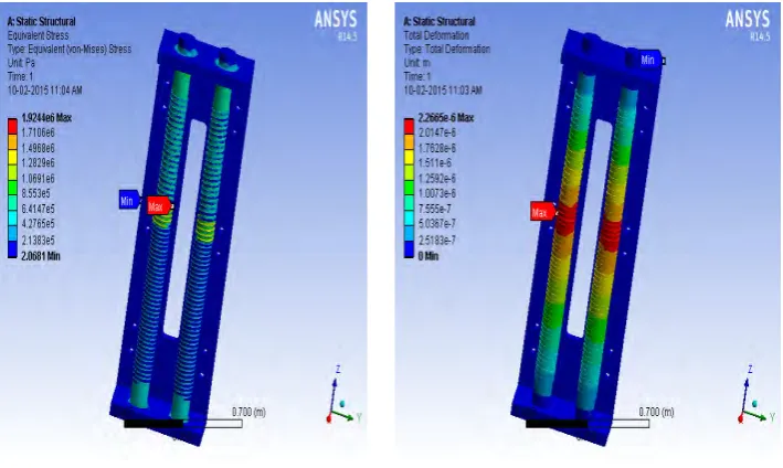
Fig 4 and 5 Stress Analysis Result, Deformation Analysis
Table 2 - Analysis result
4.1. WORKING OF LEAD SCREW SYSTEM
The working of lead screw system comprises of lift the rack upward and downwards for loading and unloading purpose. The mechanism used in our project is half nut mechanism. The half nut splits into two half with an internal square threads which tends to hold the rotating lead screw to move the rack. The half nut has a slot which is the place for the handle bar helps for the engage and the disengaging of the half nut form lead screw. The half nut with the handle is placed in the column. Before loading, the rack is at the floor of the container, once the vehicle is loaded in the rack and lash the tires with the belts for safety purpose. The labor will operate the servo motor with the help of switches. Then the motion of the lead screw will done by the gears
Fig 6 - Whole assembly
Once using the handle of half nut we engage the two half of nut to the rotating lead screws. Then rack is connected to the half nut is moves corresponding to the movement of the half nut. After reaching the required height the movement will be stopped at that place by turn off the switching control of the motor.
S.no Parameter Values
1. Maximum Stress 1.9244e6 pa (or) 1.9244 N/mm2
2. Minimum Stress 2.0681 pa (or) 2.0681*10-6 N/mm2
3. Max Deformation 2.2665e-6 m (or) 2.2665e-3 mm
4.2 DESIGN FORMULA AND PARAMETER
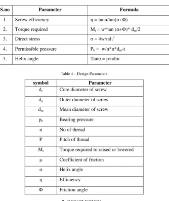
Table 3 – Design Formulas
Table 4 – Design Parameters
5. CONCLUSION
The Final conclusion states that the modelling of loading and unloading of cars and bike using lead screw system designed and fabricated successfully with replacing disadvantages faced using the previous methods discussed in the report and the main advantage of using this method is to reduce the loading and unloading time, safe moving of products and the reduced manpower used for loading and unloading.
And finally the future of this method can be widely extend by the above suggested materials discussed in the scope of future delivers the way to increase the efficiency of the lead screw system for loading and unloading in containers.
REFERENCE
[1] Ayachi et.al (2012), Harmony search to solve the container storage problem with different container types, International Journal of
Computer Applications, Vol.48 (22), pp 26-32
[2] MehulV.Gohil, Jignesh Patel (2014), Design of Lead Screw Mechanism For Vertical Door Wrapping Machine, International Journal
for Scientific Research & Development, Vol. 2(4),pp. 185-189.
[3] Ivan Sunit Rout et.al (2014), Design and Fabrication of motorized automated Object lifting jack, IOSR Journal of Engineering
(IOSRJEN) Vol. 04(5), pp. 6-12.
[4] Luzenira et.al. (2014) International Journal of Latest Research in Science and Technology Volume 3(5), pp. 140-144.
[5] Precision Machine Design, “Linear Motion Systems” ME EN, ppt.
[6] Thomason Neff, www.danahermotion.com, Length limitation: lead screw catalogue
[7] Trans-rak international ltd removable car racking system.
[8] Kripa K. Varanasi , The Dynamics of Lead-Screw Drives: Low-Order Modeling and Experiments
[9] Webpage: http://www.helixlinear.com/LinearLibraryItem/ helix_lead_screw_reference_chart
S.no Parameter Formula
1. Screw efficiency η = tanα/tan(α+Ф)
2. Torque required Mt = w*tan (α+Ф)* dm/2
3. Direct stress σ = 4w/пd12
4. Permissible pressure Pb = w/n*п*dm*t
5. Helix angle Tanα = p/пdm
symbol Parameter
dc Core diameter of screw
do Outer diameter of screw
dm Mean diameter of screw
pb Bearing pressure
n No of thread
P Pitch of thread
Mt Torque required to raised or lowered
μ Coefficient of friction
α Helix angle
η Efficiency