ENHANCED IMAGE TRANSMISSION
USING ITERATIVE DENOISING
ALGORITHM COMBINED WITH
TURBO CODES
*1
M. Srinivasa Rao, *2Dr.P.Rajesh Kumar, #3Ajesh Kumar Viswanadham, #3Nagarjuna Katta,
*1
Professor, Department of ECE, Sir..C.R.R.Engineering College, Eluru. AP, India
*1
*2
Professor & HOD, Department of ECE, PVP Siddhartha institute of technology, Vijayawada, AP, India
*2
#3
Post Graduate students, Sir.C.R.R.Engineering College, Eluru. AP, India
#3
{ajeshkumar.palakol, [email protected]}
Abstract:
The constraints on bandwidth, power, and time in many image communication systems prohibit transmission of uncompressed raw image data. Compressed image representation, however, is very sensitive to bit errors. In this Paper, a new scheme combining the Techniques of Iterative Denoising algorithm and Turbo Codes is introduced. For image compression, Bitplane Slicing is used in which the original image is partitioned into 2N quantization levels, where N is denoted as bit planes. Then each of the N-bit-plane is coded by Turbo encoder and transmitted over Additive White Gaussian Noise (AWGN) channel. At the receiver side, bit-planes are re-assembled. Each of the noisy bit-plane values of the image is evaluated iteratively using an Iterative Denoising Algorithm and Turbo decoder. This System has extra-ordinary satisfactory results of both Bit Error Rate (BER) and image enhancement performance for -1 dB Signal-to-Noise Ratio (SNR) values, compared to traditional turbo coding scheme and 2-D filtering, applied separately. Hence, it is concluded that this new algorithm combined with turbo codes, Bitplane Slicing results in an excellent way of image compression along with reduced bit error rate even in noisy channel transmission.
Keywords:
Bitplane Slicing, Neighborhood relationship, Turbo Codes, RSC encoder, Iterative Denoising Algorithm, Image Compression.
Introduction:
Application of a channel code is required before transmission of data over noisy channel for increased reliability. In order to encode an Image they are represented in digital format in a wide variety of ways for comfortable processing and transmission using Digital Techniques. The main aspects to be considered during transmission of an image are Bandwidth requirement and the effect of noise during transmission. But, compressing an image may lead to the degradation of its quality and at the receiver conventional filtering techniques used to eliminate noise may also affect the image. Bitplane Slicing technique is an efficient method of compressing an image and an iterative process of decoding the image using turbo codes along with Iterative Denoising Algorithm, considering the Stochastic Properties and Neighborhood relation between the pixels, results in a better way of image transmission. Turbo Codes make it possible to attain a better bit error rate performance and robust transmission even in a noisy channel transmission.
1. System Model
Algorithm, turbo decoder followed by a Hard Decision, and image combiner sections as shown in Fig.1. For the input image, binary correspondence of each pixel amplitude value is grouped in bit-planes. Then these bit planes are turbo encoded and transmitted. At the receiver, a combined structure, denoted as Denoising Algorithm-Turbo decoder is employed. Denoising Algorithm-Algorithm-Turbo decoder is an iterative structure with a feedback link from the second Turbo decoder and Iterative Denoising Algorithm filtering. The decoding process continues iteratively till the desired output is obtained. The advantage of Stochastic Properties and neighborhood relation of pixels is taken into account in Denoising Algorithm scheme. Although each bit slice is transmitted in serial way, the bit string is reassembled at the receiver to preserve the original neighborhood matrix properties before decoding process. Thus instead of classical serial bit stream communication and decoding, in the proposed scheme, the coordinates of the pixels are kept as in their original input data matrix. Each pixel value is mapped to corresponding binary N-level and their binary correspondences are mapped regarding to the quantization of the transmitted bit slices.
Fig.1: System Model 2. Bit Plane Slicing/ Re-assembling
Highlighting the contribution made to the total image appearance by specific bit plays an important role in compression of an image. This is the basic principle involved in Bitplane Slicing. In digital image representation each pixel is represented by number of bits. The number of bits required to represent each pixel depends on the greylevels identified in the image. The number of bitplanes is equal to the number of bits represented for each pixel.
Fig.2: Bitplanes Representation
For the importance of data rate, it is not needed to take into consideration all the slice contributions some planes can be ignored until the changes in gray level have an acceptable impact on the image. This approach will increase the data rate up to (N-1) times, by only transmitting most important significant bitplanes. Thus proposed bit slicing can be an efficient way of compression technique. To obtain more accurate 2D images, other bits can also be transmitted.
Maximum resolution is obtained if all the bit slices from most significant to least significant are decoded at the receiver side without sacrificing resolution. Note that the most significant bit plane contains visually significant data. The other bit planes contribute to more subtle details in the image Bit plane
Re-assembling is the reverse process of the slicing. The planes are recombined in order to reconstruct the image. At the receiver, after each bit slice is decoded and hard decision outputs are formed, then all bit slice plane outputs are reassembled as first it from the first bit slice, second bit from the second bit plane, the most significant bit from the last bit slice. Then these binary sequences are mapped to corresponding amplitude value of the pixel. In the case of compression, due to the resolution, not all the bits but some of them can be taken into account and corresponding quantized amplitude values of the pixels are found.
3. Turbo Codes
Turbo codes are capable of achieving a bit error rate of 10-5 at a channel signal-to-noise ratio (SNR) 0.7 dB, an improvement of almost 2 dB compared to the best previously known codes.
Fig.3: Turbo Encoder
The decoding algorithm involves the joint Estimation of two Markov processes (MAP) one for each constituent code. The goal of the MAP algorithm is to find the a posteriori probability of each state transition, message bit, or code symbol produced by the underlying Markov process. Because the two Markov processes are defined by the same set of data, the estimated data can be refined by sharing information between the two decoders in an iterative fashion. The output of one decoder can be used as a priori information by the other decoder as shown in Fig.4. The iteration process is done until the outputs of the individual decoders are in the form of hard bit decisions. In this case, there is not any advantage to share information anymore.
Consider a half-rate RSC encoder with M memory size. If the dkis an input at time k, the output X kis equal,
k k
X
=
d
(1)Remainder r(D) can be found using feedback polynomial g(0) (D) and feed forward polynomial g(1) (D) . The feedback variable is,
K
(0)
i k k j j
j 1
r
d
r g
−=
=
+
(2)and RSC encoder output Y k which is as called parity data is given as
K
(1)
k k j j
j 0
Y
r g
−=
=
(3)RSC encoder with memory M=2 and rate R=1/2 which feedback polynomial g(0) = 7 , feed forward polynomial
g(1) = 5 and it has a generator matrix
( )
(
2) (
2)
G D 1,
=
1
+ +
1 D
/ 1 D
+ +
D
(4)where D is memory unit.
4. Iterative Denoising Algorithm
The new unsupervised iterative algorithm, called as Denoising Algorithm uses the advantage of stochastic properties and neighborhood relations between the cells of the input image. In Denoising Algorithm scheme; first regarding to the stochastic properties of the data, all possible quantization levels are determined and then 2D input image is processed using a function, based on averaging and neighborhood relationship and after that, a parameter P is assigned to each cell. Then Gaussian probability values are mapped to each cell regarding to all possible quantization levels and the attended value P. A maximum selector defines the highest probability value for each cell. In the case of complex data, first iteration output is fed into input until a sufficient output is found. This algorithm has iterative and cellular characteristics. First of all, neighborhood parameters in matrix P are computed. For a cell, the output values of the neighbor cells, Pi,j, are multiplied by
some weights, summed and then averaged according to the weights. This can be formulized for the first level neighborhood of any Nth bit plane as,
2
( ) ( 1)
, ,
1
1
1
.
8
(
,
)
(1
)
j b i b t t k l b i jk i b l j b
z
C
Max k i l
j
z
C
+ + − = − = − =
=
−
−
+
(5)Here i and j are row and column indexes, t is iteration index, b is the level of neighborhood which effects the cell and maximum is an operator which finds out the maximum of the values in the parenthesis in the case of the conditions below.
0,
(
,
)
0,
1
0
k i if k i
l
j and k i
Max k i l
j
l
j
l
j if l
j
k i and l
j
if k i
l
j
−
− ≥ −
− ≠
−
− = −
−
− ≥ −
− ≠
− = − =
(6)b can take any integer value and this designates the neighborhood dimension. At the first iteration ( t = 1), P(t −1)
indicates the cells of the input image. Level of neighborhood and this effect can be shown as,
2
1
,
1...
z
z
m
z
image. To calculate the color probability of the cells, logarithmic form of Gaussian probability is used. Weighted average is computed before calculating the color probability of the cells.
Quantization levels are obtained from the image according to the color level. These quantization levels are chosen from the colors which are encountered in the image. The color probability of the cells is defined as,
(8)
Here l is quantization index, qlshows the quantization or color level and σ2 is the variance of the noise. Then,
maximum probabilities are chosen and hence, pixel color is set.
5. Simulation Results
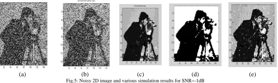
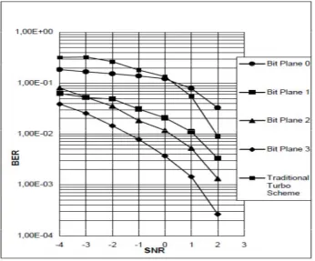
In this section, simulation results are presented that illustrate the performance of the proposed Denoising Algorithm over the transmitted image. In simulation, ½ rate RSC encoder with AWGN channel model is used. Here the generator matrix is g=[111:101], a random interleaver is applied and the frame size is chosen as N=150. Iteration number (between Denoising Algorithm and decoder) is taken 1. At first, the pixels of the image are converted to 16 gray levels and then sliced to four bit-planes. All planes are then coded via RSC encoder and a random interleaver. The coded planes are corrupted with SNR=-1dB, +1dB and 2dB and transmitted. Fig. (5-7) show the corrupted, traditional turbo processed, Denoising Algorithm processed and reconstructed images via total system. The results have shown that, to recover the corrupted image at 1 dB SNR or below, the well known image-processing and conventional Turbo algorithms are not satisfactory as seen in Fig. (5-7). The proposed system gives good results from -1 dB SNR to 2 dB as shown in Fig. 8.
(a) (b) (c) (d) (e)
Fig.5: Noisy 2D image and various simulation results for SNR=-1dB
(a) Corrupted image with SNR=-1dB (b) Turbo processed image (c) Denoising Algorithm processed image (d) Most significant part of Denoising algorithm & turbo codes output (e) Denoising algorithm & turbo codes processed image
(a) (b) (c) (d) (e)
Fig.6: Noisy 2D image and various simulation results for SNR= +1dB
(a) (b) (c) (d) (e)
Fig.7: Noisy 2D image and various simulation results for SNR=+2dB
(a) Corrupted image with SNR= +2dB (b) Turbo processed image (c) Denoising Algorithm processed image (d) Most significant part of Denoising algorithm & turbo codes output (e) Denoising algorithm & turbo codes processed image
As a result, obtaining good results depend on the local neighborhood relations of the planes. Increasing the number of the bit planes enables to study with more detailed images. If the image does not have detail information, it is no need to increase the number of the bit planes. To increase the number of the bit planes means to improve the complexity. In Fig. (4d-6d), it is clearly seen that it is possible to extract main characteristics of original image from most significiant part of total system output.
Fig. 8: Bit error performance of conventional Turbo and Turbo along with Denoising Algorithm with various bit planes 6.Conclusion
7.References
[1] L. R. Bahl, J.Cocke, F.Jelicek and J. Raviv, “Optimal decoding of linear codes for minimizing symbol error rate”, IEEE Trans. On Information Theory, pp.284-287, March 1974.
[2] J. Hagenauer and P. Hoeher, “A Viterbi Algorithm with Soft-Decision Outputs and its Applilcations”, Proceedings of GLOBECOM” 89, Dallas, Texas, pp. 47.1.1-47.1.7, November 1989.
[3] W. Koch and A. Baier, “ Optimum and sub-optimum detection of coded data disturbed by time-varying inter-symbol interference,” proceedings of IEEE Globecom,pp.169-1684, December 1990.
[4] J. A. Erfanian, S. Pasupathty and G.Gulak, “Reduced compexity symbol detectors with parallel structures for ISI channels,” IEEE Trans. Communications, vol.42,pp. 1661-1671, 1994.
[5] P. Robertson, E. Villebrun and P. Hoeher, “A comparision of optical and sub-optimal MAP decoding algarithms operating in the log domain”, Proc. Intern. Conf. Communications(ICC), pp. 1009-1013, june1995.
[6] C. Berrou, A. Glavieux and P.Thitimajshima, “Near Shannon limit error-correcting coding and decoding: Turbo codes”, Proc. Inter. Conf. Communications(ICC), Geneva, Switzerland, pp.1064-1070, May 1993.