© IJEDR 2018 | Volume 6, Issue 3 | ISSN: 2321-9939
IJEDR1803026
International Journal of Engineering Development and Research (
www.ijedr.org
)
144
Static Analysis On Wing Spar Joint For An Aircraft
Using Finite Element Method
1Pavan G, 2Manjunath M V
Assistant Professor, Don Bosco Institute Of Technology, Bangalore
_____________________________________________________________________________________________________
Abstract - Aircraft is a highly complex flying structure which undergoes various stresses duringoperation. Generally transport aircraft undergoes nominal manoeuvring flights. During take-off and landing, wing produces maximum lift and it undergoes highest bending moment. The bending moment will be maximum at the root of the wing. The bending moment and shear loads from the wing are transferred to the fuselage through the attachment joints. This paper deals with stress analysis of wing spar joint. The stress analysis was carried out for wing-spar joint using Finite Element Method (FEM). Prediction of the fatigue life of wing-spar joint in a transport aircraft was precisely made. The proposed aircraft structure uses materials such as Heat Treated AISI-4340 for T section joint and Aluminum Alloy– 2024-T351 for I-section wing spar and rivet joints. Fatigue life calculation was carried out for typical service loading condition using constant amplitude S-N data for various stress ratios and local stress at various stress concentration. In this work estimation of fatigue life for crack initiation of spar jointstructure were carried out at maximum stress location.
Keywords - Finite element approach, stress analysis, C clamp joint structure, static analysis, fatigue analysis.
_____________________________________________________________________________________________________
1. INTRODUCTION
Now a days the stress analysis and fatigue life[1] prediction for spar joint in an aircraft wing using finite element method.
The use of finite element method (FEM) for the estimation of fatigue life has been proved as a good alternative to the experimental method [1]. The main function of the wings in aircraft is to provide lift. The wings have been classified as two
essential parts, the internal wing structure consists of spars, ribs, stringers, and the external wing structure consists of skin. Spar is a heavy beam in which different transverse shear load and shear bending is acting on the spar beam. It usually consists of thin panel (web) with a cap or flange at the top and bottom. Ribs are also used in the span wise distribution. The work undertaken at present incorporates the outline and investigation of the flight part utilizing the variable loads located on the spar. Normally, in aircraft the outline is done by dividing the spars into two sections. The investigation is done by utilizing the FEM packages MSC NASTRAN and MSC PATRAN. AL2024-T351 material is used in this analysis. It is found that the maximum stress is induced are within allowable limits. Additionally in the basic part the fatigue failure is generated due to high tensile stress acting on the critical region, a necessary fatigue calculation is carried out on the maximum stress. The fatigue damage value is found within the critical damage, thus assuring the validity of a design.
Schematic diagram of two wing spar joint
2. METHODOLOGY
IJEDR1803026
International Journal of Engineering Development and Research (
www.ijedr.org
)
145
Flow chart of a static load analysis 3. GEOMETRICAL CONFIGARATION
The spar is modeled in CATIA as shown in bellow figure. It consists of different structures. , spar is considered as one of the major component in the wing. Usually spar is used as a lifting capacity of the aircraft. Majority of the weight is acting on the spar usually spar is attached to the ring and one end of the spar is connected to the fuselage and other end is act as a free edge, so an obtained spar is a cantilever beam. Each part is modeled in CATIA software. The wing spar joint with finite element properties is shown in bellow figure.
Design of uniform spar
The spar is modeled in CATIA as shown in Fig.6. It consists of different structures. , spar is considered as one of the major component in the wing. Usually spar is used as a lifting capacity of the aircraft. Majority of the weight is acting on the spar usually spar is attached to the ring and one end of the spar is connected to the fuselage and other end is act as a free edge, so an obtained spar is a cantilever beam. Each part is modeled in CATIA software. The wing spar joint with finite element
properties is shown in bellow figure.
© IJEDR 2018 | Volume 6, Issue 3 | ISSN: 2321-9939
IJEDR1803026
International Journal of Engineering Development and Research (
www.ijedr.org
)
146
Finite element model of spar joint 3.1. Chemical Composition
The Al 2024-T351 is used in current spar joint due to high strength and fatigue resistance properties. The chemical composition of Aluminium (Al) alloy and the physical properties of Al alloy are shown in Table.1 and Table.2.
Table 1 Chemical composition of Al alloy
COMPONENT Wt. %
Al 90.7-94.7
Cr Max 0.1
Cu 3.8-4.9
Fe Max 0.5
Mg 1.2-1.8
Mn 0.3-0.9
Other, each Max 0.05
Other, total Max 0.15
Si Max 0.5
Ti Max 0.15
Table 2 Physical properties of Al alloy
Young’s Modulus 7000 kg/mm2
Poisson’s Ratio 0.3
Density 2800 kg/mm3
Yield strength 28 kg/mm2
Ultimate strength 47kg/mm2
4. LOADS ON THE WING BOX
IJEDR1803026
International Journal of Engineering Development and Research (
www.ijedr.org
)
147
Table 3 Span length and load distribution of spar joint
4.2 Static analysis of spar beam using 1-D
Static analyses of spar joint by using 1D in N/mm2 Deformation of spar joint by using1D analysis.
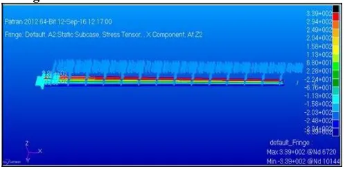
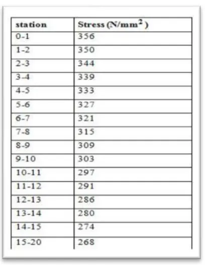
The static analysis is carried out by using analysis software (MSC software). The maximum stress is found to be 356 N/mm2.
However, the tensile yield strength of the aluminum 2024-T351 is 362 MPa. The induced stress level is found to be less than the allowable stress limit of the material used in the design of spar joint by using 1-D analysis. Hence, the static analysis of spar joint is considered to be safe design. Table 4.2 details the result summary of the static analysis of the spar joint using 1-D analysis.
4.3 Static analysis of spar beam using 2-D
© IJEDR 2018 | Volume 6, Issue 3 | ISSN: 2321-9939
IJEDR1803026
International Journal of Engineering Development and Research (
www.ijedr.org
)
148
Deformation of spar beam by using 2D analysisThe maximum stress is found to be 339 N/mm2. However, the tensile yield strength of the aluminium 2024-T351 is 362 MPa.
The induced stress level is found to be less than the allowable stress limit of the material used in the design of spar joint by using 2-D analysis. Hence, the static analysis of spar joint is considered to be safe design. Table 4.3 details the result summary of the static analysis of the spar joint using 2-D analysis.
4.4. Local Analysis Results
As in the case of global analysis, the particular area considered for local analysis undergoes tension in bottom skin. In order to create the same surrounding, we constrain any one or two translation direction, hence we took two cases.
Case 1: With z translation constraint
Case 2: With x and z translation constraint
The directions are given to the rivets
The maximum stress is found at the one end of the rivet location, near to the bottom flange the obtained value is 327 N/mm2.
However, the tensile yield strength of the aluminium 2024-T351 is 362 MPa. The induced stress level is found to be less than the allowable stress limit of the material used in the design of spar joint by using 2-D analysis. Hence, the static analysis of spar joint is considered to be safe design.
Static analysis of spar joint using 2-D Maximum stress is obtained at 1 end of the rivet location
The maximum stress is found at the one end of the rivet location, near to the bottom flange the obtained value is 327 N/mm2.
However, the tensile yield strength of the aluminium 2024-T351 is 362 MPa. The induced stress level is found to be less than the allowable stress limit of the material used in the design of spar joint by using 2-D analysis. Hence, the static analysis of spar joint is considered to be safe design
4.5. Summary of Results for Iteration
IJEDR1803026
International Journal of Engineering Development and Research (
www.ijedr.org
)
149
Table 5 Result summary of the static analysis of the spar joint using 2-D analysis.
Table 6 Element and nodes used in C clamp joint
Parts of the
spar joint Type of element Number of
Number
of Aspect elements nodes ratio
Top flange Quadrilateral element 576 689 5 web Quadrilateral element 1920 2068 5 Bottom flange Quadrilateral element 480 3729 5
rivet Bar 64 22 5
© IJEDR 2018 | Volume 6, Issue 3 | ISSN: 2321-9939
IJEDR1803026
International Journal of Engineering Development and Research (
www.ijedr.org
)
150
It is the vital step towards the design of the aircraft wing, Calculating SFD and BMD is one of the bases of analyzing beams and cantilever. Because of shear force diagram and bending moment diagram helps in design of every parameter namely spar etc. figure 4.1 shows the span wise load distribution the table 4.1 shows the span length and load distribution which helps in determining the maximum bending stress.Table 6 Span length and load distribution of spar joint
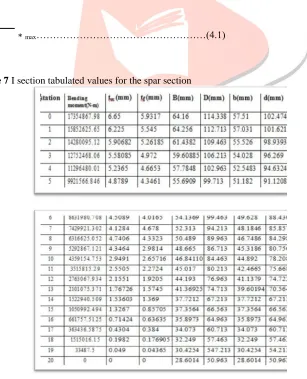
The following cantilever beam also indicates the different bending moment at different cross sections also the I sections values are tabulated in table 7. The bending stress values for each stations is calculated bellow
Bending moment
σb =
∗ max………(4.1)
BD3−bd3/12
IJEDR1803026
International Journal of Engineering Development and Research (
www.ijedr.org
)
151
bending moment diagram of tapered shear force diagram of tapered 6. FINITE ELEMENT ANALYSIS RESULTS
The FEM results show that the stress values which are calculated through software are given below, by taking average value of stress values at a distance of 4875 mm from the applied load is 308.1522731kg.
Maximum stress is obtained at 1 end of the rivet location
The maximum stress is found at the one end of the rivet location, near to the bottom flange the obtained value is 327 N/mm2.
However, the tensile yield strength of the aluminium 2024-T351 is 362 MPa.
7. CONCLUSION
In the present work, the finite element analysis is carried out on the wing spar joint by considering light jet aircraft structure, using MSC NASTRAN/PATRAN software. From the Static analysis, it is found that for the 1-D analysis the maximum stress obtained is 350 N/mm2, which is well within the allowable stress of the material so an obtained design is considered to be safest
design. From the Static analysis, it is found that for the 2-D analysis maximum stress obtained is 346 N/mm2, which is well
within the allowable stress of the material so an obtained design is considered to be safest design. From the Static analysis, it is found that the maximum stress obtained at one end of the rivet location is 327 N/mm2, so the maximum stress obtained is not
exactly the allowable stress of the material so obtained design is considered to be safest design.
REFERENCES
[1] Aleksandar grbovic and Bosko rasuo, “FEM based exhaustion break development forecasts for fight of lightaircraft under variable plentifulness stacking”, 1st International Conference on Structural Integrity, ICONS-2014
[2] Nagarjun C M, Nagaraj V C, Byrareddy and K E Girish, “Stress Examination of Flat Tail Joint of a Vehicle Air ship and Fatigue Life Estimation”, IJSRD - International Journal for Scientific Research & Development| Vol. 3, Issue 04, 2015 | ISSN (online): 2321-0613
[3] [3 ] Rhys Jones, Daren Peng, Pu Huang, Raman R. K. Singh, “Break development from normally happening material discontinuities in operational air ship”, 3rd international conference on material and component performance under variable
amplitude loading, VAL 2015.
[4] R.M. Ajaj , M.I. Friswell , M. Bourchak , W. Harasani, “Range transforming utilizing the GNATSpar wing”, aeronautics and astronautics, university of Southampton, S0171BJ,UK.
[5] Harish E.R.M1, Mahesha.K2, Sartaj Patel3, “ stress analysis of an wing attachment bracket for an transport aircraft structure”, Vol. 2, Issue 7, July 2013
© IJEDR 2018 | Volume 6, Issue 3 | ISSN: 2321-9939
IJEDR1803026
International Journal of Engineering Development and Research (
www.ijedr.org
)
152
[7] Polagnagu James*, Kotresh Gaddikeri , Byji Varughese and M. Subba Rao, "realization of an ideal wing test structure of anidelaised wing box”, 1st International Conference on Structural Integrity, ICONS-2014 Ralph l stephens , Ali fatemi , Robert r stephens , Henry o fuchs, “metal weariness in designing”,
[8] Mohamed Hamdan A1, Nithiyakalyani S2, “ design and analysis of an wing and spar of the swept back