IJEDR1702132
International Journal of Engineering Development and Research (www.ijedr.org)794
POWER QUALITY IMPROVEMENT BY VOLTAGE SAG MITIGATION
AND REACTIVE POWER COMPENSATION USING STATCOM
THROUGH ARTIFICIAL NEURAL NETWORK ALGORITHM
J.R.LYDIA JENIFER
1, M.PORKODI
21M.E. Scholar, Depart ment of EEE, Sona College of Technology, Sale m-636 005, Ta milnadu, India. 2Associate Professor, Depart ment of EEE, Sona Co llege of Technology, Sale m-636 005, Ta milnadu,
India.1jrlydia jenife r@g ma il.co m, 2mpporkodi@g mail.co m
Abstract—Microgrids are becoming increasingly attractive to c onsumers as it allows utilizati on of e asily avail able rene wable energy sources. They are usually installe d at consumer’s sites i.e the distribution end. Due to high saturation of distri bute d generation units with di fferent types of loads, microgri ds can cause power quality issues. Some of the m are voltage swells and sags, and low power factor which fur ther re quire reac ti ve power compensation. This paper presents the utilization of the custom power de vice s pecifically S TATCOM in mitigating the pr oble m of voltage sags occurring i n microgri d. The perfor mance of STATCOM, installed in microgri d, is analyze d for reacti ve power compe nsation to overc ome these concerne d issues. The design of a neur al network controller using voltage as fee dback for significantly improving the dynamic per for mance of converter . The per for mance is analyze d wi th the hel p of neur al network contr oller and the simulati on studies have de monstrate d the e ffecti ve influence of the STATCOM on the improve ment of the voltage using MATLAB/Simulink.
Keywords—Micr ogrid,Ne uro c ontroller, Re acti ve power compensation,STATCOM, Voltage sag
I. INTRODUCTION
Power quality is defined as the interaction of electrica l power with electrica l equip ment. If electrica l equipment operates correctly and reliably without being damaged or stressed, then the electrical power is good quality. On the other hand, if the electrical equip ment ma lfunctions and is damaged during normal usage, then the power quality is poor.
As a general, any deviation from norma l of a voltage source can be classified as a power quality issue. Power quality issues can be very high-speed events such as voltage impulses, high frequency noise, waveshape faults, voltage swells and sags and total power loss. All type of electrica l equipment will be affected differently by power quality
issues. By analyzing the electrical power and evaluatin g the equipment or load, power quality proble m is determined..
The power quality can be monitored by installing a special type of high-speed recording test equipment to monitor the electrica l power. Th is type of test equipment will provide information used in evaluating if the electrical power is of sufficient quality to reliably operate the equipment. Monitoring will provide valuable data, however the data needs to be interpreted and applied to the type of equipment being powered.The first sign of a power-quality proble m is a distortion in the voltage waveform of the powersource from a sine wave, or in the a mplitude fro m an established reference level, or a co mp lete interruption. The disturbance can be caused by harmonics in the current in the main voltage supply system.
Several procedures have been adopted to mit igate PQ problems, which can be carried out by means of dynamic voltage restorers, Static Synchronous Compensator, Static VA R co mpensator (SVC), Thyristor-controlled series capacitor (TCSC), Thyristor-controlled voltage regulator (TCVR), Thyristor-controlled phase-shifting transforme r (TCPST), Un ified power flow controlle r (UPFC).In this work voltage sag reduced by using STATCOM.
II. POW ER QUA LITY PROBLEM
IJEDR1702132
International Journal of Engineering Development and Research (
www.ijedr.org
)
795
A. Voltage sag
Vo ltage sag is a sudden reduction of nominal voltage in a power system network. The causes of voltage sag are the electric motors draw mo re current when they are starting than when they are running at their rated speed, starting an electric motor. Sudden load changes or excessive loads can origin a voltage sag. Voltage sag happens when the rms voltage decreases between 10 and 90 percent of no minal voltage for one-half cycle to one minute. The duration of sag for a period of 0.5 cycles to a few seconds, and longer duration of low voltage would be called “sustained sag".
B. Causes and effects of sags
A common cause of sags for industrial customers is turning on large loads such as large motors. If using an across -the-line motor starter, the current dra w when turning on a motor can be six times or more of its normal running current. The large and sudden current draw results in downstream voltage drops. Weather factors, such as lightning, wind, and ice, are also significant contributors to voltage sags.There are several reasons which cause a voltage sag to happen:
Since the electric motors draw mo re current when they are starting than when they are running at their rated speed, starting an electric motor can be a reason of a voltage sag.
When a line-to-ground fault occurs, there will be a voltage sag until the protective switch gear operates. Some accidents in power lines such as lightning or a
falling object can be a reason of line-to-ground fault and a voltage sag as a result.
Sudden load changes or excessive loads can cause a voltage sag.
Depending on the transforme r connections, transformers stimulat ing could be another reason for voltage sags happening.
Vo ltage sags can arrive fro m the utility but most are caused by in-building equip ment. In residentia l ho mes, voltage sags are occurred when refrigerators, air-conditioners, or furnace fans start up.
Due to the voltage uncertainty, the power system may e xperience voltage collapse, if the post-disturbance stability voltage near loads is below acceptable limits [1]. Voltage collapse is also defined as a process by which the voltage instability provides advantages of very low voltage profile in the essential part of the system. Vo ltage collapse may be total or partial blac kout. Voltage sag in a short duration to decrease
in rms voltage wh ich can be caused by a short circuit, overload or starting of electric motors.
To min imize these effects in Electric ity distribution system, diffe rent types of compensation devices have been proposed to increase the power quality. In this project voltage valuedeveloped by using compensation device is STATCOM (Static Synchronous Compensator).
III.PROPOSEDSYSTEM
A. Design of STATC OM
The STATCOM (Static Synchronous Compensator) is known as a shunt-connected devices and reactive-power compensation device that is capable of gen erating and absorbing reactive powe r and output can be varied to control the specific para meters of e lectric powe r system. A solid-state switching converter useful of generating or absorbing independently controllable rea l and reactive power and its output terminals. It is fed fro m an energy source or energy -storage device at its input terminals.
IJEDR1702132
International Journal of Engineering Development and Research (
www.ijedr.org
)
796
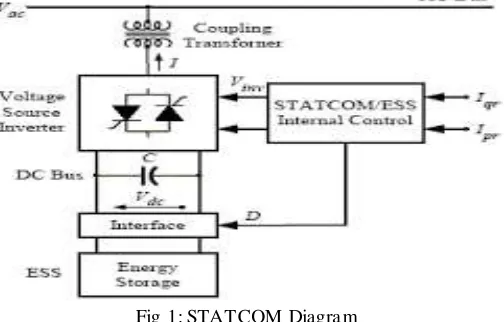
Fig 1: STATCOM Diagra mThe insulated gate bipolar transistor (IGBT) is a three-termina l semiconductor device, for high effectiveness and fast switching. It switches electric power in many modern appliances: electrical ca rs, train and variab le speed drives and refrigerators and air-cooler and even stereo systems with switching a mplifiers. Since it is designed to quickly turn on and off, a mp lifie rs that use it frequently synthesize co mple x waveforms with pulse width modulation and lo w-pass filters.
The IGBT comb ination of the simp le gate-drive characteristics of MOSFET with the high-current and low– saturation-voltage capability of bipolar transistors by combin ing an isolated gate. The IGBT is used in medium- to high-power applications such as switched-mode power supply, traction motor control and induction heating for large IGBT modules typically consist of many devices in parallel and have very high current handling abilities.
Pulse width modulation refe rs to a method of carrying informat ion on train of pulses and the information be enclosed in the width of pulses. The AC voltage is dependent on two parameters i.e . a mp litude and frequency. It is essential to control these two parameters. In th is project single pulse width modulation control technique used. The single pulse width modulation control, the width of the pulse is varied the inverter output voltage and there is only one pulse half per cycle. The advantages of this technique are the power loss in the switching devices is very low.
B. Neural network Controller
Artific ia lneuralnetwork isareplicationofourhumanbra in. The understanding,
recognizing,classifying,clustering,erro rdetectionand correction are the sixth sense of human brain and this
capability is
incorporatedwiththehelpofartific ia lneuralnetwork.
Thisisanemulat ion ofbiological neuralsystem. Neuralnet workcanbesaidtoresemblehu man brain in followingthebelowmentionedthings. Back propagation algorith m is used to inject reactive power in system.The networkarchitectureis mu lti-layer fe e d -forward. Butduring learning process,itisafeedback netwo rk. Delta learn ingruleisusedinthetraining phase.
In thiswork,thelayersusedarethree. Theinputsusedaretheerror andchangeinerrorofthecurrents. Theoutputisthedqvoltages forproperfixing ofthedclinkvoltageofthecapacitorandreactivepower
compensation. Inthehiddenlayer,therearefourneurons.
1.
Algorithm for the design of neural network
controller
Theinputpatternsarepresentedto thenetwork.
Theinputsaresenttothehiddenneurons withastrength
of𝑊𝑖𝑗.For thenetsumtan
sigmoida lactivationfunctionisapplied. Thesignalsfrom
thehiddenunitsaresenttotheoutputlayerwitha strengthof𝑉𝑗𝑘.
Linearactivationfunctionisappliedandthefinaloutputis availableat theoutputneuron.
Theoutputiscompared
withthetargetanderrorgenerated is calculated. ThechangesinthehiddentooutputweightsΔWjk
iscalcu latedand thenthechangesin theinputto hiddenweightsΔ Wijarecalcu lated.
Theweightsareupdatedusingtheformula Wjknew=Wjkold +ΔWjk
Wijnew=Wijold +ΔWij
IJEDR1702132
International Journal of Engineering Development and Research (
www.ijedr.org
)
797
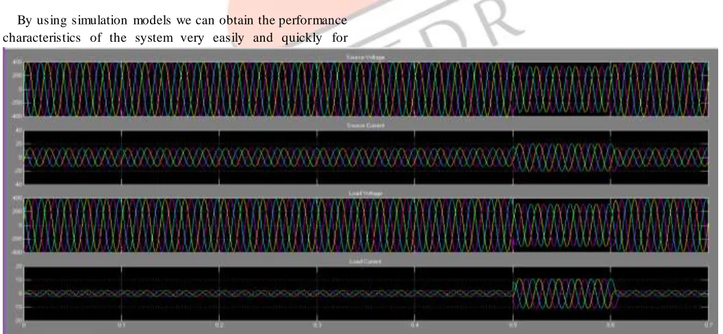
IV.SIM ULATIONANDRESULTANA LYSISBy using simulation models we can obtain the performance characteristics of the system very easily and quickly for
analysis purpose. Here, we consider the performance analysis of UPQC based power quality conditioning device.
A. Analysis
To prevent a voltage sag, STATCOM device useful to inject react ive power [9]. The co mpensation device only active when the system need it, otherwise this unit re ma in absent. The STATCOM g ives reactive power through filter to power source. The main advantages for using filter is to eliminate noise.
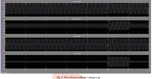
The results of simu lation shown in figure 4 and figure 5 . Figure 4 c learly gives the output waveform of powe r system with voltage sag. The time period of voltage sag is between 0.5 to 0.6 sec. In this time period, power system lags voltage because of some disturbances. Due to disturbances , power system operation affects manyequipment[12].To avoid the damage in equip ment, it is very important to compensate the sag.
The compensation of voltage value done by injecting reactive power to a system to improve power quality. Reactive power in jecting to a system with a help of generating system. In between of compensation system and voltage sag system, filter unit used to avoid disturbance in voltages.
IJEDR1702132
International Journal of Engineering Development and Research (
www.ijedr.org
)
798
Fig 4: Waveform with voltage sagFig 5: Waveform without voltage sag
V.CONCLUSION
In this paper, the effect of voltage sag on the microgridhas been studied and the role of STATCOM on the mitigation of the voltage dip have been found out. The simu lations are carried out in MATLAB and its results are analysed with & without STATCOM connected in the microgrid.The performance of STATCOM is increased by using artific ia l neural network in the present technique. The harmonics is reduced and fault clearing time is increased by using artific ial neural network. Fro m the output shown in mat lab simu lation it has been proved that voltage sag can be reduced using neural network controller co mpared to PI controller.
REFERENCES
[1] P. S. Sensarma, K. R. Padiyar, V. Ramanarayanan “Analysis and Performance Evaluation of a Distribution STATCOM for Compensating Voltage Fluctuations” IEEE TRANSACTIONS ON POWER DELIVERY, VOL. 16, NO. 2, APRIL 2001 [2] RitwikMajumder “Reactive power compensation in single phase
operation of Microgrid” IEEE Transaction on Industrial Electronics, vol.60, No.4, April.2013
[3] Surinder Chauhan, Vikram Chopra, Shakti Singh “Transient Stability Improvement of Two M achine System using Fuzzy Controlled STATCOM” International Journal of Innovative Technology and Explorin g Engineering (IJITEE) , Volume-2, Issue-4, M arch 2013
[4] Wei Qiao, Ronald G. Harley, Ganesh Kumar Venayagamoorthy “Coordinated Reactive Power Control of a Large Wind Farm and a STATCOM Using Heuristic Dynamic Programming” IEEE TRANSACTIONS ON ENERGY CONVERSION, VOL. 24, NO. 2, JUNE 2009
[5] Aman Ganesh, RatnaDahiya and G. K. Singh “A novel STATCOM wide area feedback controller for improving stability in multimachine system” International Conference on Power Systems, Energy, Environment, 2014
[6] Ganesh P. Prajapat, Prof. S. Chhatterji, M rs. Lini M athew “Performance Analysis of 48-Pulse VSC-Based STATCOM in M itigation of Voltage Dip Caused by The Starting of A High Power Induction-M otor” International Journal Of Engineering Research And Development Volume 4, Issue 6 (October 2012), PP. 01-05
[7] Md. Nazrul Islam, Md. ArifurKabir, Yashiro Kazushige “Design and Simulation of STATCOM to Improve Power Quality” International Journal of Innovation and Applied Studies ISSN 2028-9324 Vol. 3 No. 3 July 2013, pp. 871-878
IJEDR1702132
International Journal of Engineering Development and Research (
www.ijedr.org
)
799
COMPENSATION OF EHV TRANSMISSION LINE”International Journal of Advanced Research in Electrical, Electronics and Instrumentation Engineering, Vol. 2, Issue 7, July 2013
[9] Mukesh M. Bhesaniya, Anshuman Shukla “Current Source M odular M ultilevel Converter: Detailed Analysis and STATCOM Application” IEEE Transactions on Power Delivery, VOL.31, NO.1, FEBRUARY 2016
[10]Pranesh Rao, M. L. Crow, Zhiping Yang “STATCOM Control for Power System Voltage Control Applications”IEEE Transaction on power delivery, vol.15, No.4, OCTOBER 2000.
[11]] Priyanka Sahu, Govind Prasad Pandiya “Implementation of Power Quality Improvement & Reactive Power Compensation Using Fact Device STATCOM Using Hydro System” International Journal Of Innovation In Engineering Research & M anagement, VOLUM E :04,February 2017
[12]Prof. Ashish Choubey, Gunshekhar Singh “Steady State Voltage Stability Improvement by Determination of best Location of STATCOM with M inimum Losses” Volume 2, Issue 4, 2016 [13] S. Deepa, S. Praba “A Fuzzy GA Based STATCOM for Power
Quality Improvement” International Journal of Power Electronics and Drive System (IJPEDS) Vol. 8, No. 1, M arch 2017, pp. 483~491
[14]Sumeet Trivedi, D. Chattopadhyay “Voltage Sag Mitigation in the Distributed Generation System with STATCOM” International Journal of Emerging Technology and Advanced Engineering, Volume 3, Issue 10, October 2013