© 2017 IJSRST | Volume 3 | Issue 7 | Print ISSN: 2395-6011 | Online ISSN: 2395-602X Themed Section: Science and Technology
Earthquake Analysis of High rise Building Using Birdcage
Interlocking Frame with Combination of Shear Walls
E. Murali Goud
1, A.B.S. Dadapeer
2*1M.Tech Student, St.Mark Educational Institutions Society Group of Institutions, Anantapur, Andhra Pradesh, India 2Assistant Professor, Department of Civil Engineering, St.Mark Educational Institutions Society Group of Institutions, Anantapur,
AndhraPradesh, India
ABSTRACT
Earthquakes are among the most deadly natural hazards. There are around 100 earthquakes each year of a size that could cause serious damage. Earthquakes strike without warning and many of the Earth‟s earthquake zones coincide with areas of high population density. When large earthquakes occur in such areas the results can be catastrophic, with terrible loss of human lives and untold economic cost. To overcome due to seismic and wind loads, providing birdcage like structure around the building which consists of steel sections (like I-sec, C-sec, & etc.) It protects the building by providing cage around the structure at elevation which prevents the structure from deflection or displacement of building due to wind and seismic loads. Some buildings have supporting steel frames that interlock called Birdcages. Steel is more flexible that brick and concrete. This allows the frames to bend, rather than break, under the force of an earthquake. The basic principles of design for vertical and lateral loads (wind & seismic) are the same for low, medium or high rise building. But a building gets high both vertical & lateral loads become controlling factors. The vertical loads increase in direct proportion to the floor area and number of floors. In contrast to this, the effect of lateral loads on a building is not linear and increase rapidly with increase in height. Due to these lateral loads, moments on steel components will be very high. One of the most important aspects is to construct a building structure, which can resist the seismic force efficiently. Study is made on the different structural arrangement to find out the most optimized solution to produce an efficient safe earthquake resistant building. The extent of the damage depends on the strength of the vibrations or the energy associated with them. It also depends on the density of population and the way buildings are constructed. An Educational package ETABS has been utilized for analysing high-rise building of 66.5m height and for different zones. The results of the analysis on the shear force, bending moment and Torsion are compared. The results are presented in tabular and graphical form.
Keywords: Earthquake, Hazard, Birdcage, Interlocking Frame, Deflection, Shear Force, Bending Moment
I.
INTRODUCTION
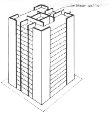
SHEAR WALL STRUCTURES
Adequate stiffness is to be ensured in high rise buildings for resistance to lateral loads induced by wind or seismic events. Reinforced concrete shear walls are designed for buildings located in seismic areas, because of their high bearing capacity, high ductility and rigidity. In high rise buildings, beam and column sizes work out large and reinforcement at the beam-column junctions are quite heavy, so that, there is a lot of clogging at these joints and it is difficult to place and vibrate concrete at these places which does not contribute to the safety of
responsible for the lateral load resistance of the building due to seismic and wind loadings. These shear walls act as vertical cantilevers in the form of separate planar walls, and also as non-planar assemblies of connected walls around stair case, elevators and service shafts. Shear walls are much stiffer horizontally than rigid frames. Shear walls are much economical up to about 35 stories. In contrast to the rigid frames, the shear walls‟ solid form tends to restrict open internal spaces where required. However, they are well suited to hotels and residential buildings where the floor by floor repetitive planning allows the shear walls to be vertically continuous. They also serve excellent acoustic and fire insulators between rooms and apartments.
II.
STRUCTURAL FORMS
Lateral loads can develop high stresses, produce sway movement or cause vibration. Therefore, it is very important to have sufficient strength for the structure against vertical loads. Earthquake and wind forces are the only major lateral forces that affect the buildings. The function of lateral load resisting systems or structure form is to absorb the energy induced by these lateral forces by moving or deforming without collapse. The determination of structural form of a tall building or high rise building would perfectly involve only the arrangement of the major structural elements to resist most efficiently the various combinations of lateral loads and gravity loads. The structural considerations strongly influence the selection of structural form. The ability of the structural system and material to deform and absorb energy without collapse or fracture is termed as ductility. All these structural forms resist force in three basic ways: bending or flexure, shear and axial tension or compression.
Figure 1. Structural system categories
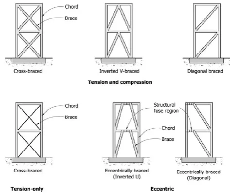
III. BRACED-FRAME STRUCTURES
In braced frame structures the diagonal members act together with the girders to form the „web‟ of the vertical truss, with the columns acting as the „chords‟. The horizontal shear on the building is resisted by the horizontal components by means of axial tensile or compressive actions in the web members. In resisting lateral loads bracing systems are highly efficient. Bracing is usually regarded as an exclusively steel system since the diagonals are mainly subjected to tension in one or the other directions of lateral loading. Concrete bracings of double diagonal form are also used with each diagonal designed as a compression member to cart the full external shear.
Figure 2. Various types of bracings
IV. RIGID FRAME STRUCTURES
Figure 3. Rigid frame: Forces and Deformations
IN-FILLED FRAME STRUCTURES:
In filled frame structures are the most common form of construction for high rise buildings up to 30 stories in height. Column and girder framing of reinforced concrete is infilled by panels of brickwork, block work or cast-in-place concrete. The infill behaves effectively as a strut along its compression diagonal to brace the frame when the infilled frame is subjected to lateral loading.
Figure 4. Infilled Frame
FLAT-PLATE AND FLAT-SLAB STRUCTURES:
The simplest structural framing techniques for a concrete building consist of a two way floor slab framing directly into columns without beams. The system, which is essentially of reinforced concrete, is
very economical in having a flat soffit requiring the most uncomplicated formwork.
Figure 5. Flat-plate and Flat-slab structures
SHEAR WALL STRUCTURES:
Reinforced concrete walls are classified according as bearing walls, non-bearing walls, shear walls, flexural shear walls, and squat shear walls. Shear walls are a part of the lateral force resisting system that carries vertical loads, bending moments about the wall strong axis, and shear forces parallel to the wall length. Shear wall system is one of the most common and effective lateral load resisting systems that are widely used in medium to high-rise buildings.
V.
THE ROLE OF FLOOR DIAPHRAGMS IN
FRAMED BUILDINGS:
The role of floor diaphragm is important in the case of framed buildings. The floor diaphragm forces all the vertical elements like frames, walls and shear walls to share the incumbent horizontal shear in the ratio of their stiffness or rigidities. The function of a floor or roof, acting as a diaphragm, is to transmit inertia forces generated by earthquake accelerations of the floor mass at a given level to all lateral resisting elements. At certain stories, as a response to architectural requirements, particularly in lower stories, significant horizontal forces from frame or shear wall, may need to be transferred to walls, usually stiffer element. These actions generate significant shear forces and bending moments within a diaphragm in long or articulated floor plans.
Figure 5. Diaphragm with opening
BIRD CAGE INTERLOCKING FRAME :
It is Steel Frame which is provided around the Framed Structure To resist the structure from lateral loads, Earth Quake Loads & Wind load .A Steel Section of I, Channel Sections are used for the interlocking System. It Interlocks the Building against the lateral forces so it is named as Bird Cage Interlocking Frame.
ARCHITECTURAL FEATURES:
In order to create an aesthetic and functionally efficient structure drives architects to visualize wonderful and imaginative structures. Sometimes the shape of the building makes the visitor to have a glance at it, sometimes the structural system of work together to make the structure a wonder. So, the choices of shapes and structure has significant bearing on the performance of the structure during past earthquakes across the world is very educative in identifying structural configurations which are desirable and which must be avoided.
DYNAMICS OF SOILS AND SEISMIC RESPONSE:
Soil dynamic problems are generally divided into either small strain amplitude or large strain amplitude responses. Under the influence earthquake loading the soil element may be in any one of the following conditions.
1. The initial static stress is large and the additional stresses induced by the earthquake are small.
2. The sustained stress is small and the pulsating strain is larger.
an embankment, the soil elements withstand shear stresses in either direction. Soil behaviour under dynamic loading depends on the strain magnitude, the strain rate and the number of loading cycles. The strength certain soils increases under rapid cyclic loading, while saturated or sensitive clay may lose strength with vibration. In the case of lose sands, it appears that sand with relative density below 60% or saturated penetration resistance below 15 is susceptible to significant settlement. Gravel or clay is not susceptible to liquefaction, and dense soils are less likely to liquefy than loose sand, while hydraulically deposited sands are particularly vulnerable due to their uniformity.
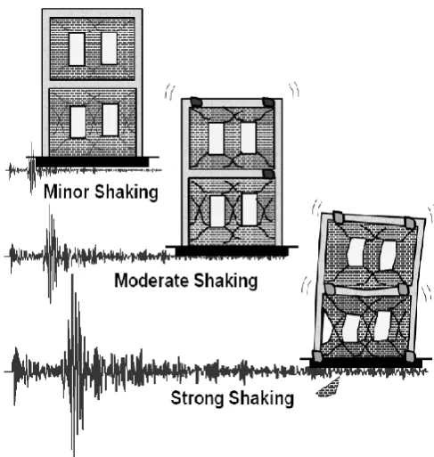
As, the actual forces will be much larger than the design forces specified by the code, the ductility arising from the inelastic material behaviour and detailing along with the reserve strength are relied upon to account for the difference in the actual and the design lateral loads. Conceptual representation of earthquake resistant design philosophy is depicted in the following figure;
Figure 6. Schematic diagram depicting earthquake resistant design philosophy for different levels shaking.
VI. RESPONSE SPECTRUM ANALYSIS
This method is also known as modal method or mode superposition method. It is based on the idea that the response of a building is the superposition of the
responses of individual modes of vibration, each mode responding with its own particular deformed shape, its own frequency, and with its own modal damping. According to IS-1893(Part-l):2002, high rise and irregular buildings must be analysed by response spectrum method using design spectra shown in Figure 4.1. There are significant computational advantages using response spectra method of seismic analysis for prediction of displacements and member forces in structural systems. The method involves only the calculation of the maximum values of the displacements and member forces in each mode using smooth spectra that are the average of several earthquake motions. Sufficient modes to capture such that at least 90% of the participating mass of the building (in each of two orthogonal principle horizontal directions) have to be considered for the analysis. The analysis is performed to determine the base shear for each mode using given building characteristics and ground motion spectra.
STEP BY STEP PROCEDURE FOR EQUIVALENT STATIC FORCE ANALYSIS:
Step-1: Depending on the location of the building site, identify the seismic zone and assign Zone factor (Z). Use Table 2 along with Seismic zones map or Annex of IS-1893 (2002)
Step-2: Compute the seismic weight of the building (W); • As per Clause 7.4.2, IS-1893 (2002) – Seismic weight of floors
• As per Clause 7.4.3, IS-1893 (2002) – Seismic weight of the building
Step-3: Compute the natural period of the building (Ta) • As per Clause 7.6.1 or Clause 7.6.2, IS-1893 (2002), as the case may be.
Step-4: Obtain the data pertaining to type of soil conditions of foundation of the building
• Assign type, I for hard soil, II for medium soil & III for soft soil
Step-5: Using Ta and soil type (I / II / III), compute the average spectral acceleration (Sa/g)
• Use Figure 2 or corresponding table of IS-1893 (2002), to compute (Sa/g).
Step-6: Assign the value of importance factor (I) depending on occupancy and/or functionality of structure
• As per Clause 7.2 and Table 7 of IS-1893 (2002) Step-8: Knowing Z, Sa/g, R and I compute design horizontal acceleration coefficient (Ah) using the relationship,
Step-9: Using Ah and W compute design seismic base shear (VB), from B h V = AW [Clause 7.5.3, IS-1893 (2002)]
Step-10: Compute design lateral force (Qi) of ith floor by distributing the design seismic base shear (VB) as per the expression,
PLANS AND LAYOUTS OF MODELS: MODEL-1
Figure 7. Showing Plan, Elevation & 3D Model Without BC & SW MODEL-2
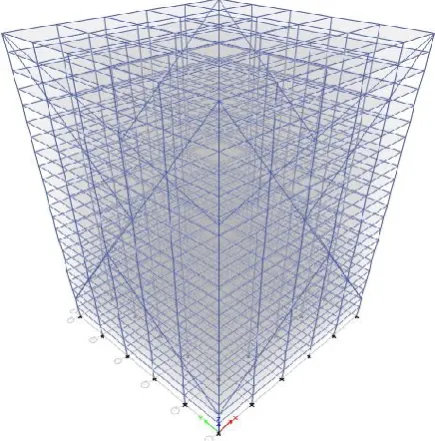
Figure 8. Showing Plan, Elevation & 3D Model With BC MODEL-3
VII.
RESULTS
Results from the equivalent static method:
The following tables and graphs are obtained from ETABS and analysis is done by using Equivalent static method. For each shape of shear wall the optimum model is selected and the values of those models are only compared with the model without shear wall.
Storey Displacement:
The total lateral displacement that occurs in a single story of a multistory building is termed as story displacement. It is a simple parameter that offers an estimation of the lateral stiffness of a building in the form of displacement index and it is defined as the ratio of the maximum deflection at the top of the structure to the total height of the structure. In addition the corresponding value of the single storey height, the inter storey height, the inter storey displacement gives a measure of possible localized excessive deformation. The control of the lateral deflection has particular importance for modem structures, in which traditional reserves of stiffness due to heavy internal partitions and outer cladding have largely vanished.
Graph: Showing Displacement Variation in Z-2 S-1
Graph: Showing displacement variation in Z-2 S-2
VIII.
CONCLUSIONS
From analytical results, it is observed that base isolation technique is very significant in order to reduce the seismic response of both symmetric as well as asymmetric models as compared to fixed base building and control the damages in building during strong ground shaking. By comparing the dynamic properties of buildings following conclusions are made:
1. It has been observed that maximum Storey displacement was decreased of about 40% by providing Bird Cage Interlocking Frame, the displacement gradually decreases for top storey of base isolated building as compared with fixed base building model.
2. It has been observed that maximum Storey Shears and Base Shear was decreased of about 50% by providing Bird Cage Interlocking Frame, the Shear gradually decreases for top to bottom storey of base isolated building as compared with fixed base building model.
3. It has been observed that maximum Moment and Base Moment was decreased of about 50% by providing Bird Cage Interlocking Frame, the Moment gradually decreases for top to bottom storey of base isolated building as compared with fixed base building model.
4. From analytical study, it is observed that for both models of symmetric as well as asymmetric, fixed
d
isp
lac
e
No of stories
Z-2 S-1 IN X DIRECTION
STORIES VS DISP
without bc
with bc
with sw + bc
d
isp
lac
e
m
e
n
t
stories z-2,s-2displacement
disp. vs stories
without
with bc
base building have zero displacement at base of building whereas, base isolated building models shows appreciable amount of lateral displacements at base. Also it has been observed that as floor height increases, lateral displacements increases drastically in fixed base building as compare to base isolated building. Due to this reduction in lateral displacement during earthquake damages of structural as well as non-structural is minimized. 5. It is observed that for fixed base building have zero
storey acceleration at base of building whereas, in case of base isolated building model appreciable amount of storey acceleration has been found out at base. Also it has been observed that as floor height increases, storey acceleration increases drastically in fixed base building as compared to base isolated building where it is almost constant.
6. It is observed that for fixed base building have zero storey acceleration at base of building whereas, in case of base isolated building model appreciable amount of storey acceleration has been found out at base. Also it has been observed that as floor height increases, storey acceleration increases drastically in fixed base building as compared to base isolated building where it is almost constant.
7. From the study of symmetric building models it can be concluded that Shear force, Bending moment, Storey Displacement symmetric building model. Therefore it is concluded that symmetrical building with base isolation remains strong enough during earthquake.
IX. CONCLUSION
The proposed payment system combines the Iris recognition with the visual cryptography by which customer data privacy can be obtained and prevents theft through phishing attack [8]. This method provides best for legitimate user identification. This method can also be implemented in computers using external iris recognition devices.
X.
REFERENCES
[1]. IS: 456-code of practice for plain and reinforced concrete
[2]. IS: 875(part 1-5) - code of practice for structural safety of Building loading standards
[3]. IS 1893(Part-1):2002, Criteria for earthquake resistant design of structures.
[4]. IS 13920:1993, Ductile detailing of reinforced concrete structure subjected to seismic forces- code of practice.
[5]. SP: 16-design aids for reinforced concrete [6]. Earthquake resistant design by pankaj agarwal. [7]. Rosinblueth and Holtz “Analysis of shear walls in
tall buildings” (1960)
[8]. Clough.R, King I.P and Wilson E.I-“Structural analysis of multi storied buildings” (1964)
[9]. Khan, F.R. and Sbrounis, J.A, (7) „Introduction of shear wall with frames in concrete Sabrcounis structure under lateral loads (1964).