An Approach for Modelling Architectural Design
Rules in UML and its Application to Embedded
Software
9
A. MATTSSON
Combitech AB, Sweden
B. FITZGERALD
Lero – the Irish Software Engineering Research Centre, University
of Limerick, Ireland
B. LUNDELL AND B. LINGS
University of Skövde, Sweden
________________________________________________________________________
Current techniques for modelling software architecture do not provide sufficient support for modelling of architectural design rules. This is a problem in the context of Model-Driven Development in which it is assumed that major design artefacts are represented as formal or semi-formal models. This paper addresses this problem by presenting an approach to modelling architectural design rules in UML at the abstraction level of the meaning of the rules. The high abstraction level and the use of UML makes the rules both amenable to automation and easy to understand for both architects and developers, which is crucial to deployment in an organization. To provide a proof-of-concept a tool was developed that validates a system model against the architectural rules in a separate UML model. To demonstrate the feasibility of the approach the architectural design rules of an existing live industrial strength system were modelled according to the approach.
Categories and Subject Descriptors: D.2.11 [Software Engineering]: Software Architectures – Languages D.2.2 [Software Engineering]: Design tools and techniques – Computer-aided software engineering (CASE);Object-oriented design methods; D.2.1 [Software Engineering}: Requirements/Specifications – Methodologies; Tools General Terms: Design, Documentation, Human Factors
Additional Key Words and Phrases: Model-Driven Development (MDD), Model-Driven Engineering (MDE), Embedded Software Development
ACM Reference Format:
<to be included>
________________________________________________________________________
1. INTRODUCTION
A basic premise of Model-Driven Development (MDD) [Schmidt 2006] is to capture all important design information in a set of formal or semi-formal models that are automatically kept consistent by tools. The purpose is to raise the level of abstraction at which the developers work and to eliminate time consuming and error-prone manual work in maintaining consistency between different design artefacts such as UML diagrams and code. An important design artefact in any software development project is the software architecture [Bass et al. 2003]. The purpose of the architecture is to guide
This research has been financially supported by the ITEA project MoSiS (www.itea-mosis.org) through Vinnova (www.vinnova.se) and also by funding from Science Foundation Ireland to Lero (www.sfi.ie). Authors’ addresses: A. Mattsson, Combitech AB, P.O. Box 1017, SE-551 11 Jönköping, Sweden. E-mail: [email protected]; B. Fitzgerald, Lero – the Irish Software Engineering Research Centre, University of Limerick, Ireland. E-mail: [email protected]; B. Lundell and B. Lings, University of Skövde, P.O. Box 408, SE-541 28 Skövde, Sweden. E-mail: {bjorn.lundell, brian.lings}@his.se.
and control the design of the system so that it meets its quality requirements. A common way of capturing the architecture in MDD projects is to put the high level structure in the form of packages and components with interfaces in the system model, together with a framework implementing a communication infrastructure used by the components [Mattsson et al. 2009]. This is however not enough; you also need to specify rules as to what kinds of component to put in different layers and how these are supposed to use the infrastructure. We call these rules architectural design rules [Mattsson et al. 2009]. The current state of practice is to express these rules in informal text for the developers to follow. This means that manual reviews have to be used to check that the rules have been followed during detailed design. If we could model architectural design rules in a form that could be interpreted by tools, and at the same time easily be understood by both architects and developers, we would be able to eliminate error prone and time consuming manual work.
In this paper we present an approach to solving this problem by using the well-known modelling language UML [OMG 2009] to define architectural design rules at the meta-model level in an intuitive way. To verify that the approach can be automated, a tool has been built that checks that a system model conforms to architectural design rules modelled according to the approach. To demonstrate the applicability of the approach to real systems development the architectural design rules of an already developed real-world embedded system has been modelled according to the approach.
The rest of this paper is organized as follows. In the next section we present the background motivating the research. In section three we introduce a fictional but realistic example to illustrate the problem of modelling architectural design rules and to introduce our proposed solution. Thereafter we present the research approach adopted for the study. Following this, our findings are presented in three consecutive sections covering the definition of the approach, tool support for automation, and the results from applying the approach to a real-world system. Finally we discuss our conclusions and the implications of the findings.
2. BACKGROUND
Our main research objective was to define an approach for modelling architectural design rules in an intuitive way while also stringent enough for automation. In order to motivate and validate our research objective we conducted a literature review in line with [Levy and Ellis 2006]. The review consisted of two consecutive phases where the first phase focused on the role of architectural design rules in the context of MDD. The findings from this phase are presented in section 2.1. Since we have reported these findings in [Mattsson et al. 2009], where a detailed discussion can be found, this part is kept brief in this paper. Informed by the findings of the first phase the second phase of the literature review focused on techniques for using UML to constrain UML modelling. The findings from this phase are presented in section 2.2.
2.1 Architectural design rules and MDD
The purpose of the architecture is to guide and control the design of the system so that it meets its quality requirements. Bass et al. [Bass et al. 2003] are unequivocal in stating the importance of an architectural approach:
“The architecture serves as the blueprint for both the system and the project developing it. It defines the work assignments that must be carried out by design and implementation teams and it is the primary carrier of system qualities such as performance, modifiability, and security – none of which can be achieved without a unifying architectural vision. Architecture is an artefact for early analysis to make sure that the design approach will yield an acceptable system. Moreover, architecture holds the key to post-deployment system understanding, maintenance, and mining efforts. In short, architecture is the conceptual glue that holds every phase of the project together for all of its many stakeholders.”
A common understanding in architectural methods is that the architecture is represented as a set of components related to each other [Perry and Wolf 1992; Shaw et al. 1995]. The components can be organized into different views focusing on different aspects of the system. Different methods propose different views; there may be a view showing the development structure (e.g. packages and classes), a view showing the runtime structure (processes and objects) and a view showing the resource usage (processors and devices). In any view each component is specified with the following:
− an interface that documents how the component interacts with its environment.
− constraints and rules that have to be fulfilled in the design of the component.
− allocated functionality.
− allocated requirements for quality attributes.
A typical method of decomposition (see for instance [Bass et al. 2003], [Wojcik et al. 2006] and [Bosch 2000]) is to select and combine a number of patterns that address the quality requirements of the system and use them to divide the functionality in the system into a number of elements. Child elements are recursively decomposed in the same way down to a level where no more decomposition is needed, as judged by the architect. The elements are then handed over to the designers who detail them to a level where they can be implemented. For common architectural patterns such as Model-View-Controller, Blackboard or Layers [Buschmann 1996] this typically means that you decompose your system into subsystems containing different kinds of classes (such as models, views and controllers). However the instantiation into actual classes is often left to the detailed design, for two main reasons:
1. Functionality will be added later, either because it was missed or because a new
version of the system is developed, so more elements will be added later that also have to follow the design patterns decided by the architect.
2. It is not of architectural concern. The concern of the architect is that the design
follows the selected architectural patterns, not to do the detailed design.
This means that a substantial part of the architecture consists of design rules as to what kinds of elements, including behavioural and structural rules and constraints, should be in a certain subsystem.
The importance of architectural design rules is also highlighted in current research in software architecture which is focused on the treatment of architectural design decisions as first class entities [Jansen and Bosch 2005; Jansen et al. 2007; Kruchten 2004; Kruchten et al. 2006; Tyree and Akerman 2005], where architectural design decisions impose rules and constraints on the design together with a rationale. However, there is
not yet any suggestion on how to formally model these design rules. The current suggestion is to capture them in text and to link them to the resulting design. This may be sufficient for rules stating the existence of elements (“ontocrisis” in [Kruchten 2004]) in the design, such as a subsystem or an interface, since the architect can put the actual element (i.e. a certain subsystem) into the system model at the time of the decision. It is however not sufficient for rules on potentially existing elements (“diacrisis” in [Kruchten 2004]) such as rules as to what kinds of elements, including behavioural and structural rules and constraints, should be in a certain subsystem, since the actual elements are not known when the design decision is made. Instead, the rule-based design occurs later in the detailed design phase, and involves other persons, potentially even in a different version of the system.
As previously reported [Mattsson et al. 2009] there is no satisfactory solution to how to model architectural design rules on potentially existing components in the current body of literature:
− Approaches to MDD, such as OMG’s MDA [OMG 2003], Domain Specific
Modelling (DSM) [Karsai et al. 2003; Tolvanen and Kelly 2005], and Software Factories [Greenfield and Short 2004] from Microsoft do not address the problem of how to represent architectural design rules.
− Numerous methods exist for architectural design such as ADD[Bass et al. 2003;
Wojcik et al. 2006], RUP 4+1 Views [Kruchten 2004; Kruchten 1995], QASAR [Bengtsson and Bosch 1998; Bosch 2000; Bosch and Molin 1999], S4V [Hofmeister et al. 2000; Soni et al. 1995], BAPO/CAFCR [America et al. 2004; van der Linden et al. 2004] and ASC [Ran 2000]. Also, current research in software architecture is focused on treating architectural design decisions as first class entities [Jansen and Bosch 2005; Jansen et al. 2007; Kruchten 2004; Kruchten et al. 2006; Tyree and Akerman 2005]. However neither of these research streams provides any suggestion as to how architectural design rules should be modelled, other than as informal text.
− Architectural Description Languages (ADL) [Medvidovic et al. 2007;
Medvidovic et al. 2002; Medvidovic and Taylor 2000] (e.g. ACME, Aesop, C2, MeatH, AADL, SysML and UML) do not provide sufficient means to specify constraints or rules on groups of conceptual components only partly specified by the architect where the actual components are intended to be indentified and designed by developers in later design phases.
The state of the art in embedded software development [Mattsson et al. 2009] is to capture these rules in a text document. This means that we have to rely on manual reviews to ensure that the detailed design follows the architectural design rules. As a consequence, architectural enforcement becomes a bottleneck in MDD, where other design activities have been automated. As earlier reported [Mattsson et al. 2009] this leads to a plethora of problems, including:
1. Stalled detailed design: The design teams have to wait for the architects to
review their overall design before they can dig deeper into the design.
2. Premature detailed design: Design teams commence detailed design before
their overall design is approved by the architect, with the risk that they will have to redo much work after the review.
3. Low review quality: Time pressures lead to a low quality of review, leading to problems later in the project.
4. Poor communication of architecture: The architects have no time to handle
the communication with the design teams regarding architectural interpretations or problems; problems are “swept under the carpet.”
An architectural style (also known as architectural pattern) [Shaw and Garlan 1996] is an idiomatic pattern of system organization. It is comparable to the solution part of a certain kind of design pattern [Gamma 1995] specifying system wide design rules, categorized as architectural patterns in [Buschmann 1996].
The problem of modelling design rules has much in common with the problem of modelling architectural styles or the solution part of a design pattern in so far as it basically is about specifying rules to follow in the design. There are a number of suggestions on how to formally model design pattern specifications and architectural styles [Bayley 2007; Eden 2002; France et al. 2004; Lauder and Kent 1998; Mak et al. 2004; Mikkonen 1998; Pahl et al. 2007; Zdun and Avgeriou 2005]. While some approaches use mathematical formalisms such as predicate logic and set theory, others use UML applied at the meta-model level. Based on our experience we believe that, in order to be successful in practice, it is essential that architectural design rules are modelled in such a way that they are both amenable to automatic enforcement of the detailed design and easy to understand and use by both architects and developers. The latter is important in order to avoid increasing the work of developing the rules; otherwise there is a risk that the work burden is increased instead of decreased even though the enforcement is automated. Another important issue is that it should be possible to use current mainstream modelling tools to model both the architectural design rules and the system model so as to make it widely adoptable. Given that UML is probably the most widely used modelling language in the embedded software industry our choice would therefore be to use UML to model architectural design rules for UML models. Our approach is therefore based on the same idea as in [Zdun and Avgeriou 2005] and [France et al. 2004], namely to use UML on the meta-model level to restrict the use of UML in a system model. However, instead of using it to specify patterns, we use it to specify architectural design rules.
2.2 Architectural design rules in an MDD context using UML
The purpose of architectural design rules is to provide the necessary constraints for the detailed design. In an MDD context where the detailed design is made in UML this means that the architectural design rules must be modelled in such a way that they restrict how UML is used. Furthermore, to suit our purpose, it must be possible to automatically enforce the restrictions on the detailed design or to automatically check that the restrictions are followed in the detailed design. Within UML, a profile provides a mechanism to restrict the use of UML [Fuentes-Fernández and Vallecillo-Moreno 2004]. A UML profile contains a number of stereotypes where each stereotype extends one or more UML meta-classes with new properties and constraints. The stereotype can then be applied to model elements of the extended meta-class in a model using the profile. In Fig. 1 an example is given where we define a stereotype Data_Class that extends the UML meta-class Class. The stereotype adds the constraint that Classes with the stereotype Data_Class cannot have any operations. The constraint is expressed in OCL [OMG 2003], a language for specifying constraints and queries on models in UML and other
MOF [OMG 2006] based languages defined by OMG (MOF is a subset of UML intended for meta-modelling). The application of this stereotype is shown in Fig. 2 where we define a class Position with the stereotype Data_Class.
<<stereotype>> Data_Class <<metaclass>>
Class
{self.base_Class.ownedOperation->size()=0}
Fig. 1 Defining a stereotype Data_Class in a UML profile
<<Data_Class>> Position + Longitude : int + Lattitude : int
Fig. 2 Defining a class Position of the stereotype Data_Class in a UML model
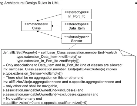
There are, however, at least two problems with defining profiles in this way. The first problem is that it requires detailed knowledge of the UML meta-model (the model defining the abstract syntax of UML), which is quite complex and beyond what can be expected from a typical architect or developer; it would be likely to impede widespread adoption of the approach [Conboy and Fitzgerald 2010]. For example, the very simple constraint in Fig. 1 requires the knowledge that operation has the role name ownedOperation in its association to Class in the UML meta-model. The second problem is that the OCL expressions become quite complex even for quite simple constraints. Consider the following example rule (rule S4 in the illustrating example in section 3):
A sensor may only have associations to In_Port_Ifc and Data_Items. These associations shall only be navigable from the sensor.
Using the standard approach for defining profiles we get the constraint definition for the Simulator stereotype shown in Fig. 3. As can be seen, this involves a great deal of detailed knowledge of the UML meta-model.
<<metaclass>>
Class <<stereotype>>Data_Item <<stereotype>>
Sensor
def: allE:Set(Property) = self.base_Class.association.memberEnd->select( type.extension_Data_Item->notEmpty() or
type.extension_In_Port_Ifc->notEmpty())
-- Only associations to Data_Item and In_Port_Ifc kind of classes are allowed: inv: self.base_Class.association.member_End(e|allE->excludes(e) implies e.type.extension_Sensor->notEmpty())
-- There shall be no aggregation on this or other end
inv: allE->forAll(e|e.aggregation=none and e.opposite.aggregation=none and -- only other end shall be navigable,
e.association.navigableOwnedEnd->includes(e) and e.association.navigableOwnedEnd->excludes(e.opposite) and -- No qualifier on any end
e.qualifier->size()=0 and e.opposite.qualifier->size()=0) <<stereotype>>
In_Port_Ifc
Fig. 3 Definition of the architectural design rule example using OCL
Another possibility is to make a new meta-model with classes that extend the classes in the UML meta-model through generalizations. But, as illustrated in Fig. 4, this is very similar to the approach using a profile, in that one still needs to specify almost the same OCL constraints as when using a profile. The only benefit is that you avoid the navigation between the stereotypes and the elements in the meta-model (e.g. self.base_Class and type.extension_Data_Type)
Data_Item
Sensor Class
UML
def: allE:Set(Property) = self.association.memberEnd->
select(type.oclIsTypeOf(Data_Item) or type.oclIsTypeOf(In_Port_Ifc)) -- Only associations to Data_Item and In_Port_Ifc kind of classes are allowed: inv: self.association.member_End(e|allE->excludes(e) implies
e.type.oclIsTypeOf(Sensor)
-- There shall be no aggregation on this or other end
inv: allE->forAll(e|e.aggregation=none and e.opposite.aggregation=none and -- only other end shall be navigable,
e.association.navigableOwnedEnd->includes(e) and
e.association.navigableOwnedEnd->excludes(e.opposite) and -- No qualifier on any end
e.qualifier->size()=0 and e.opposite.qualifier->size()=0) In_Port_Ifc
Fig. 4 Definition of the architectural design rule example using specialisation of the UML meta-model
What is needed is a technique to specify the constraints in a more intuitive way. In [Fuentes-Fernández and Vallecillo-Moreno 2004] a technique using a meta-model as a precursor to a UML profile specification is suggested. According to this approach stereotypes are defined by classes in a meta-model where the relations between the classes impose constraints on the stereotypes. Using an approach like this the above example would be expressed according to Fig. 5.
Data_Item * Sensor * In_Port_Ifc
Fig. 5 Capturing the architectural design rule example using the approach suggested in [Fuentes-Fernández and Vallecillo-Moreno 2004]
This approach has the benefit that it is more intuitive, it is both easier to model and to understand. Another benefit is that it does not contain any details from the UML meta-model so it does not require any knowledge of that. The drawback of this approach is that it lacks rigour on how to transform it to a UML profile. In the context addressed in [Fuentes-Fernández and Vallecillo-Moreno 2004] this is not a problem since the purpose of the model is just to aid in the process of designing a profile, not to be automatically transformed into a profile. For our purpose a detailed specification as to how it may be transformed to a UML profile is necessary, to the level where it could be implemented in a tool. To that purpose we have defined a set of transformation rules. These are described in section 5.
3. AN ILLUSTRATIVE EXAMPLE
In this section we introduce a fictional but realistic example to illustrate the problem of modelling architectural design rules and to introduce our proposed solution to that problem.
Our fictional system is a product line of washing machines. The product line consists of a wide variety of washing machines from simple cheap machines with a minimum of features to advanced machines with user access control that are monitored and controlled over the internet for industry and public self-service laundries. Since there is a high degree of functional commonality between different machines it has been decided to build a common model from which software for all machines (existing and future) can be generated. With this goal there are a number of non-functional requirements that must be addressed by the architectural design, such as:
1. Performance scalability: In simple machines it shall be possible to run the
software in a microcontroller with very limited performance and memory while the more advanced machines have fully featured CPU’s with hundreds of megabytes of memory.
2. IO hardware variability: Since the availability and price of IO hardware varies
over time change of IO hardware shall require minimal effort.
3. Communication protocols variability: Since different machines use different
protocols for communication with external systems now and in the future, change of communication protocols shall require minimal effort.
4. Functional scalability: Since the functionality is highly variable adding,
removing and changing functionality, including beyond what is considered currently, shall require minimal effort.
5. User interface variability: There is high variability in how the user controls the
machines, from simple variants with knobs and LED´s to touch screens for the most advanced machines. Therefore, it shall require minimal effort to change the interface to the user, including beyond the controls existing currently.
6. Sensor and actuator variability: While some machines use actual sensors to
monitor water temperature and water level others use time to estimate these values. There are also different scalings between the sensor output and measured values for different physical sensors and different machines (e.g. for water level). Depending on the functionality of the machine there are also different kinds of sensor and actuator for different machines (e.g. if the machine also has tumble drying functionality or dirt sensing capabilities). To cater for this variability adding removing or changing sensors and actuators shall require minimal effort.
To handle these requirements the following design principles have been decided by the architect:
1. Performance scalability: No heavy-weight functionality is required. For
example, it might have been sensible to use a database with remote accessibility to store the data items since this would have eliminated the need for implementing support for remote accessibility. However, this would have made it impossible to run the software on a microcontroller.
2. IO hardware variability: The IO hardware is only accessible through a small stable set of IO interfaces. These interfaces are then implemented for the different hardware by different IO_Ports.
3. Communication protocol variability: This is handled by the same design
principle as used for handling the IO hardware variability. Different protocols are handled by different IO_Ports towards the same stable interface.
4. Functional scalability: This is handled by not allowing any dependencies on or
between applications (e.g. washing program, remote monitoring, access control…). An application reads and writes to Data_Items and IO_Interfaces and may act as an observer [Gamma 1995] on Data_Items reacting to changes on these.
5. User interface variability: This is handled by using the same principles for user
interface controllers as for the applications described above. A user interface controller provides a mapping between a physical user interface and Data_Items.
6. Sensor and actuator variability: This is handled by using the same principles
for sensors and actuators as for the applications described above. Sensors and actuators provide a mapping between physical sensors or actuators and Data_Items
In the following two subsections we first show how an architecture capturing these design principles would have been modelled the traditional way and then using our modelling approach.
3.1 Traditional way of modelling the architecture
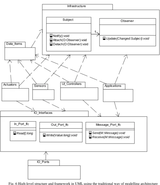
Traditionally the architect would have documented the architecture according to these design principles with a high level structure and a support framework in UML together with a set of rules expressed informally in text. This is exemplified with the UML model in Fig. 6 accompanied by a set of textual architectural design rules, such as the ones below the figure.
Infrastructure Subject Notify():void Attach(O:Observer):void Detach(O:Observer):void Observer Update(Changed:Subjec t):void 11 IO_Interfaces Message_Port_Ifc Send(M:Message):void Receive(M:Message):void In_Port_Ifc Read():long Out_Port_Ifc Write(Value:long):void Data_Items IO_Ports
Actuators Sensors UI_Controllers Applications
Fig. 6 High-level structure and framework in UML using the traditional way of modelling architecture
Some rules for Data_Items:
D1.A Data_Item is a class that reflects the state of the system or its environment
that is needed by an application. The intention is that the set of Data_Items shall be stable over time.
D2.A Data_Item shall inherit Infrastructure::Subject.
D3.A Data_Item shall be defined in the Data_Items package.
D4.The only public operations of a Data_Item shall be set and get operations to read
and write data stored by the class.
D5.A Data_Item may be a composition of Data_Items.
D6.A set operation for a Data_Item shall always end by calling its Notify operation.
S1. A sensor is typically responsible for reading the value from a physical sensor scaling it and writing the value to a Data_Item. Some sensors may however not be connected to a physical sensor but use indirect measures such as heating effect and time to estimate a value to write to the Data_Item.
S2. A Sensor shall be defined in the Sensors package.
S3. A sensor may inherit Infrastructure::Observer to be able to react to changes in
Data_Items, for instance to activate or deactivate itself.
S4. A sensor may only have associations to In_Port_Ifc and Data_Items. These
associations shall only be navigable from the sensor.
S5. A sensor may not have any public operations or attributes.
S6. A sensor shall update its Data_Item periodically.
In addition there would be corresponding rules for Actuators, UI_Controllers, Applications and IO_Ports.
3.2 Modelling the architecture according to our approach
In our approach, instead of using informal text, the architectural design rules are modelled in UML. Since UML (and any other OO language) is well suited to define
structural relationships (such as for instance “every country has one capital city” used in
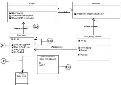
many introductory courses in OO), this can be done in a straightforward way for rules such as the ones in the previous section. Using this approach the architectural rules for Data_Items above can be modelled as exemplified in Fig. 7. In the figure it is indicated how each rule is modelled by the Dx labels. For example the rule D2, stating that a Data_Item shall inherit Subject, is modelled by associating a Data_Item to one Subject with an association stereotyped with <<Generalization>>. A major principle is that nothing that is not explicitly allowed is forbidden so a Data_Item may not have any association other than compositions to other Data_Items and may not inherit anything except a subject class.
We call the model where we model the architectural rules the architectural rules
model. It is important to realize that the classes in this model are at the meta-level of the classes of the system model; that is, they define different kinds of classes and constrain them. For instance, the association between Subject and Observer in Fig. 7 means that a Subject kind of class shall have any number of Observer kind of classes. An operation or an attribute in a class in this model means that a class of the corresponding kind in the system model must have an operation or attribute with the same characteristics as this operation or attribute. To allow for variations, wild cards can be used in attribute and operation definitions, where”@” or “%” stands for any character sequence and “%” has the additional meaning that an element with “%” in its name may be repeated any number of times, including zero. A full definition of the constructs of the architectural rules model is presented in section 5.
Data_Item_Observer $%:@ $%(%:@):@ $ev%() Abstract Data_Item $%:@ $Set_%(%:@):void $Get_%(%:@):void $Get_%():@ $%(%:@):@ * * «Association» * * * * «Association» * * «Association» * * 1 * Data_Items «Package» 1 * «Generalization» 0..1 Observer $Update(Changed:Subject):void «Generalization» 0..1 «Generalization» 1 «Generalization» 1 Subject $Notify():void $Attach(O:Observer):void $Detach(O:Observer):void 1 1 «Association» 1 1 «Association» 1 1 «Association» $Set_%(%:@):void «Primitive Operation» @ Notify(); D2 D3 D4 D5 D6
Fig. 7 Architectural design rules for Data_Items modelled according to our approach
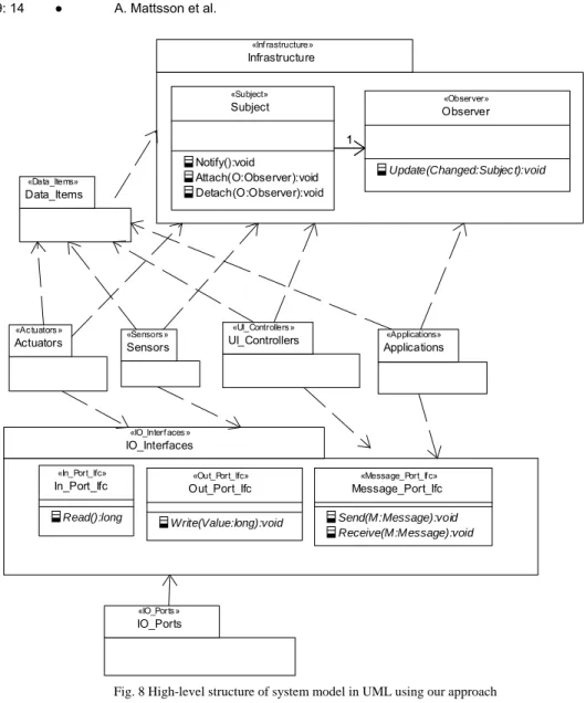
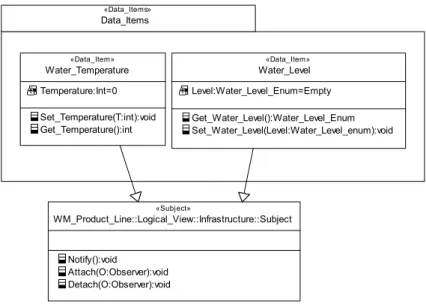
In the system model we use UML stereotypes to show the kind, corresponding to the classes in the architectural rules model, of an element. For example, in Fig. 8 it can be seen that the class Subject has the stereotype <<Subject>> meaning that it has to comply with the constraints defined by the Subject class in the architectural rules model. Fig. 8 shows the high-level structure and framework classes modelled in the system model by the architect. The only difference to the one in Fig. 6 modelled according to traditional approach is the stereotypes attached to the packages and classes. Since the architect models the high-level structure of the system, the rules restrict the developers as to which stereotypes to use in which package. For instance, in a package with stereotype <<Data_Items> all classes must have the stereotype <<Data_Item>>. Fig. 9 shows a number of Data_Items modelled in the system model following the rules of the architectural rules model in Fig. 7. Any violations to the rules are automatically detected and reported by the tool built as part of our case study, described in section 6.
Infrastructure «Inf rastructure» Subject «Subject» Notify():void Attach(O:Observer):void Detach(O:Observer):void Observer «Observer» Update(Changed:Subjec t):void 11 IO_Interfaces «IO_Interf aces» In_Port_Ifc «In_Port_Ifc» Read():long Out_Port_Ifc «Out_Port_Ifc» Write(Value:long):void Message_Port_Ifc «Message_Port_If c» Send(M:Message):void Receive(M:Message):void Data_Items «Data_Items» IO_Ports «IO_Ports» Actuators «Actuators» Sensors «Sensors» Applications «Applications» UI_Controllers «UI_Controllers»
Data_Items «Data_Items» Water_Temperature «Data_Item» Temperature:Int=0 Set_Temperature(T:int):void Get_Temperature():int Water_Level «Data_Item» Level:Water_Level_Enum=Empty Get_Water_Level():Water_Level_Enum Set_Water_Level(Level:Water_Level_enum):void WM_Product_Line::Logical_View::Infrastructure::Subject «Subject» Notify():void Attach(O:Observer):void Detach(O:Observer):void
Fig. 9 Part of the detailed design for the Data_Items package in the system model
An interesting observation in this example is that rule D1 is not modelled. The reason is that it is too vague to be formalized; it requires the developer to exercise judgement to follow it. In our experience there are these kinds of architectural rules in most systems so 100% automation of the architectural reviews is not a realistic goal. Nevertheless, we should be able to model and automatically enforce a majority of the architectural rules, something which should have a major impact on development efficiency.
4. RESEARCH APPROACH
There were three objectives of this research motivated by the lack of a satisfactory solution on how to model architectural design rules and the need for automation of the enforcement of these in a practical situation as discussed in section 2:
1. Define an approach for modelling architectural design rules in UML
2. Verify that the approach is stringent enough to be automated
3. Demonstrate that the approach is applicable to a real development project
To achieve the first objective, that of defining the approach, a systematic literature review presented in section 2 was performed. The approach adopted was based on the findings of the literature review, and was refined based on the activities undertaken to achieve the second and third objectives above.
The second objective, to verify that the approach could be automated, was addressed by developing a tool to automatically check that a system fulfilled the architectural rules specified according to the approach. In addition a MOFScript transformation that transforms architectural rules defined according to our approach to OCL constraints in an architectural rules profile has been defined. This MOFScript transformation can be found in appendix A.
To achieve the third objective, that of demonstrating the applicability of the approach, the architectural design rules from an existing, previously developed system, were modelled according to the approach. The goal of this activity was to establish the degree
to which it enabled modelling of the architectural design rules. Specifically, we searched for answers to the following two questions:
1. To what extent could the specified rules be modelled?
2. Were there certain kinds of rule that could not be modelled and if not, why not?
The system was selected based on the following criteria:
1. The system had to have been developed using MDD.
2. The system had to be an existing real system of significant size and with a
sufficient functionality to make it generally representative as a real-world embedded system.
3. The architecture, including the architectural design rules, had to be documented
to a level where it could be interpreted by the research team.
4. The research team had to have good access to people who had first-hand
knowledge of the architecture, to be able to see beyond the documentation and to be able to resolve any ambiguities.
The selected system, fulfilling these criteria, was a software platform for digital TV set
top boxes for the DVB1 standard. The system had been developed by a project which had
been studied in an earlier case study by the research team, reported in [Mattsson et al. 2009], which meant that the team had good insight into the case. It was developed using the modelling tool Rhapsody (version 4.x) from Telelogic [Telelogic], with all code generated from UML models in the tool, using C++ as the action code language. The size of the software platform was approximately 350,000 eLOC in C++ and the effort to develop it was about 100 person years over a 24 month period. The architecture was documented partly in the system model and partly in one manually written document. The system model contained a high-level package structure and a framework of classes supporting the architectural design rules. The document contained the architectural design rules. Finally, the researchers had first-hand knowledge of the architecture since the primary author of this paper was the technical manager of the project, responsible for work practices and tools. The architecture was however developed by two other persons acting as architects.
The study was conducted by a systematic walkthrough reviewing the rules from the architectural document in several iterations, gradually transforming them to modelling constructs according to our approach.
5. AN APPROACH TO MODELLING ARCHITECTURAL DESIGN RULES
In this section we present the definition of the approach for modelling architectural design rules that was developed in response to our first research objective.
As motivated in section 4 our approach is based on transforming design rules modelled in an architectural rules model, using UML, to a UML profile that are applied to the system model. The implication is that our approach to modelling architectural design rules can be reduced to a set of transformations from constructs in the architectural rules model to stereotypes with constraints in a UML profile, hereafter referred to as the architectural rules profile. Therefore our approach is defined using such a set of transformations. In this section we present these transformations in an informal
1
descriptive way, a formal definition in the form of a MOFScript transformation to a UML profile and OCL constraints can be found in appendix A.
The transformations are divided into two subsets, a general, complete transformation set and an additional UML specific transformation set. The first transformation set is general in the sense that it is applicable to any meta-model modelled in MOF, not only UML models. It is also complete in the sense that it allows us to constrain any construction of any modelling language defined in MOF. However, using only these general transformations it is still hard to model certain types of architectural rules commonly needed for UML models, for example rules restricting UML associations. To ease the modelling of such rules, the additional UML specific set of rules is needed. This transformation set is, however, not complete so the fundamental set is still needed for completeness.
All examples illustrating the transformations in this section are taken from the washing machine example introduced in section 3.
5.1 General transformations
This section defines a set of transformations from an architectural rules model to an architectural rules profile defining constraints for types of classes in a system model. The transformations are applicable to all MOF based languages not just UML. The definitions refer to the generic architectural rules model in Fig. 10 where C1 and C2 are replaced with class names, M1 and M2 replaced with stereotypes, R1 and R2 are replaced with role names, SR1 and SR2 are replaced with stereotypes and Mu1 and Mu2 are replaced with multiplicities. In the transformations below the following conventions are used:
− References to terms defined in the generic architecture model in Fig. 10 are in
italics.
− The phrase “<<Cx>> element” shall be interpreted “element of stereotype Cx”
or, if Mx equals “metaclass”, “element of meta-class Cx” (where x is 1 or 2).
− The term “meta-class” in the transformations refers to a meta-class of the
modelling language that is constrained, for instance the meta-model for UML.
− The term “meta-model” in the transformations refers to the meta-model of the
modelling language that is constrained, for instance the meta-model for UML. <<M1>> C1 <<M2>> C2 <<SR1>> R1 <<SR2>> R2 Mu2 Mu1 A:T C3
Fig. 10 A generic architectural rules model used in the definition of the transformations
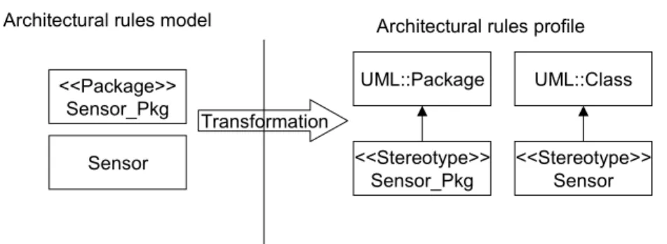
T1. A class named C1 with the stereotype M1 is transformed into a stereotype
named C1 extending the meta-class M1 unless transformation number T2 below
applies. If M1 is undefined then “Class” is assumed; see Fig. 11 for an example.
<<Package>> Sensor_Pkg
<<Stereotype>> Sensor_Pkg UML::Package
Architectural rules model Architectural rules profile
Transformation
Sensor <<Stereotype>>
Sensor UML::Class
Fig. 11 Example of transformation according to transformation T1.
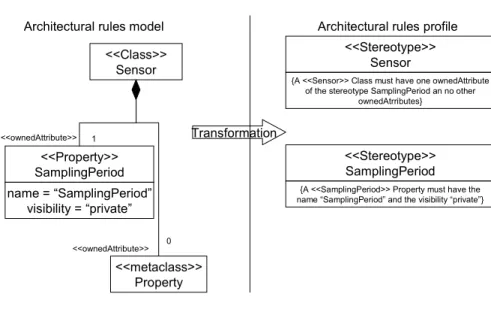
T2. If M1 equals “metaclass” then C1 represents the class C1 in the language
meta-model (i.e. the UML meta-meta-model) and is not transformed into anything in the profile. This can be used to specify constraints in other stereotypes in respect to these meta-classes, see Fig. 12 for an example.
T3. If SR2 is the role in the language meta-model on the far end of an association
from the meta-class of C1 to the meta-class of C2 then the multiplicity of R2 for
a <<C2>> element shall be constrained to Mu2 in stereotype <<C1>>.
An example is shown in Fig. 12 where a <<Sensor>> class is constrained to only have one <<SamplingPeriod>> attribute and no other attributes.
It is allowed to have several association ends matching the same meta-model association end. In that case the multiplicity of the end with the most narrow
type scope is applied for a certain <<C2>> element. In the example in Fig. 12
for example the multiplicity is “1” for an attribute with the stereotype <<SamplingPeriod>, since this multiplicity is only applicable to attributes with stereotype <<SamplingPeriod>> and the multiplicity of 0 is applicable to all attributes.
<<Class>> Sensor Architectural rules model
<<metaclass>> Property <<ownedAttribute>> 0 <<Property>> SamplingPeriod name = “SamplingPeriod” visibility = “private” 1 <<ownedAttribute>>
Architectural rules profile <<Stereotype>>
Sensor
{A <<Sensor>> Class must have one ownedAttribute of the stereotype SamplingPeriod an no other
ownedAtrributes}
<<Stereotype>> SamplingPeriod
{A <<SamplingPeriod>> Property must have the name “SamplingPeriod” and the visibility “private”}
Transformation
Fig. 12 An example of using transformation T2, T3 and T4.
T4. If the name of an attribute A matches the name of an attribute of class M1 in the
meta-model then it is transformed into a constraint on that attribute on allowed values. The value of the attribute is constrained to match a regular expression specified as the default value of the attribute.
An example is shown for the attribute name in Fig. 12 where the name of the <<SamplingPeriod>> attribute is constrained to be “SamplingPeriod”.
T5. If no match is found for A then A is transformed into an attribute A of the
stereotype (tag-definition), thus defining a tagged value to be set in the model element where the stereotype is applied.
T6. Any OCL constraint in the context of a class C1 is copied into the architectural
rules profile with the context of stereotype C1. This means that the constraints
shall be written the same way as when defining stereotypes directly in the profile.
Even though OCL expressions, as discussed in section 3, are not suitable for modelling architectural design rules in general, there is a need for them to express for instance constraints on combinations of rules. For example, if we would like to specify that a <<Sensor>> class has either a <<Sample>> operation or a <<Trig>> operation it could be done like this:
context Sensor
inv: self.base_Class.ownedOperation.extension_Sample.size()=1 xor self.base_Class.ownedOperation.extension_Trig.size()=1
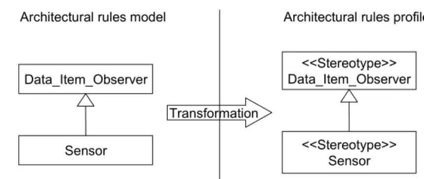
T7. A generalisation relationship from a class C3 to a class C1 in the architectural
rules model is transformed to a generalisation from stereotype <<C3>> to stereotype <<C1>> in the architectural rules profile as exemplified in Fig. 13.
This means that stereotype <<C3> inherits all constraints from stereotype
Data_Item_Observer
Sensor
Architectural rules model Architectural rules profile
<<Stereotype>> Data_Item_Observer
<<Stereotype>> Sensor Transformation
Fig. 13 An example of using transformation T7
This set of transformations is general and complete in the sense discussed below:
− The transformation set is general: These transformations allow us to use a
sub-set of UML to constrain the usage of any modelling language defined in MOF since the transformations only assume that the modelling language is defined using MOF and do not assume anything about the content in the meta-model (i.e. the UML meta-meta-model).
− The transformation set is complete: A model is an instance of its meta-model,
which means that any model element is an instance of a class in the meta-model. The only things that may vary between two models of the same meta-model defined in MOF is the number of instances of each meta-class, the values and multiplicities of the meta-class attributes and the links between the instances. Since these transformations allow us to constrain allowed values and multiplicities for attributes and constrain the types and multiplicities of associations, the set of transformations is complete in the sense that it allows us to constrain anything that can vary between different models of a certain meta-model defined in MOF.
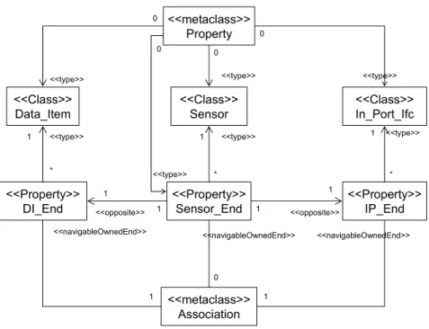
By only using these transformations it is, however, still too complex to model constraints on some common UML constructs such as associations, attributes, operations and state machines. For example, Fig. 14 shows how the simple example rule S4 introduced in section 3 is modelled according to these transformations.
<<Class>> Data_Item <<Class>> Sensor <<Property>> DI_End <<type>> <<navigableOwnedEnd>> <<type>> <<metaclass>> Association * * <<type>> 0 0 <<type>> 1 <<navigableOwnedEnd>> 0 <<opposite>> 1 1 <<Class>> In_Port_Ifc <<Property>> IP_End 1 <<opposite>> <<navigableOwnedEnd>> 0 <<type>> <<type>> * 1 1 1 1 1 <<type>> 0 <<Property>> Sensor_End <<metaclass>> Property
Fig. 14 Capturing an association constraint in a meta-model using the general transformations.
To overcome this problem we have defined a set of additional transformations that makes it considerably simpler to specify certain constraints on UML models, common within the embedded software domain; these are described in the next section.
5.2 Additional UML specific transformations
This section defines a set of transformations in addition to the general ones defined in the previous section. The purpose of these transformations is to make it simpler to describe frequently needed architectural rules on UML models that are hard to describe using only the general transformations. These transformations override the general transformations in cases where both a general and an additional UML specific transformation apply. The definitions refer to the generic architectural rules model in Fig. 15. In the definitions the following conventions are used:
− References to terms defined in the generic architecture model in Fig. 15 are in
italics.
− The phrase “<<Cx>> element” where x is 1 or 2 shall be interpreted “element of
stereotype Cx” or, if Mx equals “metaclass”, “element of meta-class Cx”.
<<M1>> C1 <<M2>> C2 R1 R2 Mu2 Mu1 <<MA,S1…Sn>>
Constraints on stereotype C1 is defined according to the following:
T8. If M1 equals “Package”and aggregation of R2 is “composite”:
A <<C1>> package is constrained to contain Mu2 number of <<C2>>
elements. The visibility of these elements shall be the visibility of Mu2. Also, a
<<C1>> package is not allowed to have any packagedElements unless
explicitly allowed in the model. This transformation makes it easy to model rules on package containment. An example is shown in Fig. 16.
Architectural rules model
<<Package>> Data_Items
<<Class>> Data_Item
*
Architectural rules profile
Transformation
<<Stereotype>> Data_Items
{A <<Data_Items>> Package may contain any number of <<Data_Item>> Classes and no
other elements}
Fig. 16 Example of rules on package containment.
T9. <<C1>> elements are only allowed to have the associations, dependencies,
generalizations and realizations explicitly allowed.
T10. If MA equals “Association”:
A <<C1>> element shall be associated with Mu2 number of <<C2>> elements. The association ends shall have the same navigability, aggregation (none, shared
or composite) and visibility as R1 and R2. The association ends shall also have
qualifiers according to the qualifiers of R1 and R2. The name and type of these
shall be according to the transformations for attributes specified below. The
association shall have the stereotypes S1 to Sn. This transformation makes it
easy to formulate rules on associations; as for instance, the example rule introduced in section four can now be modelled as shown in Fig. 17. Contrast this with the model in Fig. 14 to see the difference from modelling using only the fundamental transformations.
Data_Item
Sensor * *
<<Association>>
Architectural rules model Architectural rules profile
Transformation
<<Stereotype>> Sensor
{A <<Sensor>> Class shall have any number of associations only navigable to a <<Data_Item>>
class}
<<Stereotype>> Data_Item
{A <<Data_Item>> Class shall have any number of associations only navigable from a <<Sensor>>
class}
Fig. 17 Example of rules on associations
T11. If MA equals “Dependency”, “Generalization” or “Realization” and the
association is only navigable from C1 to C2:
A <<C1>> element shall have a relationship according to MA to Mu2 number of <<C2>> elements with stereotypes S1 to Sn.
Examples of these kinds of transformation are shown in Fig. 18.
In_Port_Ifc Observer
Architectural rules model Architectural rules profile
Transformation Data_Item_Observer In_Port <<Generalization>> <<Realization>> 0..1 1 <<Stereotype>> Data_Item_Observer {A <<Data_Item_Observer>> Class shall inherit zero to one
<<Observer>> classes}
<<Stereotype>> In_Port
{An <<In_Port>> Class shall realize one <<In_Port_Ifc>>
Class}
Fig. 18 Example of rules on generalizations, dependencies and realizations
T12. If there are attributes A of C1 that starts with $ then:
a. All parts of the definition of an attribute of a <<C1>> class must match the corresponding part of an A, where the wild card characters “@” and “%” in any part of the definition of A can be replaced with any character sequence. Parts of A not specified (as for instance default value for Sampling_Period in Fig. 19) are unconstrained.
b. All A must be matched by one attribute in a <<C1>> class. An exception to this is if the name of A contains the wild card character “%”; in this case any number of matches (including zero) is allowed.
c. If the name of a type of A is identical to the name of a class C in the
architectural rules model then the type of a matching attribute must be a <<C>> element.
This transformation is exemplified in Fig. 19.
Architectural rules model Architectural rules profile
Transformation Sensor $-Sampling_Period : int $% : @ <<Stereotype>> Sensor {A <<Sensor>> Class must have one private attribute named “Sampling_Period” with a type named “int” and any number of other attributes with any visibility, name and type}
Fig. 19 Example of rules on attributes.
T13. If there are operationsO of C1 that start with $ then:
a. All parts of the definition of an operation of a <<C1>> class must
match the corresponding part of an O, where, for each part of the definition, the wild card characters “@” and “%” can be replaced with any character sequence. Parts of O not specified (as for instance parameter directions for operations in Fig. 20) are unconstrained.
b. This requirement holds for all parts of the definition of O defined in the
UML meta-model, such as for instance opaque behaviour specified for the operation.
c. The character “%” in a parameter name means that the definition of this
parameter can be repeated any number of times, including zero. In these parameter definitions “%” can be replaced with any character sequence.
d. If the name of the type of O or a parameter of O is identical to the name
of a class B in the architectural rules model then the type of matching operations or parameters in the <<C1>> class must be of a <<B>> Class.
e. All O must be matched by one operation in a <<C1>> class. An
exception to this is if the name of O contains the wild card character “%”; in this case any number of matches (including zero) is allowed. This transformation is exemplified in Fig. 20.
Architectural rules model Architectural rules profile Transformation Subject $+Attach(O:Observer) Observer $Set_%(%:@) { @ Notify(); } Data_Item $+Set_%(%:@) <<Stereotype>> Subject {A <<Subject>> Class shall have one public operation named “Attach” with one parameter named “O”. The type of this parameter shall be a Class stereotyped <<Observer>>. The operation shall have no return value}
<<Stereotype>> Data_Item {A <<Data_Item>> Class shall have any number of public operations who's name begins with “Set_” . The operations can have any parameters of any type. The operations shall have no return value. The operations shall have an opaque behaviour specification ending with “Notify();”}
Fig. 20 Example of rules on operations
T14. If C1 has a state machine then a <<C1>> class must have a state machine
where there for each region in C1 shall be an identical region in the <<C1>>
class. The wild card character “@” may be used in the transition definitions in
C1 and shall then be matched with any text string in the corresponding
transition in the state machine of a <<C1>> class. It is allowed to have
additional regions in the state machine of a <<C1>> class.
This transformation is exemplified in Fig. 21. In this example a <<Sensor>> class is constrained to have a top region exactly matching the state machine for Sensor in the architectural rules model, which in effect forces Sensor classes to call the operation Sample() periodically with the period specified by the attribute Sampling_Period. A <<Sensor>> class may have additional behaviour specified in parallel regions to the one specified in Sensor.
Architectural rules model Architectural rules profile
Transformation Sensor
<<Stereotype>> Sensor
{A <<Sensor>> Class shall have a state machine with a top level region with a state machine that is a copy of the state machine of Sensor}
stm Sensor
Sampling
after(Sampling_Period)/Sample()
Fig. 21 Example on rules on state machines
These additional UML specific set of transformations make it easy to specify constraints on for instance how different kinds of classes may be associated. To illustrate, let us revisit the previously used example in section 4:
A Simulator class may only have associations to a maximum of five Data_Item classes. These associations shall only be navigable from a Simulator class to a Data_Item Class.
This rule may now be modelled according to Fig. 222, which is very close to the simple
(but only indicative) model in Fig. 5, and significantly less complex than the model in Fig. 14, where only the general transformations were used.
Data_Item * Sensor * In_Port_Ifc
<<Association>> <<Association>>
Fig. 22 Capturing the architectural design rule using the specialised additional transformations.
These additional transformations also make it simple to specify other common constraints such as on package structure and on interfaces and the behaviour of classes. This is further illustrated in section seven.
2
Actually, in our example introduced in section 3 Sensor would instead inherit the rule to be allowed to have associations to <<Data_Item>> from Data_Item_Observer shown in Fig. 7
6. AUTOMATING THE APPROACH
In this section we present the tool for automating enforcement of architectural design rules that was developed in response to our second research objective (which was to verify that the approach was stringent enough to be automated).
To provide a proof-of-concept of the feasibility of automating the approach, a tool was built making it possible to automatically check that a system conformed to rules modelled according to the approach.
There were several options when considering tool support for the approach:
− The rules could be enforced as a separate test, reporting violations.
− The rules could be continuously enforced during modelling giving the
possibility of guiding the developer during development and if desired preventing the modeller from breaking the rules.
− In both cases the modelled rules could either first be transformed into OCL
constraints in a UML profile, which would then be enforced, or they could be directly enforced on the system model.
An important thing to consider was how to make it as easy as possible for an organisation to adopt the new method and tool. For an organisation that is already using modelling tools it would be a big advantage if they did not have to change their modelling tools. New tools would incur cost in purchase, training and transferring models to the new tools. In our case the organisation was using the Rhapsody modelling tool. This was also the tool that had been used in building the system for which we intended to remodel the architectural design rules. Therefore we needed a tool that could take Rhapsody models both for the architectural design rules and for the system models. Considering this we built the tool as a plug-in to the Rhapsody tool validating the system model directly against the modelled rules for the following reasons:
1. To make a plug in to the modelling tool that continuously checks the model
would be harder than to make a stand-alone checker, would be harder to move to another tool, and would risk increasing the response time when modelling.
2. Although open-source stand alone tools for OCL checking are available, making
an OCL generator and integrating an OCL checker in Rhapsody was considered at least as hard as our current approach and in addition would increase the risk since we would be relying on another tool.
The tool is built in C++ and is currently limited to reading Rhapsody [Telelogic] models, both for architectural rules and for the system model. The tool is designed so that there are no dependencies to the model reader component from any other parts in the tool. This makes it a relatively small task to adapt the tool to another modelling tool. The total effort to build the tool was approximately 200 man hours; the estimated effort to build another model reader is about 40 man hours. A screenshot of the tool is shown in Fig. 23 where the output from the validator is shown in the text window in the bottom. The text refers to the violations in the Water_Level class in respect to the architectural rules in Fig. 7.
Fig. 23 Screenshot of tool
7. MODELLING ARCHITECTURAL DESIGN RULES OF AN INDUSTRIAL STRENGTH SYSTEM
In this section we present the findings of a case study performed in response to our third research objective (which was to demonstrate that the approach was applicable to a real development project).
To demonstrate the applicability of our approach to a real problem we modelled the architectural design rules from an already developed system according to our set of
transformations3. The mapping between the original architectural rules and the models was documented in a text table. A part of this table is shown in Table 1. The rules could be classified into three categories: structural, behavioural and judgmental. Structural rules specified structural constraints such as rule 4.1, 4.2, 6.7 and 8.1 in the table. Behavioural rules specified constraints on behaviour such as rule 9.16 in the table. Judgemental rules were rules where the developer had to exercise judgement to follow the rule; 3.2 is an example of such a rule in the table. There were 66 rules in total; eight of these could not be modeled. These were all judgmental and therefore inherently impossible to formalize. The rules typically consisted of one or two sentences, where the sample rules in Table 1 are representative.
Table 1. A subset of the full table which had mappings between all the original architectural design rules and resulting modelling constructs
Id Original rule (Quotation) Modelreference Used
Transform- ations
3.2 “Functionality specific to a PAPI requirement shall be kept in this layer unless it is reusable for another PAPI or applicable to DVB standard. In this case it shall be placed in CMP or CMD.”
-
- 4.1 “All coupling between arcComponents
shall be loose in the sense not statically linked”
Handled by only allowing associations from a component to an Interface that
is realized by an arcComponent. T9, T10, T11 4.2 “All associations between
arcComponents shall be navigable from the client to the server (user to the resource)”
User/Resource association from mComponent to mCompIfc
T10 6.7 “In the case of a component locked to a
specific arcComponentUser, it is the responsibility of the locker to allow only one thread at a time to access the component.”
This is ensured by the implementation of the enforced implementation of the operations of the
mLockableComponent.
T13 8.1 “All locked components shall inherit
the same base class, arcLocked.”
Generalization from mLockableComponent to
marcLockableComponent, there is only one instance of
marcLockableComponent allowed, in an Architecture_Pkg and finally there is only one Architecture_Pkg with only one marcLockableCompionent class in
the Systemmodel. T8, T11 9.16 “Transmission events and exceptions
initiated by a Write() shall be reported back to the arcPortUser via the TxDone() call.”
A Write operation is forced to always end with a call to TxDone
T13
The average size of the rules was 17 words with a maximum of 38 words and a minimum of four words. Table 2 shows for each transformation the number of rules it was used to model (Usage frequency) and the percentage of architectural review remarks
3
Note that in a real case the architectural rules model would be modelled as a natural part of the architectural design and not as a separate activity. Normally there would not even be any textual expression of the rules, only the architectural rules model.
in the review protocols that related to these rules (Violations). The transformations T1 and T9 are marked as not applicable since T1 is always used and T9 is always used in conjunction with T10 and T11. In total there were 1563 remarks in 120 architectural review protocols. The table shows that the most commonly used rules were T8, T10, T11 which specify structural rules on package containment, associations, relations and generalizations, and T13 which specify rules on the operations (i.e. the interafce) of classes. Not surprisingly, these rules are also subject to most violations.
Table 2. Usage freqency and violation percentage for each transformation
T1 T2 T3 T4 T5 T6 T7 T8 T9 T10 T11 T12 T13 T14
Usage
frequency N.A. 2 3 2 0 2 1 10 N.A. 13 22 6 17 5
Violations
(%) N.A. 3,37 4,46 2,92 0,00 3,19 1,55 15,38 N.A. 20,73 34,84 8,55 25,29 9,57
Both the architectural rules model and the architectural parts of the system model were captured in the Rhapsody modelling tool (version 7.2). Fig. 24 - Fig. 26 show parts of these models. Fig. 25 shows the subsystems modelled as packages in the system model. This level of the system model is owned by the architects. The stereotypes of these packages are defined in the architectural rules model partly shown in Fig. 24. In this model you can see, for instance the architectural rules that a <<Subsystem>> package (that is, a package with the stereotype <<Subsystem>>) shall contain a number of <<Component_Pkg>> packages and one <<mRegistry>> class. You can also see that a <<Component_Pkg>> shall contain exactly one <<mComponent>> class that must inherit a <<marcComponet>> class (defined by the architects in the architecture package in the system model.). In Fig. 26 an example of a small component in the system model is shown, following the architectural rules defined in the architectural rules model.
Subsystem «Package» * Component_Pkg «Package» * Class «metaclass» * - Unit * - Unit mComponent $%:@ $mComponent $%(%:@) «Association» 1 * - Unit 1 -«Association» 1 * - Unit «Association» 1 * - Unit 1 -1 mRegistry «Association» * 1 «Association» * 1 arcComponentUser «Dependency,Friend» 1 1 «Association» * 1 «Association» * 1 «Association» * 1 arcComponentUser «Association» * 1 arcComponentUser «Dependency,Friend» 1 * + * + mCompIfc «Interface»
$%(%:@) Resource* «Association» User1
«Realization» * «Association» 1 * User Resource «Association» 1 * User Resource «Association» 1 * User Resource «Realization» * «Gereralization» 1 «Gereralization» 1 marcComponent marcLockableComponent * + Parameter «Dependency,Usage» * «Dependency,Usage» * * + «Dependency,Usage» * «Dependency,Usage» * mLockableComponent $CurrentUser:arcComponent $%(Locker:arcComponent,%:@):@ «Gereralization» 1 «Gereralization» 1
HAL «External» OSAL «External» PAPI «Subsystem» CMP «Subsystem» CMD «Subsystem» Arc hitecture «Architecture_Pkg»
Fig. 25 Top level of system model.
PAPI «Subsystem» PAPI_Regis try «mRegistry» itsClockDevice : ClockDevice 1 «mComponent» ClockDevice_Pkg «Component_Pkg» ClockDevice_Ifc «mCompIf c» SetTime(T:Time) GetTime(Receiver:TimeReceiver... 1 1 TimeRec eiver_Ifc «mCompIf c» TimeIs(T:Time) ClockDevice «mComponent» ClockDevice() «Realization» «Friend» * 1 1 «Realization» «Friend» * System_model::Architecture::arcComponent «marcComponent»
![Fig. 5 Capturing the architectural design rule example using the approach suggested in [Fuentes-Fernández and Vallecillo-Moreno 2004]](https://thumb-us.123doks.com/thumbv2/123dok_us/10980516.2985953/8.756.105.640.94.751/capturing-architectural-example-approach-suggested-fuentes-fernández-vallecillo.webp)