ISSN: 2088-8708, DOI: 10.11591/ijece.v10i1.pp617-625 617
Direct torque control of IM using PID controller
Ali Najim Abdullah, Mohammed Hassan Ali
Department of Electrical Power and Machines Egineering, College of Engineering, University of Diyala, Iraq
Article Info ABSTRACT
Article history: Received Nov 6, 2018 Revised Apr 11, 2019 Accepted Sep 28, 2019
Direct torque control "DTC" technique is one of a high performance control system of an AC motor drive, which was proposed after the vector oriented control scheme during the resent 25 years. It has been developed rapidly for its concise system scheme, transient and dynamic performance. The DTC mechanism consists of voltage vector selection table, two hysteresis comparators and two estimator’s one for stator flux and another for electromagnetic torque. DTC is directly control torque and flux by using Voltage Source Inverter VSI, space vector and stator flux orientation and indirect speed regulated. A several control techniques can be used for improving the torque and flux performance. In this paper, the DTC with Proportional-Integral-Derivative (PID) controller used to improve the starting and dynamic performance of asynchronous motor AM, which gives good torque and flux response, best speed control and also minimize the unacceptable torque ripple. The mathematical model of DTC with PID controller of 3-phase induction motor IM are simulated under Matlab-Simulink. Therefore, the DTC based on PID controller has good performance of IM compared to classical DTC for starting, running state and also during change in load.
Keywords:
3-phase induction motor drive Direct torque control
PID controller Voltage space vector
Copyright © 2020 Institute of Advanced Engineering and Science. All rights reserved.
Corresponding Author: Mohammed Hasan Ali,
Departement of Electrical power and Machins Engineering, Collage of Engineering,
University of Diyala, Baqubah, Diyala, Iraq.
Email: [email protected]
1. INTRODUCTION
Asynchronous motors are widely used for industrial purposes due to many advantages such as more reliability, low cost, simple in construction, high efficiency, ruggedness and low maintenance compared with other drives [1, 2]. According to more industrial applications of IMD, this demands a modern control to get better performance characteristic at starting and steady-state conditions. This control can be achieved by applying a several new techniques [3].
DTC is one of these control techniques can be gives a high performance in application. Takahashi and Noguchi were provided “Direct torque control” DTC for improving starting and dynamic performance of the machine [4, 5]. The DTC strategy using the hysteresis comparator based on voltage switching state can be easy implementation and simple structure. The DTC performance depends on the error between the references values and measured actual values of stator flux and electromagnetic torque to get more acceptable response for flux and torque [6, 7].But the problem which appear when applied classical DTC to induction motor is high ripple in electromagnetic torque due to produce a harmonic [8].
In this paper the modeling of 3-phase induction motor drive, voltage source inverter, switching state vector and Direct Torque Control DTC concept are discussed. The transient and steady state performances of induction motor are analyzed by using classical DTC and DTC with PID controller. These method controls are simulated using Computer Simulink. Also the results have been compared [9]. Therefore, the results show
that the DTC with PID controller has many merits simple realization, fast speed control, best starting and running characteristics over the classical DTC. All results are getting by using Matlab simulation [10].
2. MATHEMATICAL MODEL OF A 3-PHASE INDUCTION MOTOR DRIVE
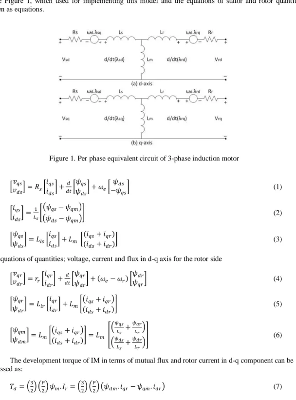
A model of three phase induction motor drive can be obtained when it is acts under normal and dynamic condition. Therefore, the variables quantities of IMD such as stator and rotor current, stator and rotor voltage, stator and rotor flux, and electromagnetism torque can be determined from this model [11, 12]. The description model of a 3-phase IMD can be represented by differential equations when the main three phase stator and rotor quantities such as current, voltage, and flux are transform to stationary frame or two axis theory frame “d-q axis” by axis transformation. A 3-phase IMD model implemented based on the stationary reference frame [13, 14]. The per phase equivalent circuit of 3-phase IMD in d-q axis is shown in the Figure 1, which used for implementing this model and the equations of stator and rotor quantities written as equations.
Figure 1. Per phase equivalent circuit of 3-phase induction motor
[𝑣𝑣𝑞𝑠 𝑑𝑠] = 𝑅𝑠[ 𝑖𝑞𝑠 𝑖𝑑𝑠] + 𝑑 𝑑𝑡[ 𝜓𝑞𝑠 𝜓𝑑𝑠 ] + 𝜔𝑒[ 𝜓𝑑𝑠 −𝜓𝑞𝑠] (1) [𝑖𝑞𝑠 𝑖𝑑𝑠 ] = 1 𝐿𝑠[ (𝜓𝑞𝑠− 𝜓𝑞𝑚) (𝜓𝑑𝑠− 𝜓𝑞𝑚) ] (2) [𝜓𝑞𝑠 𝜓𝑑𝑠 ] = 𝐿𝑙𝑠[ 𝑖𝑞𝑠 𝑖𝑑𝑠 ] + 𝐿𝑚 [ (𝑖𝑞𝑠+ 𝑖𝑞𝑟) (𝑖𝑑𝑠+ 𝑖𝑑𝑟) ] (3)
The equations of quantities; voltage, current and flux in d-q axis for the rotor side [𝑣𝑣𝑞𝑟 𝑑𝑟] = 𝑟𝑟[ 𝑖𝑞𝑟 𝑖𝑑𝑟 ] + 𝑑 𝑑𝑡[ 𝜓𝑞𝑟 𝜓𝑑𝑟 ] + (𝜔𝑒− 𝜔𝑟) [ 𝜓𝑑𝑟 𝜓𝑞𝑟] (4) [𝜓𝑞𝑟 𝜓𝑑𝑟 ] = 𝐿𝑙𝑟[𝑖𝑞𝑟 𝑖𝑑𝑟 ] + 𝐿𝑚[(𝑖𝑞𝑠+ 𝑖𝑞𝑟) (𝑖𝑑𝑠+ 𝑖𝑑𝑟) ] (5) [𝜓𝑞𝑚 𝜓𝑑𝑚 ] = 𝐿𝑚[ (𝑖𝑞𝑠+ 𝑖𝑞𝑟) (𝑖𝑑𝑠+ 𝑖𝑑𝑟) ] = 𝐿𝑚 [ (𝜓𝑞𝑠 𝐿𝑠 + 𝜓𝑞𝑟 𝐿𝑟) (𝜓𝑑𝑠 𝐿𝑠 + 𝜓𝑑𝑟 𝐿𝑟) ] (6)
The development torque of IM in terms of mutual flux and rotor current in d-q component can be expressed as: 𝑇𝑑= ( 3 2) ( 𝑃 2) 𝜓𝑚. 𝐼𝑟= ( 3 2) ( 𝑃 2) (𝜓𝑑𝑚. 𝑖𝑞𝑟− 𝜓𝑞𝑚. 𝑖𝑑𝑟) (7)
The development torque of IM in terms of stator flux and stator current in d-q component can be expressed as: Td= ( 3 2) ( P 2) ψs. Is= ( 3 2) ( P 2) (ψds. iqs− ψqs. ids) (8)
Where vqs, vds: stator voltages in quadrature and direct axes; vqr, vdr: rotor voltages in quadrature and direct axes; Rs, Rr: stator and rotor resistance; iqs, ids: stator currents in quadrature and direct axes; iqr, idr: rotor currents in quadrature and direct axes; ψqs, ψds: stator flux in quadrature and direct axes. ψqr, ψdr: rotor flux in quadrature and direct axes; Td: development torque.
3. VOLTAGESOURCEINVERTERANDSWITCHINGSTATEVECTOR
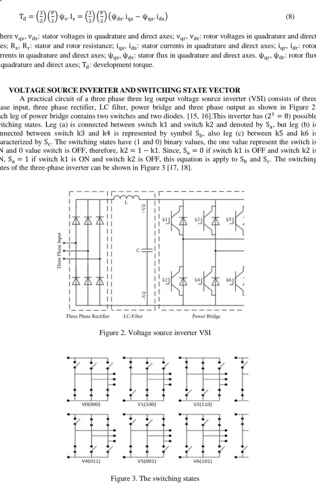
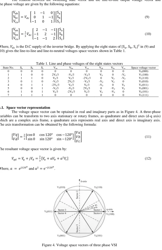
A practical circuit of a three phase three leg output voltage source inverter (VSI) consists of three phase input, three phase rectifier, LC filter, power bridge and three phase output as shown in Figure 2. Each leg of power bridge contains two switches and two diodes. [15, 16].This inverter has (23= 8) possible switching states. Leg (a) is connected between switch k1 and switch k2 and denoted by Sa, but leg (b) is connected between switch k3 and k4 is represented by symbol Sb, also leg (c) between k5 and k6 is characterized by Sc. The switching states have (1 and 0) binary values, the one value represent the switch is ON and 0 value switch is OFF, therefore, k2 = 1 − k1. Since, Sa= 0 if switch k1 is OFF and switch k2 is ON, Sa= 1 if switch k1 is ON and switch k2 is OFF, this equation is apply to Sb and Sc. The switching states of the three-phase inverter can be shown in Figure 3 [17, 18].
Figure 2. Voltage source inverter VSI
The relation between the switching state vector and the line-to-line output voltage vector and the phase voltage are given by the following equations:
[ Vab Vbc Vca ] = 𝑉𝑑𝑐[ 1 −1 0 0 1 −1 −1 0 1 ] [ Sa Sb Sc ] (9) [ Van Vbn Vcn ] =1 3𝑉𝑑𝑐[ 2 −1 −1 −1 2 −1 −1 −1 2 ] [ Sa Sb Sc ] (10)
Where, 𝑉𝑑𝑐 is the D.C supply of the inverter bridge. By applying the eight states of [Sa, Sb, Sc]T in (9) and (10) gives the line-to-line and line-to-neutral voltages space vectors shown in Table 1.
Table 1. Line and phase voltages of the eight states vectors
State No. Sa Sb Sc Van Vbn Vcn Vab Vbc Vca Space voltage vector
0 0 0 0 0 0 0 0 0 0 V0(000) 1 1 0 0 2Vd/3 -Vd/3 -Vd/3 Vd 0 -Vd V1(100) 2 1 1 0 Vd/3 Vd/3 -2Vd/3 0 Vd -Vd V2(110) 3 0 1 0 -Vd/3 2Vd/3 -Vd/3 -Vd Vd 0 V3(010) 4 0 1 1 -2Vd/3 Vd/3 Vd/3 -Vd 0 Vd V4(011) 5 0 0 1 -Vd/3 -Vd/3 2Vd/3 0 -Vd Vd V5(001) 6 1 0 1 Vd/3 -2Vd/3 Vd/3 Vd -Vd 0 V6(101) 7 1 1 1 0 0 0 0 0 0 V7(111)
3.1. Space vector representation
The voltage space vector can be optained in real and imajinary parts as in Figure 4. A three-phase variables can be transform to two axis stationary or rotary frames, as quadrature and direct axes (d-q axis) which are a complex axis frame, a quadrature axis represents real axis and direct axis is imaginary axis. The axis transformation can be obtained by the following formula:
[𝑉𝑞 𝑉𝑑] =
2
3[cos 0 cos 120° cos −120°sin 0 sin 120° sin −120°] [ 𝑉𝑎 𝑉𝑏 𝑉𝑐
] (11)
The resultant voltage space vector is given by: 𝑉𝑞𝑑= 𝑉𝑞+ 𝑗𝑉𝑑= 2 3[𝑉𝑎+ 𝑎𝑉𝑏+ 𝑎 2𝑉 𝑐] (12) Where, 𝑎 = 𝑒j120o and 𝑎2= e−j120o.
4. DIRECT TORQUE CONTROL TECHNIQUE
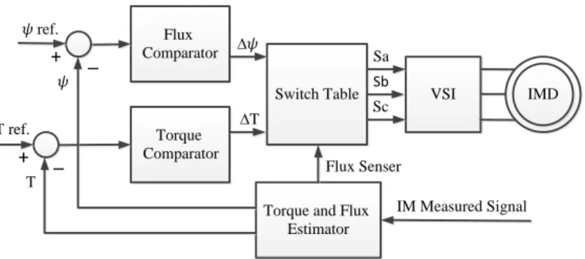
Direct torque control DTC was displayed by Takahashi and Toshihiko Noguchi since twenty five years ago. This technique is used to control the speed of 3-phase AC motor drives due to control the torque and stator flux of the machine. the DTC can be achieved by computing flux and torque of an electric motor according to only stator quantities measurable such as stator voltage and stator current of the AC motor drive. Traditional direct torque control contains two hysteresis comparators, the first hysteresis comparator for computing stator flux error and the second hysteresis comparator to estimate torque error [19, 20]. The scheme diagram of the DTC technique is constructed as in Figure 5.
The principle operation of DTC based on voltage source inverter with eight stator voltage vectors, six of them is not zero vector state and the two remained is zero vectors so as to maintain the stator flux and electromagnetic torque into desired value of a hysteresis band. The reference of voltage space vector is determined by switching table [21]. The controller in DTC is used two signals as a feedback one of them for developed torque and the second for stator flux in order to measure the torque and flux error by comparative the references value with the feedback signal. The hysteresis comparator of stator flux error has two standard levels (one and zero). The 1 state means that the stator flux is low and zero value for another condition. Also hysteresis comparator for torque error is represented by three standard levels (1, zero, -1). The 1 state is illustrate that the torque is dawn, zero value gives that the torque in acceptable rang and -1 for high value [22, 23]. VSI Switch Table Flux Comparator Torque Comparator
Torque and Flux Estimator IM Measured Signal IMD 𝜓 ref. T ref. 𝜓 T ∆𝜓 ∆T Sa Sb Sc + + Flux Senser _ _
Figure 5. The block diagram of DTC control technique
5. PID CONTROLLER [24]
Proportional-Integral-Derivative, PID, controller is broadly utilized in modern control framework. PID controller has all the essential elements: fast response on change of the controller input, increment in control flag to lead mistake towards zero and reasonable activity inside control blunder region to take out motions. Subordinate mode improve soundness of the model system and empowers increment in gain Kp, which builds speed of the controller reaction. The yield of PID controller comprises of three terms the mistake flag, the blunder vital and the mistake subsidiary. The blunder flag is registered by (13). Figure 6 demonstrates the square graph of PID controller [25]. The change capacity of PID controller is employed as:
U(s)
E(s) = Kp + Ki
S + KS (13)
Where Kp, Kd and ki are proportional, derivative, integral gains respectively and U(s) is the yield control refer to Te torque reference in control drive.
∫ Integrator Derivative Error Ki Kd Kp d/dt +++ Vector and Three Phase Invertor Te Actual Speed R ef . S p ee d PID 3-Ph. IMD +_
6. SIMULATION RESULTS
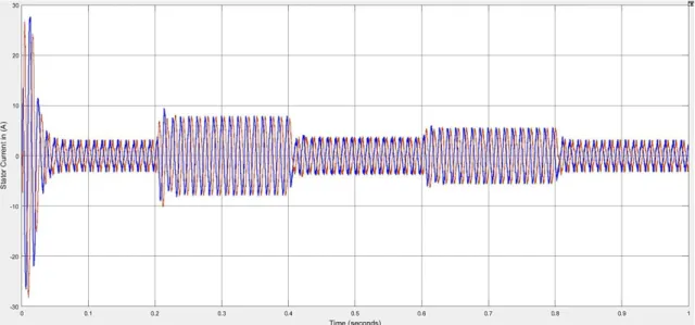
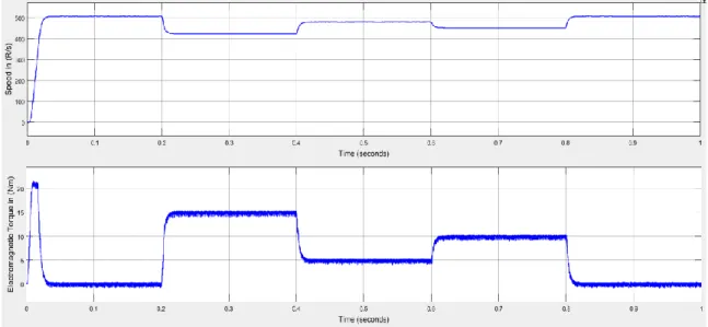
In this paper, the proposed algorithm of DTC of an IMD is investigated by using simulation in software program. In this work a several tests perform on the system so as to examination the performance characteristic of the proposed classical DTC system and DTC with PID controller. Note that at time of load change the torque and speed are not response smoothly with traditional DTC, but get better response when using PID controller in addition to the ripple in the torque is minimized. The response of the stator current is shown in Figure 7, therefor the IMD system will produce the magnetic flux as in Figure 8, and hence the rotor speed and electromagnetisms torque response of classical DTC at no load and different load disturbance is shown in Figure 9.
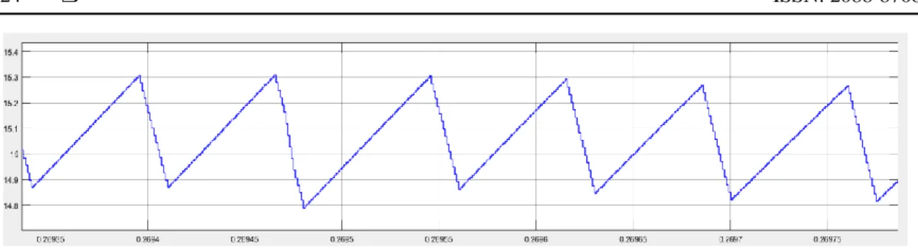
The speed and torque response of DTC based on PID controller is illustrated in Figures 10. The results show that the fulfillment DTC with PID controller is better than the classical DTC when load torque is applied and removed. The torque ripple in the traditional DTC is 1.3 which the difference between the references torque and the maximum or minimum ripple as in Figure 11 while it is reduced to (0.3) when used PID controller as in Figure 12. The system minimizes the overshoot, reduced settling time, minimize torque ripple, Also the starting performance characteristic of the system is improved clearly, speed is regulated but its reduced something when increase in load.
Figure 7. Stator current response
Figure 9. Response of speed and torque in classical DTC
Figure 10. Response of speed and torque in DTC with PID controller
Figure 12. Torque ripple in DTC with PID controller
7. CONCLUSION
In this paper a PID controller was used to get better performance characteristic of DTC for 3-phase IMD. The performance of DTC with PID controller is analysis at deferent load conditions and compared with the classical DTC performance. The system shows that the DTC based on PID controller has better output performance over traditional DTC.
REFERENCES
[1] D. R. D. A. Pandian, "Performance Analysis Of Direct Torque Control Of 3-Phase Induction Motor," Journal of Theoretical and Applied Information Technology, vol. 62, no. 3, pp. 819-824, 2014.
[2] K.-B. L. a. F. Blaabjerg, "Improved Direct Torque Control for Sensorless Matrix Converter Drives with Constant Switching Frequency and Torque Ripple Reduction," International Journal of Control, Automation, and Systems, vol. 4, no. 1, pp. 113-123, 2006.
[3] F. N. Sebti Belkacem, Rachid Abdessemed, "Reduction of torque ripple in DTC for induction motor using input-output feedback linearization," Turk J Elec Eng & Comp Sci, vol. 20, pp. 273-285, 2012.
[4] Mini, R., et al., "Low Speed Estimation of Sensorless DTC Induction Motor Drive Using MRAS with Neuro Fuzzy Adaptive Controller," International Journal of Electrical and Computer Engineering (IJECE), vol. 8, no. 5, pp. 2691, 2018.
[5] Salman, Ghassan Abdullah, Mohammed Hasan Ali, and Ali Najim Abdullah, "Implementation Optimal Location and Sizing of UPFC on Iraqi Power System Grid (132 kV) Using Genetic Algorithm," International Journal of Power Electronics and Drive Systems (IJPEDS), vol. 9, no. 4, pp. 1607-1615, 2018.
[6] A. Jakhar and P. Gaur, "Comparative Study of PI, PID and Fuzzy PI Controller Based Direct Torque Control Induction Motor Drive," Advanced Research in Electrical and Electronic Engineering, vol. 2, pp. 261-265, 2015. [7] Ali, Mohammed Hasan, "Design and Implementation of an Electrical Lift Controlled using PLC." International
Journal of Electrical and Computer Engineering (IJECE)8.4 (2018): 1947.
[8] Dr. Abdulrahim T. Humod and Wiam I. Jabbar, "Direct Torque Control of Induction Motor Based on Particle Swarm Optimization," Journal of Al Rafidain University College, pp. 91-112, 2013.
[9] Kumar, DKiran, and GTulasi Ram Das, "Simulation and Analysis of Modified DTC of PMSM," International Journal of Electrical and Computer Engineering (IJECE), vol. 8, no. 5, pp. 2895, 2018.
[10] Ali Mohammed H., "Mathematical Driving Model of Three Phase, Two Level Inverter by (Method of Interconnected Subsystem)," Iraqi Journal for Electrical And Electronic Engineering, vol. 13, no. 1, pp. 73-82, 2017.
[11] T. K. Dr. T. Govindaraj, "Direct Flux and Torque Control of Three Phase Induction Motor using PI and Fuzzy Logic Controller," International Journal Of Innovative Research In Electrical, Electronics, Instrumentation And Control Engineering, vol. 2, pp. 922-927, 2014.
[12] H. S. Hameed, "Torque Ripple Reduction Based Direct Torque Control for Induction Motor Drives," Master, University Of Baghdad, Iraq, 2014.
[13] R. Anju and M. Sathiskumar, "Direct Torque Control Algorithm for Induction Motor Using Hybrid Fuzzy-PI and Anti-Windup PI Controller with DC Current Sensors," International Journal of Engineering Research and Applications, vol. 4, pp. 58-63, 2014.
[14] Turki Y. Abdalla, Haroution Antranik Hairik, and A. M. Dakhil, "Direct Torque Control System for a Three Phase Induction Motor With Fuzzy Logic Based Speed Controller," Iraq J. Electrical and Electronic Engineering, vol. 6, pp. 131-138, 2010.
[15] B. K. M. Shelby Mathew, "Direct Torque Control of Induction Motor Using Fuzzy Logic Controller," International Journal of Advanced Research in Electrical, Electronics and Instrumentation Engineering, vol. 2, pp. 386-394, 2013.
[16] B. V. Krishna, "Design and Comparison of Vector and Direct Torque Control of 3-Phase Induction Motor Drive," Middle-East Journal of Scientific Research, vol. 20, pp. 586-597, 2014.
[17] Hachicha, M. R., M. Ghariani, and R. Neji. "Induction machine DTC optimization using artificial intelligence for EV's applications." Eighth International Multi-Conference on Systems, Signals & Devices. IEEE, 2011.
[18] Zegai, M. L., et al. "Direct torque control of Induction Motor based on artificial neural networks speed control using MRAS and neural PID controller." 2015 IEEE Electrical Power and Energy Conference (EPEC). IEEE, 2015.
[19] Kazmierkowski, Marian P. "Control strategies for PWM rectifier/inverter-fed induction motors." ISIE'2000. Proceedings of the 2000 IEEE International Symposium on Industrial Electronics (Cat. No. 00TH8543). Vol. 1. IEEE, 2000.
[20] Drif, M’hamed, and Antonio J. Marques Cardoso. "Stator fault diagnostics in squirrel cage three-phase induction motor drives using the instantaneous active and reactive power signature analyses." IEEE Transactions on Industrial Informatics, 10.2, pp.1348-1360, 2014.
[21] Ahmed, Yasser, and Ayman Hoballah. "Adaptive filter-FLC integration for torque ripples minimization in PMSM using PSO." work 3 (2019): 4.
[22] Abdelghani, Draoui, and Allaoua Boumediene. "Independent Control Of Two Induction Motors Fed By The Nine-Switch Inverter For Use In Ev Applications." Journal of Engineering Science and Technology, 14.5, pp: 2991-3006, 2019.
[23] Ali, Mohammed Hasan, and Qasim Al Azze. "Design and implementation a security system for bank using voice recognition." International Journal of Power Electronics and Drive Systems, v10.i4, pp2126-2129, 2019.
[24] Ali, Mohammed H. "Speed Control of (Sedm) Adopting Chopper Converter And Pi Controller." Diyala Journal Of Engineering Sciences, 8.4, pp: 355-364, 2015.
[25] Zegai, M. L., et al. "Direct torque control of Induction Motor based on artificial neural networks speed control using MRAS and neural PID controller." 2015 IEEE Electrical Power and Energy Conference (EPEC). IEEE, 2015.
BIOGRAPHIES OF AUTHORS
Ali Najim Abdullah was born in Diyala, Iraq, in 1981, received his B.Sc. from University Diyala / Iraq in 2003, M. Sc. from University of Belgorod , Russia ,2013 .He is currently assistant lecturer at the Department of Electrical Power Engineering, College of Engineering, University of Diyala Iraq. Professional Strength and Skills: His current research interests are power system modeling, power quality, power stability, power reliability, renewable energy, electrical machine. He has 10 years experience in practice of Electrical engineering. He is teaching several basic subjects of the Electrical Engineering, University of Diyala Iraq. He has 2 published papers.
Mohammed Hasan Ali was born in Diyala, Iraq, in 1980, received his B.Sc. from University Diyala / Iraq in 2006, M. Sc. from University of Belgorod , Russia ,2013 .He is currently assistant lecturer at the Department of Electrical Power Engineering, College of Engineering, University of Diyala Iraq. Professional Strength and Skills: His current research interests are power system modeling, power quality, renewable energy and power electronics. He has 10 years experience in practice of Electrical engineering. He is teaching several basic subjects of the Electrical Engineering, University of Diyala Iraq. He has 4 published papers.