CONFCNTLR: A VIDEOCONFERENCE CONTROLLER
A thesis submitted to the faculty of San Francisco State University
in partial fulfillment of the requirement for the
degree
Master of Science in
Computer Science
by
Marcia Ann Perry San Francisco, California
Copyright by Marcia Ann Perry
CERTIFICATION OF APPROVAL
I certify that I have readConfcntlr: A Videoconference Controller by Marcia Ann Perry, and that in my opinion this work meets the criteria for approving a thesis submitted in partial fulfillment of the requirements for the degree: Master of Science in Computer Science at San Francisco State University.
___________________________________________ William Tsun-Yuk Hsu
Associate Professor of Computer Science
___________________________________________ C. S. James Wong
Associate Professor of Computer Science
____________________________________________ Deborah A. Agarwal
CONFCNTLR: A VIDEOCONFERENCE CONTROLLER
Marcia Ann Perry
San Francisco State University 1997
Multicast over the Internet has inspired research into building virtual laboratories and developing multimedia conference tools. The Spectro-Microscopy
Collaboratory, under development at Lawrence Berkeley National Laboratory and the University of Wisconsin, Milwaukee, is a project aimed at making virtual laboratories a reality. Confcntlr was developed for use in this collaboratory as a conference controller to enhance the usability of the videoconference tools. It allows local and remote control of the audio and video and provides an integrated interface to the media tools. Confcntlr has changed the paradigm of
videoconferencing so that users do not have to be present at the transmitting site. By presenting a unified interface, it facilitates the management of multiple tools running concurrently. This thesis describes the design, development, and implementation ofconfcntlr, and discusses recent work in videoconference tools, control, and coordination.
ACKNOWLEDGMENTS
I would like to thank my advisor Dr. Deb Agarwal for her guidance and for having provided me with the opportunity to design and develop this thesis. I would also like to thank my thesis committee members, Dr. Bill Hsu and Dr. James Wong, for their support and instruction. Much appreciation also goes to my fellow students and co-workers at LBNL who are always willing to share information, especially John Taylor who patiently answered my Frame questions.
This work is supported by the Director, Office of Energy Research, Office of Com-putation and Technology Research, Mathematical, Information, and Computa-tional Sciences Division, of the United States Department of Energy under Contract No. DE-AC03-76SF00098 with the University of California.
TABLE OF CONTENTS
List of Figures . . . viii
List of Appendices . . . x
1 Introduction . . . 1
1.1 The Spectro-Microscopy Collaboratory . . . 2
1.2 The Conference Controller . . . 4
1.3 Thesis Organization . . . 5
2 Background . . . 6
2.1 Multicast Backbone (MBone) . . . 6
2.2 Media Tools . . . 7
2.3 Conference Management Tools . . . 13
2.4 Summary . . . 20 3 Software Architecture. . . 21 3.1 Requirements . . . 21 3.1.1 Design Requirements . . . 21 3.1.2 Functional Requirements . . . 23 3.2 System Overview . . . 25 4 Implementation. . . 28
4.1 The Control Unit. . . 29
4.2 The Network Unit . . . 31
4.3 The Encryption Unit . . . 32
4.4 The Graphical User Interface. . . 33
5 Algorithms . . . 39
5.1 Data Structures . . . 39
5.2 Sequences of Operations . . . 40
5.2.1 Local Operations . . . 41
5.2.2 Network Unit Algorithms . . . 43
5.2.3 Initiating Remote Operations . . . 45
5.2.4 Responding to Messages Received from the Network Component 47 5.3 Error Handling . . . 53
6 Summary and Future Work . . . 55 References . . . 58 Appendices . . . 61
LIST OF FIGURES
1 The primaryvic user interface panel with an expanded view of the incoming video
feed shown below it . . . 11
2Vic’s menu window reached by pressing "menu" on the vic panel . . . 11
3 Thevat user interface . . . 12
4 Thewb user interface. . . 13
5Sdr’s main window shows the currently advertised sessions . . . 16
6Sdr’s session information window . . . 16
7Sdr’s session creation window . . . 17
8 The Conference Bus . . . 23
9Confcntlr’s Components. . . 25
10 Communication Channels . . . 27
11Confcntlr’s main window . . . 33
12 The Conference window . . . 35
13 Main window with pulldown menus . . . 35
14 Menu for setting remotevic and vat controls . . . 36
15 Advanced Audio WIndow . . . 36
16 The Security Window . . . 37
17 Prompt Panel to Approve a Remote Request for Setting Changes . . . 38
18 Warning Panel for Notification of Changes Made by a Remote Host . . . 38
20 Warning Panel to Display Denial of Action. . . 38
21 Initialization . . . 41
22 Termination . . . 41
23 Startingvic and vat on Local Host . . . 42
24 Stoppingvic and vat on Local Host . . . 42
25 Changing Localvic or vat Settings. . . 43
26 Sending a TCP Message . . . 44
27 Receiving a TCP Message. . . 45
28 Requesting a Remote Operation . . . 46
29 Processing a TCP Request . . . 48
30 Changing Parameter Values . . . 49
31 Startingvic or vat in Response to Remote Request . . . 50
32 Changingvic or vat Settings in Response to Remote Request . . . 51
LIST OF APPENDICES
A Further Information . . . 61 B Confcntlr: User Manual . . . 62
Chapter 1 Introduction
Recent advances in network and computer technology have made it possible for users at remote locations to actively participate in scientific research without trav-eling to laboratories where the experiments are being conducted. It is possible to receive data and observe analysis results, and to control the instruments and col-laborate with other remote scientists within a distributed electronic environment. In 1993, the National Research Council stated that
“The fusion of computers and electronic communications has the potential to dramatically enhance the output and productivity of US researchers. A major step toward realizing that potential can come from combining the interests of the scientific community at large with those of the computer science and engineering community to create integrated, tool-oriented computing and communications systems to support scientific collaboration. Such systems can be called ‘collab-oratories’ ”[4].
Building virtual laboratories has become an active field in which emerging tech-nology, work in distributed computing, and data management have been recently applied to provide location-independent access to data, equipment, and collabo-rators.
1.1 The Spectro-Microscopy Collaboratory
The United States Department of Energy has funded a series of four projects to develop, implement, and integrate the technology required to make virtual labora-tories a reality. These projects are called the “Distributed Collaboratory Experi-ment EnvironExperi-ments Program” (DCEE)[2].
One DCEE project is the Spectro-Microscopy Collaboratory, which is under development at Lawrence Berkeley National Laboratory (LBNL) and the University of Wisconsin, Milwaukee. This collaboratory provides researchers from large and geographically distributed centers remote access to a synchrotron-radiation beamline and to the analytical tools at LBNL’s Advanced Light Source (ALS). The various components of the collaboratory allow remote equipment control, environ-ment monitoring, data collection, a shared view of the data and results, and com-munication between participants[1].
Videoconference tools are used to facilitate person-to-person interaction. The videoconference tools utilized by the Spectro-Microscopy project researchers are: vic for transmitting and receiving video images, vat for transmitting and receiving audio signals,wb (whiteboard) for shared drawing and sending and receiving slides, andsdr (session directory) for identifying and launching confer-ences that are being broadcast. These tools have been built upon the IP multicast
capability, which provides efficient multi-point communication. Multicasting has been implemented by building a virtual network on top of the Internet, which is called the Multicast Backbone, or MBone[16]. (See Appendix A for pointers to MBone tools and information.)
Thevic and vat tools allow researchers at the ALS to start the video and audio on the local computer and transmit the images and sound to either a unicast or multicast address. Users at a remote site can receive the video and audio by startingvic and vat on their local hosts. The sdr tool lists the conferences that are broadcasting and allows users to select the conference and startvic and vat locally fromsdr windows.
While these tools represent a large technological advancement, they can be enhanced further. Each one of them has a separate interface and none can be controlled remotely. Users cannot usesdr to change the local vic or vat parame-ters; they must manipulate controls on thevic or vat windows. Also, none of these tools allows a user at one host to launch or stop the videoconference tools on another host or to change the parameters on a remote site once a tool has been started. For example, if the computer at the ALS is not runningvic or vat, users at the University of Wisconsin, Milwaukee cannot start a video or audio tool on the ALS computer withvic, vat, or sdr. If the computer at the ALS is transmitting video at a certain bandwidth and a frame rate, users in Milwaukee cannot change these
values nor can they turn remote video transmission on or off.
Inability to adjust video or audio parameters remotely can be frustrating to the remote participant. Furthermore, because the video feed can take up a large amount of bandwidth and potentially saturate the network, there are times when the transmission rate and bandwidth should be reduced (e.g., when there are no remote users watching the video). This currently requires a human operator at the computer that is transmitting the video, which can be a burden to the
researchers who are conducting the experiments. The computer technology and tools that allow remote participation in an experiment should not take a researcher away from the experiment itself; nor should they require that researchers spend a great deal of time managing the conference session.
1.2 The Conference Controller
Confcntlr was developed for use in the Spectro-Microscopy Collaboratory project as a conference controller. It is a new MBone tool that works in conjunction with other videoconference tools to enhance the usability of video and audio. It allows local and remote control of the audio and video tools and provides a single inter-face tovic and vat. Users at one site can start a video or audio session at another site and can specify the parameter values. Oncevic or vat is running, remote users can change the video or audio settings without stopping and restarting the
tools and they can turn video transmission on or off without stopping and restart-ingvic.
By providing remote control of video and audio tools,confcntlr has
changed the current paradigm of videoconferencing so that users do not have to be present at each feed. By presenting a unified interface for these tools, it facili-tates the management of multiple tools running concurrently. (See Appendix B for theconfcntlr user manual.)
1.3 Thesis Organization
This document describes the design, development, and implementation of con-fcntlr, a conference controller which aims to further the collaboratory effort by enhancing the usability of existing videoconference tools. The next chapter will survey the multicast network infrastructure and discuss recent work in videocon-ferencing. Chapter 3 will present the conference controller’s architecture. Chap-ter 4 will discuss the design and implementation ofconfcntlr. The algorithms used byconfcntlr will be described in chapter 5. Chapter 6 will summarize the thesis, identify further needs, and suggest additional features forconfcntlr.
Chapter 2 Background
Recent research in the development of multicast-based multimedia conferencing tools for the public domain has led to the development of media tools, conference management tools, and conference control protocols. Since most of the tools were built upon the MBone, the chapter begins with a description of IP multicast and the MBone.
2.1 Multicast Backbone (MBone)
Unicasting provides point-to-point communication in which one host is specified as the destination for network packets. Broadcasting allows transmission to multi-ple destinations simultaneously and therefore has the potential to scale well to large numbers of receivers. With broadcasting, all hosts on a network receive copies of the packet being transmitted. With multicasting, IP datagrams are sent to all hosts listening on a multicast group address. Each group has a unique IP multicast (class D) address; a multicast group consists of hosts that want to get packets with the specified class D address. These groups are dynamic; hosts may join or leave a multicast group at any time[6].
The multicast backbone, or MBone, implements IP multicast. It is a new technology which has not yet been fully deployed to all routers and hosts on the Internet. When a host wants to join a multicast group, it issues a request to do so and then receives packets transmitted to the specified multicast address. A host can transmit packets to a multicast address without knowing which sites will receive them; the receivers have the responsibility of joining the group. To limit the scope of a multicast packet, a time-to-live (TTL) value is specified. The TTL is decremented each time that it is received by a router. When the TTL is less than the link threshold, the packet is not forwarded. By convention, a TTL between 1 and 16 would be used to keep packets within a single network while a TTL of 127 would be specified for global traffic.
2.2 Media Tools
Videoconferencing tools for sending and receiving media streams may be inde-pendent, standalone applications, or they may be components that work together within a multimedia conferencing system. Media include video, audio, and shared workspaces on which conference participants may write or draw. This section will discussNet Video from Xerox PARC, IVS and Rendez-Vous from INRIA, and vic, vat, and wb from Lawrence Berkeley National Laboratory. All of these tools are based on a replicated architecture and all use the Real Time Protocol (RTP) on top of IP Multicast. RTP contains a data delivery protocol to handle the actual
media transmission and a control protocol to manage information such as sender identification and to provide time-stamping, packet sequencing, and receiver feed-back.
Net Video, ornv, provides video-only conferencing and is one of the earli-est MBone tools. It allows users to send and receive slow frame rate video as point-to-point or multicast streams[25]. nv uses a software-based codec and a custom coding scheme that has low computational complexity. Its graphical user interface allows users to select a video stream from among those displayed, set parameters, and view conference information. Video parameters include grabber controls and transmit and receive options (e.g., size and color).
The INRIA Videoconferencing System (IVS) was developed at the same time asnv. It transmits real-time audio and video over the MBone[25]. The audio codecs are PCM and ADPCM. The video codec is a software implementation of the H.261 standard which provides a video compression algorithm that can achieve a very high compression rate. Thus, while its simpler encoding givesnv better run-time performance,IVS uses less bandwidth. However, the H.261 stan-dard was originally developed for the Integrated Services Digital Network (ISDN), which can provide better quality of service (QoS) than the Internet because of its guaranteed bandwidth. To maintain good QoS while minimizing bandwidth,IVS implemented schemes to adapt the H.261 video compression algorithm to the
Internet environment. These schemes included packetization, error control, and output rate control. The packetization scheme formats RTP and H.261 header information and uses macroblock fragmentation of the payload. Since UDP pack-ets may be lost or arrive out of sequence, an error control scheme was imple-mented to mitigate against packet loss. In order to control network congestion, IVS adapts its video output rate to network conditions. IVS allows users to call up and talk to someone on the Internet. It also displays a list of participants and the media they are using[24].
Rendez-Vous is under construction as the successor to IVS[15]. It pro-vides video and audio within one application. It is described as an integrated scheduler for media flow management and processing, which optimizes resources to maximize the quality rendered to the user. The audio component is an integra-tion of theFreePhone audio tool, recently developed at INRIA. The basic features ofRendez-Vous include: support of RTP over multicast or unicast IP, the H.261 video standard, high-quality PCMU, ADPCM, UADPCM with HiFi support and low-bandwidth GSM and LPC audio encoding. Advanced features include: flexibility for inserting new protocols and coding schemes, multi-level audio redundancy for bad network links, dynamic media rate control (i.e., adaptation to match the avail-able bandwidth), support for layered coding and transmission of media flows, and multiresolution wavelet and discrete cosine transform (DCT) codecs.
Vic, vat, and wb are separate but interoperable applications. Vic is a visual tool;vat is an audio tool; and wb is a shared whiteboard. Vic and vat extend the work ofnv and IVS with a more flexible system architecture that supports hard-ware-based codecs and a variety of compression algorithms, a model for confer-ence coordination, and an extensible user interface. These tools implement a software decoder for each supported compression format so that, if a sender uses a hardware codec, all receivers can decode the stream. Vic and vat support a variety of formats. Vic’s encoding scheme gives better compression performance compared tonv and better runtime performance and packet-loss tolerance com-pared toIVS. Vat has mechanisms to dynamically adapt itself to network delays, supports several methods of avoiding feedback or echo from the microphone to the speaker, and supports different modes of interaction (e.g., lecture mode in which the speaker’s microphone is continuously open and “push-to-talk” in which users push a button to open their microphone and release it when they are fin-ished)[17]. More recently,vat has supported the use of a hardware echo cancel-ler for hands-free operation.
Interprocess communication for application interoperability is achieved by local multicasting through a communication channel termed the “Conference Bus.” Each application that is connected to this channel can broadcast messages and all processes that are connected to the channel get a copy of the message. Each conference has its own conference bus to coordinate the media within that
ses-sion. For example,vic can focus on the current speaker using cues from vat and floor control can be supported (e.g., a directive can be broadcast to let receivers ignore the media from all participants except the one who holds the floor). There is also a global conference bus for interaction among different sessions, such as for access to shared video and audio devices.
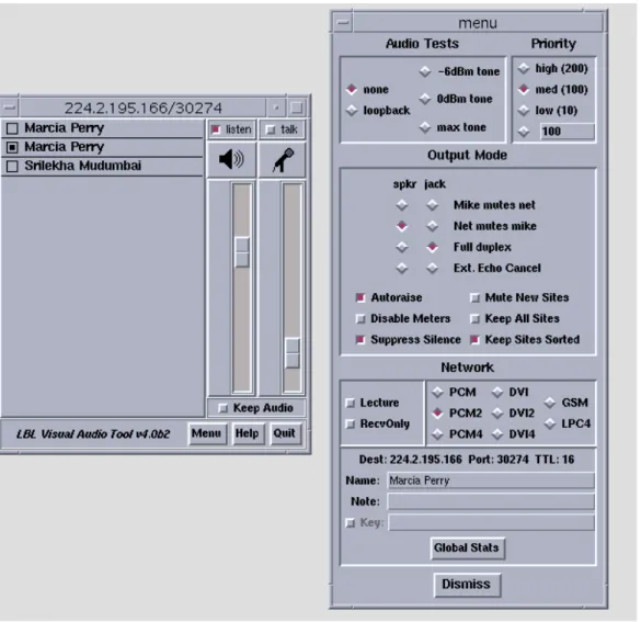
The controls forvic and vat allow users to set a wide variety of parameters and change them while the programs are running. Both tools keep track of and display a list of participants and allow users to mute and unmute media sources. Users can augment or change the behavior of these tools by writing their own scripts which are evaluated byvic or vat. Figures 1 and 2 show vic’s user inter-face and Figure 3 showsvat’s user interface.
Figure 1: The primaryvic user interface panel with an expanded view of the incoming video feed shown below it.
Figure 2: Vic’s menu window reached by pressing “menu” on thevic panel. The list of members is shown to the right of thevic menu.
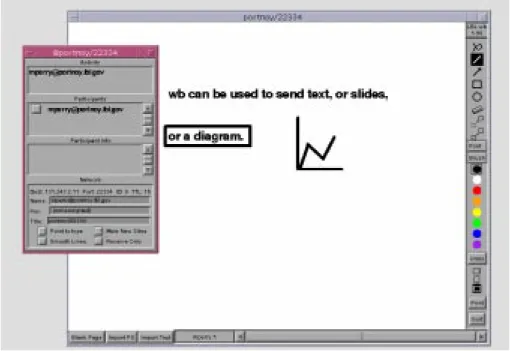
wb provides a shared whiteboard on which users may draw or write. When a change is made, updates are made to all participants’ workspaces simulta-neously. Since it can import PostScript files,wb can be used to send slides. Fig-ure 4 showswb’s user interface.
2.3 Conference Management Tools
Conference control has included: session creation, announcement, and control; application control; floor control; and resource management. Session creation encompasses allocating addresses and specifying the information necessary to start the conference with the correct initial state (e.g., session identifer and media tools). Session announcement includes directory services to advertise availability and methods of rendezvous. Session control entails managing participation (e.g., who is sending and receiving what media), authentication (e.g., session identifica-tion, encryption keys), and presentation of coordinated user interfaces. Applica-tion control refers to the ability to start and stop media applicaApplica-tions and change
Figure 4: Thewb user interface. The user information window is shown on the left.
media-specific features locally or remotely. Floor control is the management of media access (e.g., who can send audio or video and which streams can be muted by receivers). Resource management includes conference scheduling (i.e., booking systems) and the allocation and management of bandwidth to avoid network congestion. At lower levels, conference control has included connection control and protocol conversion to support different networks (e.g., ISDN and packet networks)[9,13,20].
While some of the media tools discussed above provide some control func-tions, external management tools have been developed as separate applications or components of conferencing systems. The control tools presented below are: the Multimedia Conference Control program (MMCC) from USC/ISI, the Session Directory Tool (sdr) from MICE/ESPRIT, the Integrated Session Controller (ISC) from FOKUS, andTelePort from LUTCHI.
MMCC was developed as a prototype session orchestration tool for point-to-point and multipoint multmedia conferences[21]. Its main functions are to sup-ply session creation and maintenance services and to manage the media. The media tools are separate applications and includevat, nv, and wb. Built on a dis-tributed, peer-to-peer model,MMCC is meant to execute continuously on a work-station residing at each conference site. The media tools may be executed on a separate machine. Conference participation is by invitation only.
To establish a conference, a user enters the required information and invites other users to participate. MMCC allows a caller to explicitly invite others to join a conference and alerts them to accept or decline. When a user creates a session,MMCC assigns a conference address and identifier, spawns the selected media tools with the specified configuration (e.g., device, bandwidth, and coding algorithm) if it can be met, and alerts the callee to accept or decline the invitation. An “autopilot” facility allows callees to automatically accept or decline invitations. When a participant leaves the conference,MMCC tears down the media. MMCC allows remote control of data rate and hardware devices (e.g., cameras, codecs, and monitors). Although the actual data flow is left to the individual media compo-nents,MMCC passes session and control information to them and to other
MMCCs. This information includes lists of participants and timing information for inter-media synchronization. MMCCs use the Connection Control Protocol (CCP) to communicate with each other. Multicasting of control information is via sequen-tial unicast rather than via the MBone.
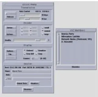
Thesdr session directory is an MBone conference scheduling and booking system. It has been described as an “Electronic TV Listings Guide” [5]. Events are either broadcasts or interactive meetings, using a variety of media tools. Sdr supports public and private sessions and performs the following basic tasks: lis-tening for announcements and listing sessions; starting the relevant media tools; creating sessions; and allowing users to make private “phone calls” to other users.
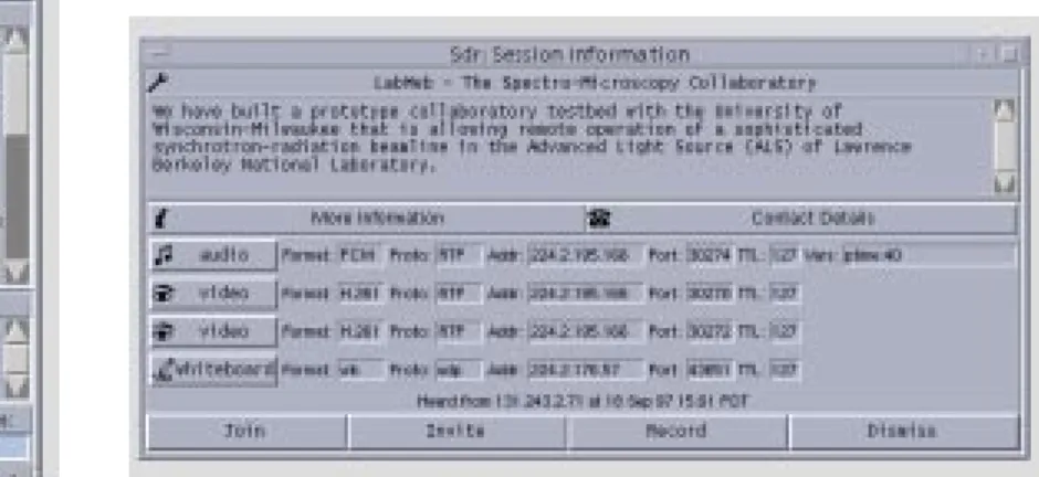
It utilizes the following protocols: Conference Control Channel Protocol (CCCP), Session Description Protocol (SDP), Session Announcement Protocol (SAP), and Session Initiation Protocol (SIP). Figure 5 shows the main window. When a user clicks on a session title, a “Session Information Window” (shown in Figure 6) appears to allow users to join a session, invite others to do so, or record media.
As shown in Figure 6, session information is displayed along with the tools used in the conference. A user can start the tools singly or join the conference by starting all of them. Additionally, users can access a web page by clicking on the “More Information” button and they can view the names and locations of the ses-sion creators by clicking on the “Contact Details” button. To set up a conference, the creator must specify the information necessary to advertise and start the con-ference. The standard tools supported are: vat and rat for audio, vic and nv for video,wb for whiteboard, and nt for text. New media and new tools for existing
Figure 5: Sdr’s main window shows the currently advertised sessions.
Figure 6: Sdr’s session information window. The tools and multicast addressing information is listed along with a description of the session.
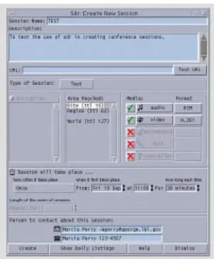
media may be defined. A session creation window is shown in Figure 7.
ISC is one component of the Multimedia Internet Terminal (MInT) confer-encing system, which is currently under development[22]. ISC is a central confer-ence controller that interoperates with the other components of the system,
namely, media agents and auxiliary controllers. The media agents include the Network Video Terminal (NeViT) and vic for video and the Network Voice Terminal (NeVoT) for audio. The media agents provide unicast and multicast sessions over RTP/UDP/IP. Auxiliary controllers include the Session Invitation Terminal (SInT), a reservation agent, and a floor controller. ISC provides an integrated graphical user interface for the media and conference controls. WhileNeVoT has its own
Figure 7: Sdr’s session creation window. This window is used to create a conference session.
graphical user interface,NeViT does not; it is controlled through ISC.
ISC allows users to establish conferences and invite other users to partici-pate. It also manages conference parameters and displays the participants and their status (which media they are using and whether they are sending or receiv-ing). To create a conference, users specify the media and their settings (e.g., encoding, maximum bandwidth, maximum frame rate, and quality) and the net-work configuration (e.g., UDP or ATM and parameters such as burst length and peak bandwidth). If the requested configuration is available,ISC starts the media on the local host. ISC also supports bandwidth reservation using the reservation agent as an interface to an RSVP daemon. To invite another user to participate in the conference, the caller enters the email address of the callee. ISC forwards this address toSInT which, through the use of daemons, verifies what host the callee is logged onto and sends the invitation request. The remoteISC receives the request, displays a panel used to accept or reject the invitation, starts the media if the request is accepted, and sends a reply. During the conference, the participants’ list can be used to enable or disable receiving media streams. Addi-tionally,NeViT adapts its sending behavior to the congestion state of the network (i.e., it reduces its sending rate when large losses are reported in the received RTCP packets). ISC is used to turn this algorithm on or off and to set its parame-ters. ISC also displays network traffic statistics such as bandwidth, loss, and jitter values.
Communication betweenISCs is via TCP connections. Communication between components on the same host is via local multicast, if it is supported. If local multicast is not supported,MInT uses a “message replicator,” which is a sep-arate process that forwards control messages to controllers and media agents, using the “pattern-matching multicast communication protocol” (PMM). The goal in designingMInT was to obtain the benefits of both tightly-coupled and loosely-coupled architectures. Since the media agents are separate applications, they can be replaced, updated, and reused. ISC’s integrated user interface makes these tools more manageable and the use of local multicast (or PMM) allows the interoperability of the independent controllers and media agents. However, once a media tool has been started, its settings cannot be changed by a remote site.
TelePort is under construction as a research vehicle for the study of issues in the design of multimedia communication systems interfaces[3]. It interacts with vic, vat, and wb, and can be launched from sdr. TelePort provides users with awareness of what other participants in a group are doing--how busy they are, whether they can be interrupted, who they are talking to, and whether they are available for collaboration. It uses the metaphor of the office door to represent a user’s availability. Users set options such as “working hard” and choose icons to indicate whether their doors are open or closed. The main window displays these options as well as the video and audio capability (e.g., “no speaker, no micro-phone,” “no speaker, have micromicro-phone,” “have speaker, no micromicro-phone,” or “have
speaker, have microphone”). The availability state of remote users and a list of participants are also displayed. Control packets are multicast according to an experimental “Group Awareness Protocol” (GAP). Group members usually belong to a work or project group and explicitly join aTelePort session. TelePort emphasizes the use of social, rather than technological, methods of multimedia session control. It builds upon current work in the development of “Media
Spaces.” It is described as a proof of concept prototype of the effectiveness of the principles underlying the “Social Computer”--a system that allows users to apply their knowledge of social protocols in deciding what they should do rather than embedding social rules within the system.
2.4 Summary
Work in the multimedia conferencing area has been largely concerned with the development of media tools and their infrastructures. Attention has been given to improving the quality of service while minimizing bandwidth. It is only recently that research has been devoted to conference control. Some efforts have emphasized conference system architecture while others have emphasized usability or func-tionality (e.g., session creation, announcement, and invitation). However, remote control capabilities have been limited to starting tools on remote sites, not to changing remote settings while a tool is executing. Users must operate the tools at both the sending and receiving sites and thus divide their time between confer-ence participation and manipulation of videoconferconfer-ence tools.
Chapter 3
Software Architecture
Confcntlr was built to control videoconference tools locally and remotely through a unified interface. This chapter will define the conference controller’s require-ments more specifically and explain its basic components. The implementation will be explained in terms of the interoperability of these components in Chapter 4.
3.1 Requirements
The following sections delineate the features that must be included in the design of the conference controller and the actions that it must perform.
3.1.1 Design Requirements
The major design requirements are a graphical user interface and a communica-tion system. The communicacommunica-tion system permits data exchange between con-fcntlrs running on remote hosts and between confcntlr and videoconference tools running on the same host. The graphical interface has to be intuitive to users and unobtrusive. It is meant to replace the independent media interfaces or be used in conjunction with them. Because the conference controller allows remote control of other tools, security is also an important feature
Since remote control requires data exchange between conference control-lers on different hosts, a reliable message-based mechanism is required for send-ing and receivsend-ing requests and replies. In addition to communicatsend-ing with other hosts and processes, users must be able to manipulate controls in the graphical user interface at all times. Therefore, confcntlr has to be nonblocking. Once a message has been sent, the user should not be prevented from further operation becauseconfcntlr is waiting for a reply. To ensure that all sites could be consid-ered equal, a peer-to-peer rather than client-server paradigm is required.
Vic, vat, and wb use the local multicast “conference bus” for coordination of a videoconference session[17]. A design requirement for the conference control-ler is to utilize the conference bus for communication with the other videoconfer-ence tools. Because the hardware can support multiple video cards, one host must be able to execute more than one video tool. It is also possible to execute multiple audio tools. Therefore, the conference bus is shown in Figure 8 as a communication channel between any number of video and audio tools.
3.1.2 Functional Requirements
The major functional requirements were to allow users to view and change param-eters, carry out operations for local and remote control of video and audio, provide security features, and display the system status. The parameters include the con-ference name and address, time-to-live, and values specific to each medium (e.g., video bandwidth, frame rate, quality, device, compression format, and transmis-sion).
The actions that must be supported are the following:
• start a specific video or audio tool on the local or remote host with user-selected parameter values
• start all video and audio tools on the local or a remote host with user-selected parameter values
• stop a video or audio tool running on the local or remote host • obtain a remote host’s settings and find out which videoconference
tools are running on that host
• change parameter values for a video or audio tool that is already exe-cuting
• turn video transmission off and on while the video tool is running
video 1
confcntlr video n audio n
Figure 8: The Conference Bus. Confcntlr can exhange information with any number of video and audio tools running on the same host.
Since communication between conference controllers is over the public Internet, confidentiality and integrity of data must be preserved. Thus, the confer-ence controller must support encryption. Messages sent to a remote host can be encrypted and messages received can then be decrypted, using an agreed upon key that users can change. Also, users must be able to turn off encryption if they wish. The conference controller has to detect whether data read from the network has been encrypted or not.
To provide uninterrupted media and protect computer resources, the con-ference controller should be able to restrict remote access to authorized users and hosts. Local users should be able to restrict actions such as having the video or audio turned on and off. Also, since exceedingly high bandwidths or frame rates could saturate the network, users should be able to monitor or limit changes in these values.
The required security features are:
• encryption/decryption of data exchanged between conference control-lers at remote sites
• detection of whether data is or is not encrypted • allowing users to change the encryption key • allowing users to turn off encryption
• capability of restricting control of the conference controller to authorized users and hosts
• capability for users to grant or deny permission for another host to change values or perform an operation (unconditionally or on a per change-request basis)
3.2 System Overview
The conference controller was built to work withvic and vat. The conference con-troller has four components that work together to provide the necessary function-ality. These components are:
• graphical user interface • control unit
• network unit • encryption unit
The graphical user interface (GUI) receives user input and displays output. The control unit contains the functions to set values or carry out actions. Although not directly visible to the user, this is perhaps the locus of the main work of the conference controller. Transparent to the user and at a lower layer is the network unit that provides the mechanism for host-to-host and interprocess communica-tion. It is invoked whenever messages need to be exchanged and, in turn, invokes the encryption unit when these messages are transmitted or received over the network. Figure 9 shows the relationships of the four components.
GUI Control Unit
Encryption Unit Network Unit
Figure 9: Confcntlr’s Components. The arrows indicate the data flow.
All actions go through the control unit. When a user manipulates a control in the graphical user interface, values are set or actions are carried out by func-tions in the control unit. If a message is to be sent to a remote host or to a video-conference tool on the same host, the control unit invokes the network unit. The network unit invokes the encryption unit only when messages are sent to or received from a remote host. When a message is received by the network unit (from either a remote host or from the video or audio tools on the same host), the control unit processes the message and the graphical user interface displays the output.
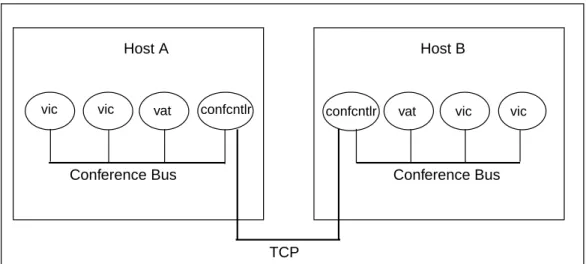
The network component is responsible for establishing connections and transmitting and receiving data over the communication channels to support host-to-host and interprocess message exchange. Figure 10 depicts these communi-cation channels.
Data transfer between conference controllers running on different hosts is via the Transmission Control Protocol (TCP), which provides reliable, ordered, uni-cast delivery[6]. The communication required to satisfy a request may be half-duplex or full-half-duplex, depending upon whether a reply or acknowledgment is required. Data transfer between applications running on the same host is via the multicast conference bus local to the host.
Host A
vic vic vat confcntlr confcntlr vat vic vic
Host B
Conference Bus Conference Bus
TCP
Figure 10: Communication Channels. A TCP connection is for peer-to-peer communication while the conference bus is used for interprocess communication within a single host.
Chapter 4 Implementation
Confcntlr was implemented on SUN workstations running the Solaris 2.5.1 operat-ing system and ported to Silicon Graphics workstations runnoperat-ing the Irix 6.2 oper-ating system. It was written to controlvic and vat. Although one confcntlr controls one conference session, multipleconfcntlrs can be run to allow users to partici-pate in multiple conferences. To obtain directory and booking services,confcntlr can be launched fromsdr. Confcntlr is a single-threaded application that does all of its processing within an event loop. Host-to-host and interprocess communica-tion were implemented with the socket interface[23].
The Data Encryption Standard (DES) was used for encryption[8]. The net-work and encryption units and part of the control unit were written in the C pro-gramming language. The graphical user interface and most of the control unit were written in Tcl/Tk[18,26]. Tk is well-suited for creating windows for the X Win-dow System, which is employed by Solaris. Tcl provides an interface to C that makes it possible to write applications in a combination of C and Tcl/Tk. It also provides an event loop and a simple way to do nonblocking, nonsequential I/O.
The implementation of each functional component will be discussed in the following sections. The algorithms, presented in Chapter 5, will describe the way
confcntlr works and how these components operate together.
4.1 The Control Unit
The control unit carries out local operations invoked by the GUI or network unit. These operations include starting and stoppingvic and vat or changing the set-tings for a tool that is executing on the local host. The control unit also formats requests for and replies to operations on remote hosts.
When the GUI invokes the control unit to start (or stop) a tool on the local host, the control unit spawns (or terminates) a process for the tool selected. When a user changes a localvic or vat setting and the tool is running, the control unit formats a message and invokes the network unit to transmit the message via the conference bus. When a user initiates a remote operation, the control unit for-mats a message and invokes the network component to establish a connection and send the request.
If a message arrives fromvic or vat on the conference bus, the control unit updates its settings and invokes the GUI to display the new values or status. For example, if the user clicks the “quit” button in thevic or vat window, a message is broadcast on the conference bus. Confcntlr’s network unit forwards the message to the control unit, which determines which tool sent the message, updates the
required values, and then invokes the GUI to display the new status. If a remote host requested starting the tool, that host is sent a termination notice. If the user changes a setting in thevic or vat window (e.g., video transmission or audio input or output gain), a message is also broadcast to the conference bus and again confcntlr’s network unit forwards the message to the control unit which updates the appropriate parameter and invokes the GUI to updateconfcntlr’s display.
When the network unit receives a request, reply, or notification from anotherconfcntlr running on a remote machine, it forwards the message to the control unit for identification and processing. Upon receiving a request, the con-trol unit identifies the action and invokes security functions (e.g., checking the authorization level and prompt options). It invokes the GUI to display prompt pan-els when the user wants to manually set permissions. The requested action is carried out only if permission is granted. The control unit formats a reply for every request that it processes and forwards the reply to the network unit for transmis-sion.
Upon receiving a reply or notification, the control unit updates values and calls the GUI to update the display (e.g., remote settings were sent, a request was denied, or a remote tool was terminated by its local user). If a request is denied, the control unit invokes the GUI to create and display a warning panel.
4.2 The Network Unit
The network unit is responsible for opening and closing communication channels and sending and receiving data. The sockets for sending and receiving mes-sages over the conference bus and the socket on which the conference controller listens for TCP connection requests are opened once and remain open for the duration of the program. A separate TCP connection is opened and closed for each remote operation. To allow the conference controller to function as a sender or receiver at all times without blocking, a file handler is created when a socket is opened. The file handler arranges for the appropriate procedure to be invoked whenever data arrives on the socket.
The network component is responsible for host-to-host and interprocess communication. There are two host-to-host communication schemes.
1. Host A sends a request to host B. Host A does not wait for a reply unless it is obtaining a remote host’s settings. Host B receives the request, processes it, and sends a reply.
2. Host A notifies host B that some event took place (e.g., host A terminated a process). Host B receives and processes the notification but does not send a reply.
Interprocess communication works as follows. Messages sent to other applications running on the same host are broadcast via the conference bus. Each application that is connected to this channel receives a copy of the message and, if an application recognizes the message type, it processes the message
locally and may also forward that message to a conference controller at a remote site. Acknowledgments and replies are not sent. Events that are broadcast are the following:
• vic or vat was terminated and wants to notify the conference controller • the conference controller wants to dynamically change a setting onvic
orvat
• vic or vat changed its setting and wants to notify the conference control-ler
4.3 The Encryption Unit
Because encryption routines are not currently allowed to be exported from the United States andconfcntlr was to be placed on the World Wide Web, two ver-sions of the conference controller were built, one that supports encryption and one that does not. We’ll refer to these in this section asconfcntlr-crypt and con-fcntlr, respectively.
The encryption component ofconfcntlr-crypt invokes functions from the SSLeay library to encrypt plain text and decrypt ciphertext, using the key provided by the caller (the network unit). The encryption unit ofconfcntlr returns immedi-ately if the encryption and decryption functions are called. With the exception of the encryption component, both versions of the conference controller have the same code. The different versions are built by compiling and linking with the appropriate encryption components.
A conference controller that supports encryption is able to control a confer-ence controller that does not, but the reverse does not hold. The encryption unit tells the network unit whether or not the conference controller supports encryp-tion. When the control unit processes a message, it queries the network unit which, in turn, queries the encryption unit to determine if encryption is supported. The encryption section in the security window of the user interface is not built if encryption is not supported.
4.4 The Graphical User Interface
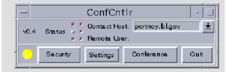
The graphical user interface (GUI) passes the input received from a local user to the control unit and displays the output passed to it from the control unit. Since minimizing screen real estate was important,confcntlr presents a small main dow that displays the system status and controls for basic operations. Popup win-dows can be opened for specific categories of functions (e.g., local or remote settings, security features, general conference control). For user convenience, menus with predefined values are utilized along with entry fields to allow users to type their own values. The main window is shown below in Figure 11.
In the upper portion of the main window are the version number, buttons for displaying the tools running, and host addresses. The two columns of buttons labeled “Status” indicate whichvics and vats are running locally and remotely (the left column in Figure 11 indicates that onevic and one vat are running on the local machine while the right column indicates that bothvics and one vat are running on the remote host). The Contact Host displays the address of the machine with whichconfcntlr is communicating and the Remote User displays the user who most recently performed remote control. In the lower portion of the main window are buttons to open the security, settings, and conference windows and to quit the program. The image in the lower left corner displays the remote control access level. On color monitors, the image displays red, yellow, and green, to correspond to the authorization levels “allow no one,” “allow authorized users”, and “allow any-one,” respectively.
The conference window, opened when the “Conference” button is clicked, is shown in Figure 12. It displays the contact host, conference name, time-to-live (TTL), conference address and port for each video and audio tool, and buttons for starting and stopping local and remote tools or getting a remote host’s settings. This window (and all subwindows) can be iconified with the “Dismiss” button. Val-ues can be reverted to their defaults via the “Reset to Defaults” button.
The local and remote menus are opened via the “Settings” button’s pull-down menu, shown in Figure 13. They contain the parameters for the video and audio running on the local and remote hosts, respectively. The remote menu is shown in Figure 14 (the local menu is the same).
Figure 12: The Conference Window
Clicking on buttons labeled “Port...” or with an arrow open popup menus with predefined values. Figure 14 shows two of these menus. Figure 15 shows the “advanced audio window” that is opened by clicking on the “AdvAud” button.
Figure 14: Menu for setting remotevic and vat controls
The security window shown in Figure 16 displays the authorization levels, options for prompt and warning panels, an editable authorization list, and an edit-able encryption key. The prompt and warning panels may be used for setting per-missions for remote control or notifying the user that an action has taken place. In Figure 16, options are chosen to “prompt to approve setting changes” and “turn on warnings.” With the latter option, the local user is notified whenever a change is made by a remote user and she or he has not been prompted to manually
approve the change. Examples of panels displayed for each of these options are shown in Figures 17 and 18. When a remote request is refused, a warning panel like those in Figures 19 and 20 may be displayed.
Figure 20: Warning Panel to Display Denial of Action
Figure 17: Prompt Panel to Approve a Remote Request for Setting Changes
Figure 18: Warning Panel for Notification of Changes Made by a Remote Host
Chapter 5 Algorithms
This chapter describes the primary data structures of the software components, explains the steps taken byconfcntlr to carry out the actions invoked, and dis-cusses how errors are handled.
5.1 Data Structures
The control unit’s primary data structures are C character arrays to store requests and replies and Tcl arrays to store the parameter values. Each local and remote vic and vat is allocated its own array with its parameters as indices. These param-eters include bandwidth, pid, format, etc. For convenience, the algorithms will refer to these arrays as “localtool” and “remotetool” to denote the tool being acted upon (e.g., localvic1 or remotevic2).
The setting and displaying of parameter values are achieved as follows. Controls in the graphical user interface are associated with Tcl variables. When a widget’s value is changed, its associated variable is automatically updated and, if the variable is assigned a value anywhere in the program, the widget displays the new value. Thus, the GUI and the control unit share variables associated with widgets.
The network component utilizes application-specific data structures for storing messages. Since messages broadcast over the conference bus are exchanged betweenconfcntlr and vic or vat, confcntlr defines the same fields for conference bus message structures asvic and vat, namely, a header and a char-acter array for the data. The header includes integers to represent the message type, a “magic” constant, and the process identification (pid) of the sender. The character array will be referred to as the “text” field.
For messages transmitted over TCP connections, the network unit main-tains a data structure with two fields: a “length” field and a character array to store the actual data. The character array will be referred to as the “text” field. The encryption unit maintains this same type of data structure.
5.2 Sequences of Operations
When the conference controller is launched, it initializes its components and enters the event loop. Upon termination, it checks for settings changes and per-forms cleanup before it exits. The pseudocode for initialization and termination are shown in Figures 21 and 22, respectively.
The following sections describe the sequences of operations for performing the actions invoked within the event loop. They will be presented in the following order: the algorithms used by the control unit for local operations, the algorithms used by the network unit for sending and receiving messages over the conference bus and TCP connections, the algorithms used by the control unit for initiating remote operations, and the algorithms used by the control unit for processing messages received from the network unit.
5.2.1 Local Operations
Launch of the videoconference tools on the local host can be initiated by the GUI or network unit. Upon receipt of a request to start all tools, each video and audio tool is executed in sequence. Whenvic or vat is started, confcntlr writes a Tcl script for that tool to set parameter values (which overridevic or vat default val-ues), define the types of conference bus messagesvic or vat must recognize,
Init_App()
establish signal handler; initialize Tcl/Tk;
implement Tcl/Tk and C interface; set default values;
open TCP socket used for listening for connection requests;
open multicast conference bus sockets for sending/receiving data;
create main window; invoke Tcl/Tk event loop;
Terminate_App() if (setting changed) display “save panel”; write defaults file; endif
close main TCP socket; close conference bus sockets; terminate each local vic/vat that is running;
remove files created during execution;
exit;
define procedures to invoke upon receipt of these messages, and define any other procedures to augment functionality. Confcntlr spawns vic and vat as child pro-cesses with command line arguments for options such as the conference address and name of the user-written Tcl script. Each unique process identifier (pid) is stored in the array corresponding to the tool started. The algorithm used by the control unit for starting one or more local tools (vic and vat) is given in Figure 23.
To stop one or more tools on the local host, the control unit retrieves the process identifier for each tool that is being terminated and terminates that pro-cess. If the tool has stopped at the request of a host other than the one that requested its execution, a notification is sent to the host that started the tool (referred to as the “launcher”). This algorithm is given in Figure 24.
Start_Local_Tool(tools) for each tool in tools do write Tcl script for tool;
format command line arguments; execute tool;
localtool(pid) := tool pid; endfor
Figure 23: Startingvic and vat on Local Host
Stop_Local_Tool(tools) for each tool in tools do kill localtool(pid); localtool(pid) := -1;
if (launcher != local_host) then send notification to launcher; endif
endfor
The algorithm for changing parameter values forvic or vat running locally can be invoked by the GUI or the network unit. When values are changed in the local menu and the tool is running, the control unit formats a message tovic or vat and invokes the network unit to broadcast the message. When the target process receives the message, it implements the change. The algorithm for dynamically changing localvic and vat settings is given in Figure 25.
5.2.2 Network Unit Algorithms
To send a message over the conference bus, the network unit calls CB_Send, which completes the fields of its message structure and broadcasts the message. When the network unit is called to receive a conference bus message, it calls CB_Receive. CB_Receive checks the process identifier (pid) in the header. If the pid does not matchconfcntlr’s process identifer, the message may be from vic or vat; the data is forwarded to the control unit for further processing.
The algorithm used by the network component to send a TCP message assumes that its caller (the control unit) provides the socket descriptor, encryption
Change_Local_Settings(parameters, tool) if (localtool(pid) > 0) then value := localtool(parameter); format message; CB_Send(message); endif
key, and message. Users can turn off encryption by entering an empty key. As discussed in Section 4.3, there is one version of the conference controller that can perform encryption and another version that cannot. Both versions have an encryption component which contains a function (referred to as “crypt_on”) that returns a value to indicate whether encryption is supported. If encryption is sup-ported, the network unit calls the encryption unit to perform the encryption and then writes the message to the TCP socket. The pseudocode for sending a TCP message is given in Figure 26.
The algorithm for receiving a TCP message assumes that its caller (the control unit) provides the socket descriptor, the encryption key, and buffers for returning the message along with values indicating whether encryption is sup-ported and whether the message was encrypted. The network unit reads the length and then the message. If the length is a negative integer, the encryption unit is called to decrypt the message. The network unit returns the plaintext mes-sage and values that indicate whether encryption is supported and whether the message was encrypted. If a conference controller that supports encryption
TCP_Send(socket, data, key) message.text := data;
message.length := length of data; if (crypt_on() && key) then
encrypt(message.data, key);
message.length := message.length * -1; endif
write message to TCP socket;
receives an unencrypted message, it returns an error code. The pseudocode for receiving a TCP message is given in Figure 27.
5.2.3 Initiating Remote Operations
Remote operations include starting and stoppingvic and vat on a remote
machine, changing parameter values of a tool running on a remote machine, and obtaining another host’s settings. The network unit waits for a reply only if the request is to get another host’s settings.
When users request a remote operation, the control unit formats a request message and calls the network unit to open a TCP connection with the contact host and send the message.
TCP_Receive(socket, key, data, crypt_support, encrypted) read message.length from socket;
if (message.length < 0) then message.length := message.length *-1; encrypted := true; else encrypted := false; endif crypt_support := crypt_on();
if (!crypt_support &&encrypted) then data := “was encrypted”; return;
endif
read from socket message.length bytes into message.text; if (crypt_support && encrypted) then
decrypt(message.text, key); endif
data := message.text; return number of bytes read;
The message types are:
• “start_tool” to startvic or vat (e.g., start_vic1) • “start_all” to start bothvics and vat
• “stop_tool” to stopvic or vat (e.g., stop_vic1) • “stop_all” to stop all tools running
• “cb_tool” to change the settings on a tool that is running (e.g.,cb_vic1) • “get_params” to obtain a host’s settings.
The format of each message is: “message_type user@host arguments,” where the arguments vary with respect to the message type. For example, the arguments for a “start_tool” message list the parameter values of vic or vat. The arguments for “stop_tool” and “stop_all” requests are the pids of the tools being stopped. The arguments for a “cb_tool” request are a list of the parameters to change and a list of their new values. There are no arguments for “get_params” requests. (A “get_params” request is automatically sent to the specified contact host when confcntlr is started and when the user changes the contact host.) The algorithm for requesting a remote operation is given in Figure 28.
Remote_Operation(operation) format request for operation; if (operation != get_settings) then
open nonblocking TCP socket; create file handler for socket; else
open blocking TCP socket; endif
TCP_Send(socket, request, key); if (operation == get_settings) then
/* wait for a reply */ endif
5.2.4 Responding to Messages Received from the Network Component
To read messages, the control unit invokes the network unit from either a file han-dler or from a routine that is performing sequential I/O. Each message is pro-cessed by a routine that is defined for its message type. In describing how the conference controller handles the messages it receives, we will assume that, if the message arrived on the conference bus, CB_Receive has been called.
A conference bus notification is in the format: “action pid arguments.” For example, the message “changeParam 1234 transmit 0” means that process number 1234 turned off transmission and the message “adios 1234” means that process number 1234 was terminated. The control unit identifies the action and, if it is recognized, it searches the arrays for local tools until it finds a matching pid and makes the necessary updates.
To respond to a TCP request message, the control unit identifies the send-ing host, checks whether the message is encrypted, and determines if encryption is supported. If encryption is supported and the message is encrypted, additional security checks are performed; otherwise, an error message is sent. If remote control access is being granted, the next step is to parse the action and the argu-ments from the request and call a subroutine to carry out the requested action. When the subroutine returns, a reply is sent and the TCP connection is closed.
This algorithm, Process_TCP_Request, is shown in Figure 29, .
The subroutines called are: Do_Start for “start_tool” or “start_all” requests, Do_Stop for “stop_tool” requests, To_Cb for “cb_tool” requests, and
Send_Settings for “params” requests. Do_Start and To_Cb use the same algo-rithm to change settings, Do_Changes, given in Figure 30.
Process_TCP_Request(message, crypt_support, encrypted) if (message == “was encrypted” && !crypt_support) then
TCP_Send(“encryption not supported”); close TCP connection;
return; endif
check authorization;
if (requestor is not authorized || remote control is disabled) then TCP_Send(“operation not allowed”);
close TCP connection; return;
endif
identify the action;
if (crypt_support && !encrypted) then TCP_Send(“not authorized”); close TCP connection; return;
endif
if ((action == “start_tool”) || (action == “start_all”)) then identify the tool and requested values;
reply := Do_Start(tool, requested_values); else if (action == “stop_tool”) then
identify the tool; reply := Do_Stop(tool); else if (action == “cb_tool”) then
identify the tool, parameters, and values; reply := To_Cb(tool, parameters, values); else if (action == “params”) then
reply := Send_Settings(); else
/* invalid request */ reply := error message; endif
TCP_Send(reply); close TCP connection;
The arguments to Do_Changes() are the tool, a list of parameters to change, and a list of requested values. The first step is to check the given lists to make sure that the parameters are supported and that the requested values are different from the current values. Next, default permissions are assigned to each parameter to be changed. If a prompt option is set for a given type of parameter, the GUI is invoked to display a dialog box so that the user can override the default permission. Changes are made if the permission is “allow”. Do_Changes returns a list of parameters not changed and a list of parameters that were changed according to their default permissions along with their original values. The
Do_Changes(tool, parameters, new_values) foreach parameter in parameters do
if (parameter is supported && new_value of parameter != localtool(parameter)) then add parameter and new_value to a list of changes;
if (prompt option == “on” for this type of parameter) then add parameter and its new_value to lists for prompt panel; endif
endif endfor
if (there are items for a prompt panel) then display prompt panel;
endif
foreach parameter in list of changes do if (permit(parameter) == “allow” ) then
if (parameter is not on prompt panel list) then
add parameter and its current value of parameter to lists for warning panel; endif
localtool(parameter) := new_value of parameter; else
add parameter to “rejects” list; endif
endfor
return “rejects” list and warning panel list;
“rejected” parameters are sent in the reply and the lists of changes made are used for warning panels.
The Do_Start subroutine, shown in FIgure 31, obtains the permission value for a “start” action and returns a “permission denied” message if the action is not allowed. Otherwise, it continues by calling Do_Changes to set parameters to their requested values and Start_Local_Tool to executevic and/or vat. The routine invokes the GUI to display necessary panels and updated values.
Do_Start(tool, new_values)
if ((“prompt to approve all actions”==true) && (“prompt to approve start/stop”==true)) then display prompt panel;
else
permit(start) := default permission value; endif
if (permit(start) == “not allow”) then return “permission denied”; endif
general_parameters := “version conference_name ttl”;
Do_Changes(general_parameters, values for general_parameters); foreach tool do
parameters := parameters applicable to tool;
Do_Changes(parameters, new_values for parameters); concatenate prompt panel lists returned by Do_Changes; concatenate warning panel lists returned by Do_Changes; endfor
Start_Local_Tool(tool);
if ((list for warning panel != null) && (“turn on warnings”==true)) then display warning panel;
endif
reply := pid(s) of tool(s) started;
concatenate “rejects” list(s) and append to reply;
update display; /* configure labels on local ‘start’ buttons */; return reply;
To change the settings onvic or vat, Do_Changes is called with a parame-ter list and requested values. If the change is made, the control unit formats a conference bus message and invokes the network unit to send it. The GUI dis-plays a warning panel if the change was made without a prompt panel. The pseudcode is given in Figure 32, To_Cb.
To stopvic or vat, the Do_Stop subroutine calls Stop_Local_Tool, if the action is permitted. It invokes the GUI when necessary to display a prompt panel and update the status, and it returns a reply to Process_TCP_Request.
The Send_Settings subroutine lists the values of all the parameters on the responding host as well as what tools are running and what video and audio devices it has. It returns a concatenated list. Figure 33 shows the pseudocode.
To_Cb(tool, parameters, values)
reply := Do_Changes(parameters, values);
/* if Do_Changes returns a null “rejects” list, the requested changes were approved*/ if (“rejects” == null) then
if ((“changed_parameters” list is not empty) && (“turn on warnings”==true) then display warning panel;
endif
Change_Local_Settings(parameters, tool); endif
update display; return reply;
Since a reply to a request may not be received immediately after the request was sent, the replies include the name of the sending host and the action that was requested. The format of the reply depends upon its type. For example, replies to “start” or “stop” requests include the pid(s) of the tools(s) being started or stopped as well as a list of the tools running. The replies to “start” and “cb_tool” requests list any parameters whose changes were rejected. The replies to
“get_params” requests include the values of all parameters, a list of tools running, and lists of the video and audio devices on the sending host. If an action failed, the reply contains an error code.
When the control unit receives a reply, it identifies the sender and action, and then parses the remaining fields of the message. If the requested action was not carried out (e.g., permission was denied or there was an error), the GUI dis-plays a warning panel. If the contact host is the same as the sender, the control unit updates the parameters of the remote tool with the values specified in the reply and the GUI updates the display. If the contact host is not the same as the
Send_Settings()
list general parameter values; /* version number, conference name, ttl */ foreach tool do
list parameter values; endfor
list tools running on local host;
list video and audio devices on local host; return concatenated list;