Load Frequency Control for Hydropower Plants
using PID Controller
Ali Thaeer Hammid
1, 2, Mojgan Hojabri
1, Mohd Herwan Bin Sulaiman
1, Ahmed N. Abdalla
3, Atheer A. Kadhim
2 1Faculty of Electrical & Electronics Engineering, University Malaysia Pahang, 26600 Pekan, Malaysia.2Department of Computer Engineering Techniques, Al Yarmouk University College, 32001 Ba’aqubah, Diyala, Iraq. 3Faculty of Engineering Technology, University Malaysia Pahang, 26350 Gambang, Malaysia.
Abstract—Many development republics began to get rid of
conventional energy and towards to use renewable energy like hydropower system, solar cells and wind turbines as soon as possible. Load Frequency Control (LFC) problem is coming to be the main topics for mentioning schemes due to not corresponding between main power system inputs such as change load demand and change in speed turbine settings. This paper illustrates a self-tuning control of hydropower system that suggested and confirmed under Automatic Generation Control (AGC) in power scheme. The suggested power system involves one single area. The suggested self-tuning control system is employed in performing the automatic generation control for load frequency control request and compared it with conventional control structure. The power system dynamic modeling has regularly built in several essential parameters which have a significant influence According to frequency limitation. The main problem with all controllers is an exaggerated reaction to minor errors, producing the system to oscillate. The output response results for hydropower system obviously proved the benefit of using maximum load demand by tuning PID controller. Whereas, tuning PID controller has got properly more rapid output response and minimal overshoot.
Index Terms—Hydro Power Generation; Automatic Generation Control (AGC); Tuning PID Controller and Load Frequency Control (LFC).
I. INTRODUCTION
Hydropower golden age was in the first half of the 20th century before oil control of the force of the dominant in the provision of energy [1]. Several growth republics gradually began to get rid of traditional energy originals that built on oil, coal and the usual gas, owing to oil price increment, fossil fuel cost, thermal pollution and crisis of worldwide energy and renewable hydro plant facilitates over conventional [2].
According to size increment, complication and varying construction of unified power systems, Load Frequency Control (LFC) problem comes to be the main topics for mentioning schemes. Load variation request in a control area is unexpected. Moreover, some load variation request reasons are not corresponding between power production and consumption.
Load frequency control target is to sustain frequency and power exchanges oscillations for getting wanted possibility importance in all control areas of a power network. While execute mentioned aims, numerous LFC algorithms were
being suggested corresponding load demands and the power output of the LFC production under adjustable process conditions.
Recently request of a decentralized control plan to the LFC difficult has established varied approval since its role in removing several of the difficulties like control, independence law on disturbance, by peculiar area output evidence to all area controllers such as Proportional Integral Derivative (PID) controller that related to further centralized or multilevel control plans. To provide a different modern method that obtains the as Proportional Integral (PI) or PID parameter controller that built on an optimization technology by the constant-M circles in Nichols chart that let system to make tuning for PID controller by using Matlab/Simulink and adjust its parameters according to change system dependability.
II. AUTOMATIC GENERATION CONTROL (AGC) Power system operation has certainly been considered under situations of stable load. Anyhow, both of active and reactive power will be unstable and they frequent variation with increasing or dropping trend [3].
Automatic Generation Control (AGC) is an actual significant topic in the power system process for providing adequate and dependable electric power. At unified power scheme, for the load request differs casually, the area frequency and tie-line power exchange diverge too. The load frequency control using single a governor control executes boundary grade to reduce frequency oscillations and tie-line power exchange. Anyhow, LFC is essentially for the difficulty of a sudden not corresponding between the production and active power request.
The controller considered from around process point built in linear model achieved by linearization was deficient because of the non-linear power system landscape. Power system process topic could vary since varying loads throughout the day period. While a minor load trouble in one area of the unified scheme happens, tie-line power exchange and power system frequency oscillations endure to get an extended period, even if the optimized increase item of integrated controllers. When oscillations damp out in express probable period, automatic generation control involved component is employed. Thus the Area Control Error (ACE) was employed for suggested controller response. The ACE is achieved by
deviation of tie-line power stream and the frequency that biased using a partiality influence β illustrated in Equation (1).
ACE = ΔPtie + βΔf (1)
As the active achievement of the AGC structure will clearly rely on the frequency partiality influences value, β, and integral controller increase importance [4].
Typically, AGC is structured in three stages:
Primary control was achieved by the speed governors of the power production parts, which provide automatic act immediately for rapid changing in load or frequency. During this way, system frequency variation is larger than the dead band of the governor velocity and result would adjustment unit power production. Thus, primary controls transients were in the time-scale of seconds.
Secondary control repair frequency to its nominal importance and keeps production, exchange among areas using regulating selected generators productivity. Thus, secondary controls transients were in minutes order.
Tertiary control was an economic dispatch that employed for system, leading carefully as possible, then returned safety stages if required. Usually tertiary control was achieved each 5 minutes [5].
The control system ability and its balance for load-generation and frequency are restrained with the Area Control Error (ACE). The system production units are controlled on the basis of the ACE importance. Utilities were being activated once every 10 minutes at least to get all utility zeros the area control error and to make load-generation is stable and the frequency is equivalent to the nominal. Mentioned process is expensive, needing a feedback control loop structure and power plant components wear and tear from the controller action frequently [6].
III. HYDRO TURBINES AND ITS CONTROL MODULE The power system dynamic modeling has regularly built in several essential parameters which have a significant influence on the frequency through isolated system process next great instabilities. Moreover, the parameters of PID controller must be measured. A structure governor droop has been never precisely for the governing system model because of PID controller's usage. Nevertheless, plenty of parameters are desirable for a system model, including due to small frequency deviation can cause huge load instabilities [7].
At native power schemes, hydro turbine velocity in several different regions might have diverse characteristics for universal subsystem. Principally hydro power, high quantity subsystem contains with the turbine and its governing and generator-load system model.
1 (2) . 1 g Governor modeling T s . 1 (3) 0.5 . 1 w w T s
Hydro turbine modeling
T s
1 (4) . 1 p
Generator and Load modeling
T s 1 (5) p
Droop Characteristic modeling R
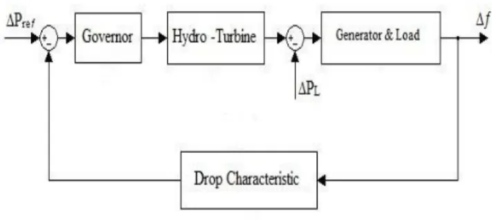
where these suggested system parameters considering: the governor droop (Tg = 0.2) as illustrated in Equation (2), the constant of water starting time value (Tw = 4.0) as illustrated in Equation (3), the constant inertia value (TP = 0.6) as illustrated in Equation (4), and constant the damp value (RP = 20 (1/RP = 0.05)) as illustrated in Equation (5). Typically the whole system model showed in Fig.1. Where Δƒ is frequency variation, ΔPL is the change in load demand and ΔPref is a
change in the water valve opening.
Figure 1: Hydro turbine, its Governing and Generator-Load system model The turbine governor system controls the water inlet into a turbine, which automatically turn the generator rotation for producing electricity. In order to keep a required generated frequency of 50Hz, the rotation speed has to be kept constant. The turbine governor obtains information from the existing velocity of the turbine and then regulates water stream to maintain the turbine speed at the accurate level [8]. In this control structure, the pipes scheme is fixed by servo valve controlled using a servo motor. Actually coding ability of servo schemes performs it additional adjustable for different control requests. Most commonly employed situation control by using a servo motor because of regulation of armature voltage charge the field constantly [9].
Essentially hydro turbine transfer function is not smallest stage since water inertia. Thus, every changing stage of valve situation produces an undesirable response on production turbine power. According to speed governor nominal values, turbine and machine parameter involves into a steady system where the stable regular constant of the speed governor must be 20%. Anyhow, these measurements are typically around 5% and this performs an improvement is undesirable. Thus, the system response, succeeding a slight load adjustment will be unbalanced. A transient droop compensator is properly proposed to be involved in the speed governor to resolve mentioned difficulties [10].
A single model is more commonly employed for the power scheme load dynamics. Inter-machine fluctuations among diverse positions owing to system instabilities are disregarded rely on dependable model. The rules of accurate are sufficient for minor isolated system by robust networks. The load is commonly supposed to be dispersed through the network that regard as a typical case and it is right confirming the loads
actively from the system loads at model frequency response [7].
IV. FREQUENCY CONTROL
Input of steam to turbo-generators or input of water to a hydro-generators should be controlled the corresponding of active power request continuously. Whereas deficit in engine velocity will diverge with the resulting frequency variation that might be unwanted extremely (maximum allowed in power frequency variation is ± 0.5 Hz) [11, 12].
The Frequency is a fundamental typical to the network and accepts frequency changes limited of Hertz. Large hydropower plants applied in the dams also have governors which control the water flow that enters to the turbine, whereas employing governors for the small hydropower plants is an expensive. If generation is more than total load demand, frequency increases. Else if the total load demand is greater than the generation, island network frequency decreases [13].
Since variations in the feeder of the connected network effect on hydro power plant’s production voltage and the frequency, thus control frequency loop has been planned to confirm the stability of the production frequency. Therefore, frequency control needs several processes of mechanical and electrical subsystems. Usage of the PI controller almost products positive existing indication relies on the adjustable production frequency [14].
In general, Load Frequency Control (LFC) is regarded as an essential portion for Automatic Generation Control (AGC) and is an actual sign power schemes process. It is important machinery in electric power schemes, which stabilities produced power in all control area request to sustain the output frequency and the output power production among area values. Power system contains of the numerous unified control area. In general load frequency controller employs the generators' velocity and governor systems to regulate the opening of steam/water valve opening which regulate the quantity of steam/water fluid into the engine. Therefore, they exactly control the mechanical shaft power for generators. Typically, the load frequency controller input is the Area Control Error (ACE) that is an arrangement for unified frequency fluctuation of clear power exchange error value. All control areas are needed to lead its ACE to zero competently for saving respectable priority and never make the load on further control areas [10].
V. CONTROLLER TYPES AND LIMITATIONS
For confirmation the power scheme is unsteady if the load variation as a product the frequency varies. Nevertheless, the mentioned problem leads the system output response to be slow and lazy quiet. Built on the concept of a novel intelligent PID controller is manufactured, properly model educations and these fields show that the intelligent PID control could slightly increase the dynamic achievement and the regularity of the hydro-turbine governing scheme if associated with the traditional PID controller [10, 15].
The main problem with an extremely proportional controller is that it will be an exaggerated reaction to minor errors,
producing the system to oscillate. While these oscillations will finally be reduced and then removed, but it is better to avoid them competently. While a Proportional controller can perform a stable state, it is nearly impossible to avoid a continuous error at this state. Typically, the controller should have no error at the stable state. This is wherever the Integral phase comes into play [5].
VI. PID TUNING FOR LFC
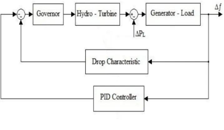
Traditional LFC employs an integral controller. Famously, it is a great integral gain can fail power scheme achievement, producing great fluctuations and instabilities. Accordingly, the integral gain has to make regular stage and then supply compromise among wanted transient regaining and small overshoot in the dynamic output response of the complete system [16]. In fact, the trouble with PID plan and tuning for load frequency control exists for a power system model of second order and usually under-damped. The majority of present PID tuning methods focus on over-damped operations, thus straight request for present PID tuning methods at LFC has been never correct as illustrated in Fig.2 [5].
Figure 2: Hydro turbine unit with PID controller
The equation for a PID controller for a second order system is known as illustrated in Equation (6).
0 = e(t) + e(t) d(t) + a t P I D e t K K K de dt
(6)where ea (t) is the input actuating signal, as controller
parameters, Kp is the proportional gain, TD is the derivative
gain and KI is the integral constant gain. These operations
employed to catch of these constant values are identified as tuning methods. Manual tuning methods normally rely on being capable to check the system response manually and then regulate the PID values until an acceptable response has been found. These values would then be adjusted manually to complete the required performance. These apply the identical methods in the manual methods, automating the operations to decrease the time required and to help increase standardization [8].
VII. SIMULATION RESULTS
There are a much differences for output system response in both cases of change in load demand (ΔPL) = 0.01 p.u. And 0.02 p.u., it depends on changes in water valve opening (ΔPref)
and make the essential effect of frequency. So, the maximum load variation is considered as 0.02 p.u.
Several computing methods are estimated values are also used. Most modern industrial facilities use PID tuning software to confirm reliable results. In this paper, PID tuning is done by Matlab/Simulink to get perfect results for PID controller parameter.
The models have led to different values depending on the water starting time value (Tw) that must be employed. It must
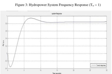
be well-known into these suggested models. While tuning PID controller parameters are not constant as considered for all starting time values. Depending on Fig.2, The system output is displayed in Fig.3, Fig.4, Fig.5 and Fig.6 for Tw = 1.0, 2.0, 3.0
and 4.0 individually. As it's clear, the suggested tuning PID controller could quite have agreeable responses for system output until if water starting time values variations and keep on output system response in limit range for LFC.
Figure 3: Hydropower System Frequency Response (Tw = 1)
Figure 4: Hydropower System Frequency Response (Tw = 2)
Figure 5: Hydropower System Frequency Response (Tw = 3)
Figure 6: Hydropower System Frequency Response (Tw = 4)
PID tuning controller is obviously changing as soon as water starting time (Tw) is changed. The output response
results for hydropower system obviously proved the benefit of using maximum load demand by tuning PID controller. Whereas, tuning PID controller has got properly more rapid output response and minimal overshoot. But if compare tuning PID controller method with intelligence control method, PID tuning controller has a deficiency due to it is thoroughly made and took a lot of time to get stability. Thus, there is necessary need to use an intelligence control method like artificial neural network and fuzzy logic control.
VIII. CONCLUSION
The load-frequency rule features of a one or single control area for hydropower system have been discussed. The suggested tuning PID controller has been displayed to improve the power scheme damping that coming later a stage variation in load and provides an improved achievement over other conventional controllers.
There is no absolutely necessary needing to employ the transient droop compensator and there is an option to use unity feedback system and it is approximately giving same output response. The plan of the tuning PID controller has been generally built on a linearization system modeling requirement theory with various adjustments. The tuning PID controller has properly got well output system response.
APPENDIX
The output response of hydropower system depends on Water starting time value (Tw) and its parameters have been:
For (Tw = 1.0), Rise time = 2.25 Sec, Settling time = 9.8 Sec,
overshoot = 13.3 %
For (Tw = 2.0), Rise time = 2.25 Sec, Settling time = 9.8 Sec,
overshoot = 13.3 %
For (Tw = 3.0), Rise time = 4.51 Sec, Settling time = 25.0 Sec,
overshoot = 9.3 %
For (Tw = 4.0), Rise time = 4.74 Sec, Settling time = 33.6 Sec,
overshoot = 8.12 %
REFERENCES
[1] Mishra, M.K., N. Khare, and A.B. Agrawal, Small hydro power in India: Current status and future perspectives. Renewable and Sustainable Energy Reviews, 2015. 51: p. 101-115.
[2] Duque, E.A., J.D. González, and J.C. Restrepo, Developing Sustainable Infrastructure for Small Hydro Power Plants through Clean Development Mechanisms in Colombia. Procedia Engineering, 2016. 145: p. 224-233.
[3] D P Kothari, I.J.N., Modern Power System Analysis. IIT Delhi, New Delhi, India, 2010. third edition: p. PP. 290-325.
[4] Sheikh, M.R.I. and N. Mondol. Application of self-tuning FPIC to AGC for Load Frequency Control in wind farm interconnected large power system. in Informatics, Electronics & Vision (ICIEV), 2012 International Conference on. 2012.
[5] Alam, M.S., A. Singh, and D. Guha. Optimal solutions of load frequency control problem using oppositional krill herd algorithm. in 2016 IEEE First International Conference on Control, Measurement and Instrumentation (CMI). 2016.
[6] Debbarma, S. and A. Dutta, Utilizing Electric Vehicles for LFC in Restructured Power Systems Using Fractional Order Controller. IEEE Transactions on Smart Grid, 2016. PP(99): p. 1-11.
[7] Gao, L., J. Xia, and Y. Dai. Analysis of power system frequency responses with hydro turbines incorporating load shedding. in 2010 5th IEEE Conference on Industrial Electronics and Applications. 2010. [8] Zhang, G., et al., Research of Hydro-turbine Governor Supplementary
Control Strategy for Islanding AC Grid at Sending Terminal of HVDC System. IEEE Transactions on Energy Conversion, 2016. PP(99): p. 1-1. [9] Pravin, P.S. and J.J. Abdul. Performance evaluation of an isolated small
hydro power plant using conventional controllers. in Circuits, Power and Computing Technologies (ICCPCT), 2013 International Conference on. 2013.
[10] Meng, L. and F. Diao. QFT fractional order controller for non-minimum phase hydro power plant. in Control Conference (CCC), 2012 31st Chinese. 2012.
[11] Vrdoljak, K., et al. Optimal distribution of load-frequency control signal to hydro power plants. in 2010 IEEE International Symposium on Industrial Electronics. 2010.
[12] T, H.A., Applications of Tuning Control Actions for the Efficient Load/frequency Control in Steam Turbine. International Journal of Current Engineering and Technology, 2013. 3(5): p. 1895-1898. [13] Safaei, A., H.M. Roodsari, and H.A. Abyaneh. Optimal load frequency
control of an island small hydropower plant. in Thermal Power Plants (CTPP), 2011 Proceedings of the 3rd Conference on. 2011.
[14] Lefort, R., et al. High Frequency MV/LV transformer modelling for Power Line Communication applications. in Power Line Communications and its Applications (ISPLC), 2014 18th IEEE International Symposium on. 2014.
[15] Ahammad, F.U.A. and S. Mandal. Robust load frequency control in multi-area power system: An LMI approach. in 2016 IEEE First International Conference on Control, Measurement and Instrumentation (CMI). 2016.
[16] Polyakov, A. and L. Hetel, Relay Control Design for Robust Stabilization in a Finite-Time. IEEE Transactions on Automatic Control, 2016. PP(99): p. 1-1.