Politecnico di Torino
Porto Institutional Repository
[Article] Toward dynamic virtualized network services in telecom operator
networks
Original Citation:
Cerrato, Ivano; Palesandro, Alex; Risso, Fulvio; Suñé, Marc; Vercellone, Vinicio; Woesner, Hagen
(2015).
Toward dynamic virtualized network services in telecom operator networks.
In:
COMPUTER
NETWORKS
, vol. 92 n. 2, pp. 380-395. - ISSN 1389-1286
Availability:
This version is available at :
http://porto.polito.it/2629392/
since: March 2016
Publisher:
Elsevier
Published version:
DOI:
10.1016/j.comnet.2015.09.028
Terms of use:
This article is made available under terms and conditions applicable to Open Access Policy Article
("Public - All rights reserved") , as described at
http://porto.polito.it/terms_and_conditions.
html
Porto, the institutional repository of the Politecnico di Torino, is provided by the University Library
and the IT-Services. The aim is to enable open access to all the world. Please
share with us
how
this access benefits you. Your story matters.
Towards Dynamic Virtualized Network Services in Telecom Operator Networks
Ivano Cerratoa, Alex Palesandroa, Fulvio Rissoa,∗, Marc Su˜n´eb, Vinicio Vercellonec, Hagen Woesnerb
aDepartment of Computer and Control Engineering, Politecnico di Torino, Torino, Italy bBerlin Institute for Software Defined Networks GmbH, Berlin, Germany
cTelecom Italia lab, Torino, Italy
Abstract
NFV and SDN are nowadays seen as a solid opportunity by telecom operators to reduce costs while at the same time providing new and better services. Recently, the Unify project proposed a multi-layered architecture that, leveraging different levels of abstraction, can orchestrate and deploy generic network services on the physical infrastructure of the telecom operator. In this paper, we exploit such an architecture to deliver end-to-end generic services in presence of multiple concurring players (e.g. network operator, end-users), leveraging a new simple data model. Particularly, we propose a description-based approach allowing to deploy agile, implementation-independent and high-level network services over a distributed set of resources. The resulting data model can abstract generic services, including both middlebox-based (e.g., firewalls, NATs, etc.) and traditional LAN-based ones (e.g., a bittorrent client). Finally, two distinct prototypes, originated by different design principles, are implemented in order to validate our proposal with the aim of demonstrating the adaptability of our approach to different contexts.
Keywords: NFV, SDN, service graph, forwarding graph, virtual network functions, network orchestration
1. Introduction
The way network services are delivered has dramatically changed in the last few years thanks to the Network Functions Virtualization (NFV) paradigm, which allows network services to experiment the same degree of flexibility and agility already available in the cloud computing world. In fact, NFV proposes to transform the network functions that today run on dedicated appliances (e.g., firewall, WAN accelerator) into a set of soft-ware images that can be consolidated into high-volume stan-dard servers, hence replacing dedicated middleboxes with vir-tual machines implementing those Virvir-tual Network Functions (VNFs). Thanks to their software-based nature, VNFs could be potentially deployed on any node with computing capabili-ties located everywhere in the network, ranging from the home gateway installed in the customer premises till to the data center servers [1, 2].
NFV is mainly seen as a technology targeting network oper-ators, which can exploit the power of the IT virtualization (e.g., cloud and datacenters) to deliver network services with un-precedented agility and efficiency and at the same time achieve a reduction of OPEX and CAPEX. However, also end users (e.g., xDSL customers) can benefit from NFV, as this would enable them to customize the set of services that are active on their Internet connection. But, while NFV currently focuses mostly on middlebox-based applications (e.g., NAT, firewall), end users are probably more oriented to services based on tra-ditional network facilities (e.g., L2 broadcast domains), which receive less consideration in the NFV world.
∗Corresponding author. Email address: [email protected].
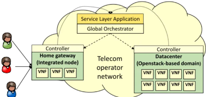
Motivated by the growing interest, e.g., of telecom operators, in extending the functionalities of Customer Premise Equip-ments (CPEs) in order to deliver new and improved services to the users [3] [4] [5] [6], this paper presents a solution that is oriented to delivergenericnetwork services that can be se-lected bymultiple players. Particularly, our proposal enables also thedynamicinstantiation ofper-usernetwork services on the large infrastructure of the telecom operators, possibly start-ing from the home gateway till the data center, as depicted in Figure 1. Our solution enables several players (e.g., telecom operator, end users, etc.) to cooperatively define the network services; moreover, it is general enough to support both tra-ditional middlebox functions as well as tratra-ditional host-based network services. For example, a customer can define its own network service by asking for a transparent firewall and a Bit-torrent client, while the network operator complements those applications by instantiating a DHCP and a NAT service1.
In our solution, the entire network infrastructure is controlled by a service logic that performs the identification of the user that is connecting to the network itself, following the approach proposed in [7]. Upon a successful identification, the proper set of network functions chosen by the user is instantiated in one of the nodes (possibly, even the home gateway) available on the telecom operator network, and the physical infrastructure is configured to deliver the user traffic to the above set of VNFs.
The paper describes the service-oriented layered architecture to achieve those objectives, modeled after the one proposed by 1In this paper we assume that end users are only enabled to select VNFs
trustedby the operator. The case in which they can deployuntrustedVNFs (e.g., implemented by the end users themselves) would in fact open security issues that are beyond the scope of this work.
Home gateway (Integrated node)
VNF VNF VNF
Global Orchestrator Service Layer Application
Telecom operator network Controller VNF VNF VNF VNF VNF VNFDatacenterVNF (Openstack-based domain) Controller VNF VNF VNF VNF VNF VNF VNF VNF
Figure 1: Deployment of virtual network functions on the telecom operator network.
the Unify project [8, 9], and a possible set of data models that are used to describe and instantiate the requested network ser-vices starting from an high-level and user-friendly view of the service. The high-level description is then converted into a set of primitives (e.g., virtual machines, virtual links) that are ac-tually used to instantiate the service on the physical infrastruc-ture. Moreover, it presents two possible implementations of the nodes of the infrastructure layer on which the service is actu-ally deployed. Particularly, we explored two solutions that are based on different technologies, with different requirements in terms of hardware resources. The first is based on the Open-Stack open-source framework and it is more appropriate to be integrated in (existing) cloud environments; the second exploits mostly dedicated software and it is more oriented to the domes-tic/embedded segment (e.g., resource-constrained CPEs).
The remainder of this paper is structured as follows. tion 2 provides an overview of the related works, while Sec-tion 3 introduces an architecture to deploy general network ser-vices across the whole network under the control of the telecom operator (as shown in Figure 1). Section 4 details some for-malisms expressing the service to be deployed, which are then exploited to solve the challenges arising from our use case, as discussed in Section 5. Section 6 details the preliminary implementation of the architecture, which is then validated in Section 7, both in terms of functionalities and performance. Fi-nally, Section 8 concludes the paper and provides some plans for the future.
2. Related work
Three FP7 EU-funded projects focusing on the integration of the NFV and SDN concepts (UNIFY [10], T-NOVA [11] and SECURED [12]) started recently. Particularly, the first one aims at delivering an end-to-end service that can be deployed everywhere in the telecom operator network, starting from the points of presence at the edge of the network, till to the data-center, by exploiting SDN and NFV technologies. Similarly, T-NOVA proposes an equivalent approach that puts more empha-sis on the target of providing a uniform platform for third-party VNF developers, while SECURED aims at offloading personal security applications into a programmable device at the edge of the network. An SDN-based service-oriented architecture has been proposed also in [13, 14], which enables to deliver
middlebox-based services to user devices, leveraging Service Function Chaining and SDN concepts.
From the industry side, the IETF Service Function Chain-ing (SFC) [15] workChain-ing group aims at definChain-ing a model to de-scribe and instantiate network services, which includes an ab-stract set of VNFs, their connections and ordering relations, provided with a set of QoS constraints. Similarly, the Eu-ropean Telecommunications Standards Institute (ETSI) started the Industry Specification Group for NFV [16], which aims at developing the required standards and sharing their experi-ences of NFV development and early implementation. Based on the ETSI proposal, the Open Platform for NFV (OPNFV) project [17] aims at accelerating the evolution of NFV by defin-ing an open source reference platform for Virtual Network Functions.
The problem of CPE virtualization, which represents one of the possible use cases of our architecture, is investigated in sev-eral papers (e.g., [3, 4, 5, 6]); however they have a more limited scope as do not foresee the possibility to instantiate the service across an highly distributed infrastructure and focus on more technological-oriented aspects.
Finally, the OpenStack [18] community is aware of the pos-sibility to use that framework to deliver NFV services as well, as shown by the new requirements targeting of traffic steering and SFC primitives [19, 20]; in fact, we rely on some prelim-inary implementation of those functions [21] in order to build our prototype.
3. General architecture
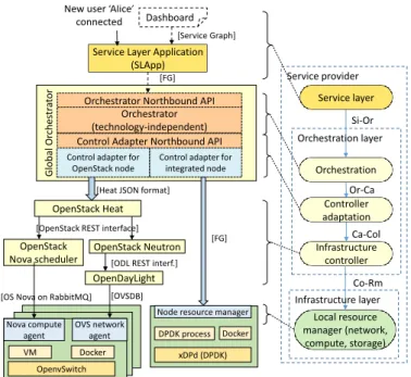
Our reference architecture to deliver network services across the telecom operator network, which follows closely the one proposed by the ETSI NFV working group [16], was defined in the FP7 UNIFY project [8, 9] and it is shown in Figure 2. As evident from the picture, it allows the deployment of network services through three main portions, namely theservice layer, theorchestration layerand theinfrastructure layer.
3.1. Service layer
The service layerrepresents the upper level component of our system and enables different players to define their own net-work services. Although our service layer includes some use-case specific functions such as user identification (detailed in Section 6.1), we introduce here the general concept of a generic service description expressed in an high level formalism called
service graph (Section 4.1), which enables the definition of generic services (expressed independently by each player) and their potential interactions.
The service graph could be provided accompanied with sev-eral non-functional parameters. Particularly, we envision a set ofKey Quality Indicators (KQIs)that specify requirements such as the maximum latency allowed between two VNFs, or the maximum latency that can be introduced by the entire service. We also foresee the definition of a list of high-level policies to be taken into account during the deployment of the service. An example of such policies could be the requirement of deploying the service in a specific country because of legal reasons.
Glo b al O rc h es tr at or
Orchestrator Northbound API Orchestrator (technology-independent) Control Adapter Northbound API
Control adapter for integrated node [FG] Orchestration Controller adaptation Infrastructure controller Local resource manager (network, compute, storage) Service provider Si-Or Or-Ca Ca-Col Co-Rm OpenStack Heat OpenStack Nova scheduler OpenStack Neutron
Node resource manager
xDPd (DPDK) DPDK process Docker
Service Layer Application (SLApp) [Service Graph] Nova compute agent OpenvSwitch VM Docker OVS network agent [FG]
New user ‘Alice’ connected
[Heat JSON format]
[OpenStack REST interface]
[OS Nova on RabbitMQ]
OpenDayLight
[ODL REST interf.] Control adapter for
OpenStack node
Dashboard
Service layer
Orchestration layer
Infrastructure layer
Figure 2: Overall view of the system, including the two implementations of the infrastructure layer.
Given the above inputs, possibly facilitated by some graphi-cal tools that allow different players to select and build the de-sired service, the service layer should be able to translate the service graph specification into an orchestration-oriented for-malism, namely theforwarding graph(Section 4.2). This new representation provides a more precise view of the service to be deployed, both in terms of computing and network resources, namely VNFs and interconnections among them, always con-serving KQIs and policies imposed by the player that defined the service.
As depicted in Figure 2, the service layer includes a compo-nent that implements the service logic, identified with the ser-vice layer application (SLApp) block in the picture. The serser-vice layer could also export an API that enables other components to notify the occurrence of some specific events in the lower layers of the architecture. The SLApp module could react to these events in order to implement the service logic required by the specific use case. An example of such events may be a new user device (e.g., a smartphone) that connects to the network, which could trigger the deployment of a new service graph or an update of an existing one.
Finally, the service northbound interface enables also cloud-like services, as well as it offers to 3rd-party providers (e.g., content-providers) the possibility to deploy services in the op-erator infrastructure, orchestrating resources on demand and be-ing billed for their utilization in a pay-per-use fashion.
3.2. Orchestration layer
The orchestration layer sits below the service layer and it is responsible of two important phases in the deployment of a service.
First, it manipulates the forwarding graph in order to allow its deployment on the infrastructure, adapting the service
def-inition to the infrastructulevel capabilities, which may re-quire the deployment of new VNFs for specific purposes, as well as the consolidation of several VNFs into a single one (Section 4.2). Second, the orchestration layer implements the scheduler that is in charge of deciding where to instantiate the requested service. The scheduling could be based on different classes of parameters:(i)information describing the VNF, such as the CPU and the memory required; (ii) high-level policies and KQIs provided with the forwarding graph; (iii)resources available on the physical infrastructure, such as the presence of a specific hardware accelerator on a certain node, as well as the current load of the nodes themselves.
According to Figure 2, the orchestration layer is composed of three different logical sub-layers. First, the orchestra-tionsub-layer implements the forwarding graph transformation and scheduling in a technology-independent approach, with-out dealing with details related to the particular infrastructure, which is under the responsibility of the infrastructure layer. The next component, called controller adaptation sub-layer, im-plements the technology-dependent logic that is in charge of translating the forwarding graph into the proper set of calls for the northbound API of the differentinfrastructure controllers, which correspond to the bottom part of the orchestration layer. Infrastructure controllers are in charge of applying the above commands to the nodes operating on the physical network; the set of commands needed to actually deploy a service is called
infrastructure graph (Section 4.3) and, being infrastructure-specific, changes according to the physical node/domain that will host the service that is going to be instantiated. The infras-tructure controller should also be able to identify the occurrence of some events in that layer (e.g., unknown traffic arrives at a given node), and to notify it to the upper layers of the archi-tecture. As shown in Figure 2, different nodes/domains require different infrastructure controllers (in fact, each resource has its own controller), which in turn require manycontrol adaptersin the controller adaptation sub-layer.
Having in mind the heterogeneity (e.g., core and edge tech-nologies) and size of the telecom operator network, it is ev-ident how the global orchestrator, which sits on top of many resources, is critical in terms of performance and scalability of the entire system. For this reason, according to the picture, the global orchestrator has syntactically identical northbound and southbound interfaces (in fact, it receives a forwarding graph from the service layer, and it is able to provide a forwarding graph to the next component), which paves the way for a hier-archy of orchestrators in our architecture. This would enable the deployment of a forwarding graph across multiple admin-istrative domains in which the lower level orchestrators expose only some information to the upper level counterparts, which allows the architecture to potentially support a huge number of physical resources in the infrastructure layer. Although such a hierarchical orchestration layer is an important aspect of our architecture, it is out of the scope of this paper and it is not considered in the implementation detailed in Section 6.2.
3.3. Infrastructure layer
The infrastructure layer sits below the orchestration layer and contains all the physical resources that will actually host the deployed service. It includes different nodes (or domains), each one having its own infrastructure controller; the global orchestrator can potentially schedule the forwarding graph on each one of these nodes. Given the heterogeneity of modern networks, we envision the possibility of having multiple nodes implemented with different technologies; in particular, we con-sider two classes of infrastructure resources.
The first class consists in cloud-computing domains such as the OpenStack-based domain in Figure 1, referencing one of most popular cloud management toolkits, each one consist-ing of a cluster of physical machines managed by a sconsist-ingle frastructure controller. The second class of resources is in-stead completely detached by traditional cloud-computing en-vironments, representing nodes such as the future generation of home-gateways hosted in the end users’ homes. One of such a node, calledintegrated node, is shown in the bottom-left part of Figure 1 and consists of a single physical machine that is provided mostly with software written from scratch. Moreover, the infrastructure controller is integrated in the same machine hosting the required service.
The infrastructure layer does not implement any logic (e.g., packet forwarding, packet processing) by itself; in fact, it is completely configurable, and each operation must be defined with the deployment of the proper forwarding graph. This makes our architecture extremely flexible, since it is able to im-plement whatever service and use case defined in the service layer.
4. Data models
This section details the data abstractions that are used to model and then deploy the network services on the physical infrastructure. Our data models are inspired by the NFV ETSI standard [16], which proposes a service model composed of “functional blocks” connected together to flexibly realize the desired service. In order to meet the objectives described in the introduction, we instantiated the ETSI abstract model in multi-ple flavors according to the details needed in the different lay-ers. All those flavors are inspired by the objective of integrating the functional component description of network services and their topology, together with the possibility to model also exist-ing services provided by cloud computexist-ing.
4.1. Service graph
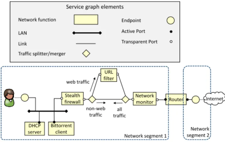
Theservice graph (SG)is a high level representation of the service that includes both aspects related to the infrastructure (e.g., which network functions implement the service, how they are interconnected among each other) and to the configuration of these network functions (e.g., network layer information, policies, etc.). Our SG is defined with the set of basic elements shown in Figure 3 and described in the following of this section. These building blocks were selected among the most common elements that we expect are needed to define network services.
Service graph elements
Network function Link Active Port LAN Endpoint Transparent Port Traffic splitter/merger DHCP server Bittorrent client Stealth firewall URL filter Network monitor Router Network segment 1 Network segment 2 web traffic non-web traffic all traffic Internet
Figure 3: Service graph: basic elements and example.
Thenetwork function(NF) is a functional block that may be later translated into one (or more) VNF images or to a dedicated hardware component. Each network function is associated with a template (Section 4.4) describing the function itself in terms of memory and processing requirements, required processor ar-chitecture (e.g., x86-64), number and type of ports, etc.
Theactive portdefines the attaching point of a NF that needs to be configured with a network-level address (e.g., IPv4), ei-ther dynamic or static. Packets directed to that port are for-warded by the infrastructure based on the link-layer address of the port itself.
The transparent port defines the attaching point of a NF whose associated (virtual) NIC does not require any network-level address. If traffic has to be delivered to that port, the net-work infrastructure has to “guide” packets to it through traffic steering elements, since the natural forwarding of the data based on link-layer addresses does not consider those ports.
The local area network (LAN) represents the (logical) broadcast communication medium. The availability of this primitive facilitates the creation of complex services that in-clude not only transparent VNFs, but also traditional host-based services that are usually designed in terms of LANs and hosts.
The point-to-point link defines the logical wiring among different components and can be used to connect two VNFs to-gether, to connect a port to a LAN, and more.
Thetraffic splitter/mergeris a functional block that allows to split the traffic based on a given set of rules, or to merge the traffic coming from different links. For instance, it is used in Figure 3 to redirect only the outgoing web traffic toward an URL filter, while the rest does not cross that NF.
Finally, theendpointrepresents the external attaching point of the SG. It can be either a logical entity or a specific port (e.g., a physical/virtual NIC, a network tunnel endpoint), active on a given node of the physical infrastructure. An endpoint can be used to attach the SG to the Internet, to an end user device, but also to the endpoint of another service graph, if several of them have to be cascaded in order to create a more complex service. Each endpoint is associated with anidentifierand an optional
ingress matching rule, which are required for the SGs attaching rules to operate (detailed in Section 4.1.1).
Figure 3 provides a SG example with three NFs connected to a LAN, featuring both active (e.g., the DHCP server and the bit-torrent machine, which need to be configured with IP addresses) and transparent ports (the stealth firewall). The outgoing traffic exiting from the stealth firewall is received by a splitter/merge block, which redirects the web traffic to an URL filter and from here to a network monitor, while the non-web traffic travels di-rectly from the stealth firewall to the network monitor. Finally, the entire traffic is sent to a router before exiting from the ser-vice graph. In the opposite direction, the traffic splitter/merger on the right will sendallthe traffic coming from Internet to the stealth firewall, without sending anything to the URL filter as this block needs to operate only on the outbound traffic.
As cited above, the SG also includes aspects related to the configuration of the NFs, which represent important service-layer parameters to be defined together with the service topol-ogy, and that can be used by the control/management plane of the network infrastructure to properly configure the service. In particular, this information includes network aspects such as the IP addresses assigned to the active ports of the VNFs, as well as VNF-specific configurations, such as the filtering rules for a firewall.
The SG can potentially be inspected to assess formal prop-erties on the above configuration parameters; for example, the service may be analyzed to check if the IP addresses assigned to the VNFs active ports are coherent among each others. To fa-cilitate this work, the SG defines thenetwork segment, which is the set of LANs, links and ports that are either directly con-nected or that can be reached through a NF by traversing only its transparent ports. Hence, it corresponds to an extension of the broadcast domain, as in our case data-link frames can traverse also NFs (through their transparent ports), and it can be used to check that all the addresses (assigned to the active ports) of the same network segment belong to the same IP subnetwork. As shown in the picture, a network segment can be extended outside of the SG; for instance, if no L3 device there exists be-tween an end user terminal and the graph endpoint, the network segment also includes the user device.
4.1.1. Cascading service graphs
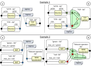
As introduced above, the SG endpoints are associated with some parameters that are used to connect SGs together ( cascad-ing graphs). Particularly, theidentifieris the foundation of the SG attaching rules, as only the endpoints with the same iden-tifier (shown with the same color in Figure 4) can be attached together. Instead, the optional ingress matching rule defines which traffic is allowed toenterinto the graph through that par-ticular endpoint, e.g., only the packets with a specific source MAC address.
The rules that define how to connect several graphs together change according to both the number of graphs to be connected and the presence of an ingress matching rule on their end-points. While the case for two endpoints directly connected looks straightforward, the problem with three or more end-points is more complex. Figure 4 shows two examples in which three endpoints must be connected together. In the first case,
b “TCP - SG” a b TCP splitter “TCP - SG” “Telecom operator -SG” “green – SG” “red– SG” egress ingress Example 1 ingress ingress Monitor “FTP – SG” “HTTP - SG” Monitor Monitor “FTP – SG” “HTTP - SG” FTP FTP Monitor TCP splitter NAT NAT WAN accelerator WAN accelerator “Telecom operator - SG” egress a “green – SG” Example 2 NAT “red– SG” NAT HTTP HTTP FTP FTP HTTP HTTP
mac_src = green mac_src = green mac_src = red mac_src = red
ingress
Figure 4: Cascading SGs.
two egress endpoints are associated with an ingress match-ing rule that specifies which traffic must enterinto the graph through that endpoint. This ingress matching rule must be used, in case of traffic going from the right to the left, to deliver the desired packets to the correct graph, notably HTTP traffic to the “HTTP-SG” and FTP traffic to the “FTP-SG”. This is achieved by transforming the ingress endpoint of the “TCP-SG” into the set of components enclosed in the green shape of Example 1(b), namely a traffic splitter/merger module attached with many new endpoints, each one connected to a different graph. This way, the common “TCP-SG” will be able to dispatch the packet an-swers to the proper graph.
The second example in Figure 4 shows the case in which the egress endpoints are not associated with any ingress matching rule, which makes it impossible to determine the right destina-tion for the packets on the return path, as a traffic splitter/merger module cannot be used in the “telecom operator-SG” to prop-erly dispatch the traffic among them. In this case, the ingress endpoint of the common “telecom operator-SG” is transformed into a LAN connected to several new endpoints, each one ded-icated to the connection with a single other graph. This way, thanks to the MAC-based forwarding guaranteed by the LAN, the “telecom operator-SG” can dispatch the return packets to the proper graph, based on the MAC destination address of the packet itself.
4.2. Forwarding graph and lowering process
The SG provides an high level formalism to define network services, but it is not adequate to be deployed on the physi-cal infrastructure of the network because it does not include all the details that are needed by the service to operate. Hence, it must be translated into a more resource-oriented representation, namely theforwarding graph (FG), through alowering pro-cessthat resembles to the intermediate steps implemented in software compilers. The FG can be seen as a generalization of the OpenFlow data model that specifies also the functions that have to process the traffic into the node, in addition to define the (virtual) ports the traffic has to be sent to.
Firewall Network monitor Bittorrent
client/server Service graph (user “green”) Forwarding Graph (user “green”)
Internet
a
b
Firewall Network monitor L2 switch (ctrl & mgnt network)
L2 switch
Internet Bittorrent
client/server
• Control and management network expansion
• LAN expansion
c
Forwarding Graph (user “green”) URL filter Stateless
firewall No web traffic
L2 switch (ctrl and mgmt network)
L2 switch NAT +Router DHCP server L2 switch L2 switch Internet Bittorrent client/server L2 switch Network monitor L2 switch (ctrl & mgnt network)
• Service enrichment
• VNFs expansion
Forwarding Graph (user “green”)
No web traffic L2 switch
L2 switch (control and management network)
d Internet Bittorrent client/server NAT +Router Network monitor DHCP server
URL filter Stateless firewall
• VNFs consolidation
Figure 5: From the SG to the FG: thelowering process.
The different steps of the lowering process are shown in Fig-ure 5 and discussed in the following.
Thecontrol and management network expansionenriches the service with the “control and management network”, which may be used to properly configure the VNFs of the graph. In fact, most NFs require a specific vNIC dedicated to control/ -management operations; although this may be an unnecessary detail for the player requiring the service, those network con-nections have to be present in order to allow the service to op-erate. In this step, the control network is created as a LAN and all the VNFs that actually have vNICs identified as con-trol interfacesin their template (Section 4.4) are attached to it automatically. An example of this step is evident by a compar-ison between Figure 5(a) and Figure 5(b), in which a control/ -management network consisting of a L2 switch VNF has been added to the graph, although more complex forms for the con-trol network (e.g., including also other VNFs such as a firewall) can be defined as well.
TheLAN expansiontranslates the abstract LAN element de-fined in the SG into a proper (set of) VNFs that emulate the broadcast communication medium, e.g., a software bridge or an openflow switch with an associated controller implementing the L2 learning mechanism. This step is shown in Figure 5(b) where the LAN is replaced with a software bridge.
"forwarding-graph" : { "id" : "abcd123", "flow-rules" : [ { "flow-space" : { "port" : "endpoint:1", }, "action" : { "type" : "forward", "function" : "stateless_firewall:1" } }, { "flow-space" : { "port" : "stateless_firewall:2", "tcp_src" : "80" }, "action" : { "type" : "forward", "function" : "URLfilter:1" } }, ... ] }
Figure 6: Excerpt of a forwarding graph.
Theservice enrichmentrequires that the graph is analyzed and enriched with those functions that have not been inserted in the SG, but that are required for the correct implementation of the service. An example is shown in Figure 5(c), where the graph analysis determines that the network segment connected to the user does not include any DHCP server, nor routing and NAT functionalities; in this case the proper set of VNFs are added automatically.
TheVNFs expansioncan replace a VNF with other equiv-alent VNFs, properly connected in a way to implement the re-quired service. As an example, the firewall in Figure 5(b) is replaced in Figure 5(c) by a subgraph composed of a URL fil-ter only operating on the web traffic, while the non-web traffic is delivered to a stateless firewall. As evident, the ports of the “original” VNF are now the endpoints of the new subgraph, which also has a control network dedicated to the new VNFs. Moreover, these new VNFs are in turn associated with a tem-plate, and can be recursively expanded in further subgraphs; this is equivalent to the “recursive functional blocks” concept provided in the ETSI standard [16], which may trigger further optimization passes.
TheVNFs consolidationanalyzes the FG looking for redun-dant functions, possibly optimizing the graph. For instance, Figure 5(d) shows an example in which two software bridges connected together are replaced with a single software bridge instance with the proper set of ports, hence limiting the re-sources required to implement the LANs on the physical in-frastructure.
Theendpoints translationconverts the graph endpoints in either physical ports of the node on which the graph will be de-ployed, virtual ports (e.g., GRE tunnels) that connect to another graph running in a different physical server, or endpoints of an-other FG, if many graphs running on the same server must be
connected together.
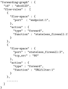
Finally, the flow-rules definition concludes the lowering process. In particular, (i) the connections among the VNFs, (ii) the traffic steering rules defined by the SG traffic split-ter/merger, and (iii) the ingress matching rules associated with the endpoints, are translated into a sequence of “flow-space/action” pairs (Figure 6). The flow space includes all the fields defined by Openflow 1.3 [22] (although new fields can be defined), while the action can be a forwarding rule either to a physical or a virtual port.
As a final remark, the FG does not specify all low level de-tails such as the physical node on which the service will be deployed, as well as the reference to the precise physical/ vir-tual NICs needed by the VNF to operate, which are replaced by generic VNF entry/exit points, as shown in Figure 6. The final translation from abstract to actual VNF ports will be carried out in the next step.
4.3. Infrastructure graph and reconciliation process
Theinfrastructure graph (IG)is the final representation of the service to be deployed, which is semantically, but not syn-tactically, equivalent to the FG. The IG is obtained through the reconciliation process, which maps the FG on the resources available in the infrastructure layer, and it consists of the se-quence of commands to be executed on the physical infrastruc-ture in order to properly deploy and connect together all the required VNFs.
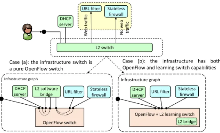
This process takes into account that some of the VNFs in the FG can be implemented through some modules (both software and hardware) already available on the node on which the graph is going to be deployed, instead of being implemented with the image specified in the template. For example, if the node is equipped with a virtual switch (vSwitch) that supports also the backward learning algorithm such as OpenvSwitch, all the L2 switch VNFs in the FG are removed and those functions are car-ried out through the vSwitch itself, as shown in the right portion of Figure 7. Instead, as depicted in the left of Figure 7, if the node features a pure Openflow vSwitch (such as xDPd), all the VNFs specified in the FG will be implemented by instantiat-ing the proper images, either VMs implementinstantiat-ing the L2 bridg-ing process or through a set of coordinated VMs implement-ing an OpenFlow switch controlled by an OpenFlow controller with the proper virtual LAN emulation software. Obviously, other mappings between the VNFs and the resources available on the node are possible, according to the specific capabilities of the infrastructure layer; for instance we can obtain a diff er-ent IG (hence a different number of deployed VNFs) starting from the same FG. The mapping of a VNF on a specific re-source is possible thanks to the definition of a set of standard VNF names that uniquely identify a precise network function, such as the name “L2 switch” that identifies a LAN emulation component; this allows the reconciliation module to recognize the function needed and, possibly replace it with a more appro-priate implementation.
After the reconciliation process, the final IG is converted into the commands (e.g., shell script, protocol messages) required to actually instantiate the graph, such as retrieve the VM image
URL filter DHCP server Stateless firewall W eb tr af fi c N o w eb tr af fi c OpenFlow switch Infrastructure graph
OpenFlow + L2 learning switch Infrastructure graph
L2 bridge
Case (a): the infrastructure switch is a pure OpenFlow switch
Case (b): the infrastructure has both OpenFlow and learning switch capabilities
DHCP server URL filter
Stateless firewall DHCP
server
L2 software bridge URL filter
L2 switch
Stateless firewall
Figure 7: Example of the output of the reconciliation process when mapping a L2 switch functionality in case of two different types of infrastructure nodes.
and start it up, create OpenFlow rules, and more. Particularly, the flow rules defining the links of the FG, i.e., the connections among the VNFs, are properly translated according to the tech-nology used by the physical node to implement the graph. For example, if the physical node interconnects the VNFs through an Openflow vSwitch, each flow rule is converted in a num-ber of Openflowflowmodmessages, hence combining together SDN and NFV concepts. However, other flavors of the in-frastructure layer could implement these connections through other technologies, such as GRE tunnels or VLAN tags. A sim-ilar process is applied to VNFs, as VM images are retrieved and started using commands that depend on the technology im-plementing the VNFs (e.g., virtual machine, Docker container, etc.).
4.4. Network function template
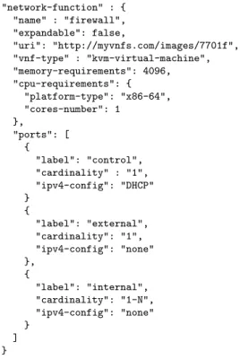
Each VNF is associated with a template that describes the VNF itself in terms of both physical characteristics (e.g., CPU and memory requirements) and possible infrastructure-level configurations (e.g., how many vNICs can be configured); an example of such a template is provided in Figure 8.
The template contains some information related to the hard-ware required to execute the VNF, such as the amount of mem-ory and CPU as well as the CPU instruction set. Moreover, the boolean elementexpandableindicates if the VNF consists of a single image, or if it is actually a subgraph composed of several VNFs connected together. In the former case, theuri
element refers to the image of the VNF, while in the latter it refers to a graph description that must replace the original VNF in the FG. In the case ofnon-expandableVNF, the template also specifies the image type such as KVM-compatible VM, Docker container, and more; for instance, the firewall described in Fig-ure 8 is implemented as a single KVM-based virtual machine.
Moreover, the template provides a description of the ports of the VNF, each one associated with several parameters. In par-ticular, thelabel specifies the purpose of that port, and it is useful in the definition of the SG, since it helps to properly con-nect the VNF with the other components of the service (e.g., the
externalport of the firewall should be connected towards the In-ternet, while theinternalones should be connected towards the
"network-function" : { "name" : "firewall", "expandable": false, "uri": "http://myvnfs.com/images/7701f", "vnf-type" : "kvm-virtual-machine", "memory-requirements": 4096, "cpu-requirements": { "platform-type": "x86-64", "cores-number": 1 }, "ports": [ { "label": "control", "cardinality" : "1", "ipv4-config": "DHCP" } { "label": "external", "cardinality": "1", "ipv4-config": "none" }, { "label": "internal", "cardinality": "1-N", "ipv4-config": "none" } ] }
Figure 8: Example of a VNF template.
users). The label could assume any value, which is meaningful only in the context of the VNF. The parameteripv4-config, instead, indicates if the port cannot be associated with an IPv4 address (none), or if it can be statically (static) or dynam-ically (DHCP) configured. Finally,cardinalityspecifies the number of ports of a certain type; for instance, the VNF of the example has onecontrolport, oneexternalport, and at least one
internalport (in fact, it has a variable number ofinternalports, which can be selected during the definition of the SG).
5. The validation use case: user-defined network services Section 3 and Section 4 respectively provide a general overview of the architecture and a description of the associ-ated data-models; those concepts could be used in different use cases involving multiple players in defining completely virtual-ized services.
In order to provide a concrete use case to validate our data models, we selected a challenging scenario in whichend users, such as xDSL customers, can define their own service graphs to be deployed on the telecom operator infrastructure. Particu-larly, an end user’s SG can only operate on the traffic of that par-ticular end user, i.e., on the packets he sends/receives through his terminal device. Vice versa, the telecom operator can define a SG that includes some VNFs that should operate on all the packets flowing through the network; hence, this SG must be shared among all the end users connected to the telecom opera-tor infrastructure.
Our use case presents some interesting challenges that can be solved through the multi-layer architecture and the data-models
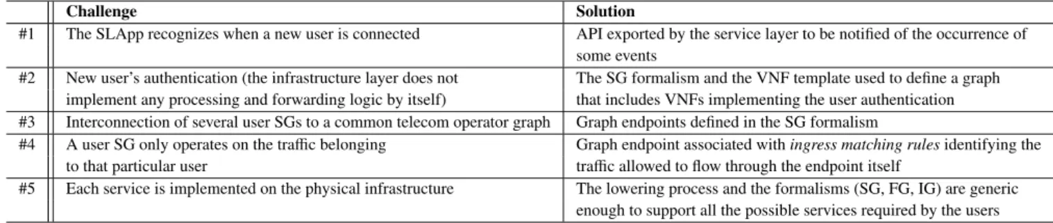
presented so far. These challenges, together with their solu-tions, are summarized in Table 1.
First, the service layer must be able to recognize when a new end user attaches to the network, and then to authenticate the user himself. The API exported by the service layer to the or-chestration layer (Section 3.1) could be exploited in our use case just for this purpose.
Note that, since the infrastructure layer does not implement any (processing and forwarding) logic by itself, the authentica-tion mechanism requires the deployment of a specific graph that only receives traffic belonging to unauthenticated users, and which includes some VNFs implementing the user authentica-tion. This could be implemented by means of the SG formalism detailed in Section 4.1, together with the VNF template (Sec-tion 4.4).
Second, after the user is authenticated, the service layer must retrieve his SG and then connect it to the telecom operator graph in a way so that the user traffic, in addition of being processed by the service defined by the user himself, is also processed by the VNFs selected by the telecom operator. Notably, the tele-com operator graph should be shared among different users, in order to reduce the amount of resources required by the service. The interconnection of two graphs in cascade can be realized by exploiting the graph endpoints elements provided by the SG formalism, as detailed in Section 4.1.1.
Third, the user SG must be completed with some rules to inject, in the graph itself, all the traffic coming from/going to-wards the end user terminal, so that the service defined by an end user (only) operates on the packet belonging to the user himself. Also this challenge has been solved thanks to the graph endpoints (Section 4.1), which can be associated with rules identifying the traffic that should enter into the graph through a particular endpoint.
Finally, the service layer must require (at the lower layers of the architecture) to deploy the user graph; this operation may require the creation of some tunnels on the network infrastruc-ture so that the user traffic is brought from the network entry point to the graph entry point, which could have been deployed everywhere on the physical infrastructure. The multi-layer ar-chitecture proposed in Section 3 ensures the deployment of all the SGs defined at the service layer, regardless of the particular services described by the graphs themselves. In fact, both the lowering process that transforms the SG in FG (Section 4.2), as well as the instructions provided to the infrastructure compo-nents through the IG (Section 4.3), are generic enough and can model all the possible services defined at the service layer. 6. Prototype implementation
This section presents the preliminary implementation of the architecture introduced in Section 3, detailing its components and the engineering choices that have been made in order to create the prototype.
6.1. The service layer
Our service layer logic is strictly related to our use case, in which the end users can define generic services to be applied
Table 1: Challenges of the considered use case and related solutions.
Challenge Solution
#1 The SLApp recognizes when a new user is connected API exported by the service layer to be notified of the occurrence of
some events
#2 New user’s authentication (the infrastructure layer does not The SG formalism and the VNF template used to define a graph
implement any processing and forwarding logic by itself) that includes VNFs implementing the user authentication
#3 Interconnection of several user SGs to a common telecom operator graph Graph endpoints defined in the SG formalism
#4 A user SG only operates on the traffic belonging Graph endpoint associated withingress matching rulesidentifying the
to that particular user traffic allowed to flow through the endpoint itself
#5 Each service is implemented on the physical infrastructure The lowering process and the formalisms (SG, FG, IG) are generic
enough to support all the possible services required by the users
to their own traffic, while the operator can define a service op-erating on all the packets flowing through the network. Our implementation of the SLApp delegates specific tasks to dif-ferent OpenStack modules, some of which have been properly extended. In particular,Horizon, the OpenStack dashboard, is now able to provide to the end users a graphical interface al-lowing them to express (out of band) the service they expect from the network, using the building blocks depicted in Fig-ure 3. Keystone, the token-based authentication mechanism for users and permissions management, is now able to store the user profile, which contains user’s specific information such as the description of his own SG. Finally, Swift, the OpenStack object storage, has been used to store the VNF templates. No-tably, those modules are present also in case of the integrated node implementation (Section 6.3), as the service layer is inde-pendent from the actual infrastructure layer.
At boot time, the SLApp asks the orchestration layer to in-stantiate two graphs, the telecom operator graph and the au-thentication graphs (Section 6.1.1), which are deployed on one of the available infrastructure nodes. In addition, it configures the network nodes with the proper rules to detect when a new flow is created on the network (e.g., a new user terminal at-taches to an edge node), which in turns triggers a call of the proper event handler in the SLAapp that forces an update of the authentication graph, so that it can properly handle the traffic generated from the new connected device. In fact, the SLApp has been notified about the source MAC address of the new packets, which can be used to uniquely identify all the traffic belonging to the new device. This enables the SLApp to up-date the authentication graph with a new endpoint representing the entry point of the user traffic in the network, and which is associated with an ingress matching rule expressed on the spe-cific MAC address; this way, the new packets can be provided to the authentication graph, wherever the graph itself has been deployed. Finally, the updated graph is passed to the orches-tration layer, which takes care of applying the modifications on the physical infrastructure.
A successful user authentication through the authentication graph triggers the instantiation of the SG associated with the user himself. This is achieved by the SLApp, which retrieves the proper SG description from the user profile repository, con-nects it to the telecom operator-defined SG such as in the exam-ple shown in the right part of Figure 4, and starts the lowering process aimed at creating the FG. In particular, the SLApp
ex-ecutes the “control and management network expansion” and the “LAN expansion” as shown in Figure 5(b), and the “ ser-vice enrichment” step. In our case, the latter consists in adding a DHCP server and a VNF implementing the NAT and router functionalities, in case these VNFs have not been included by the end user during the definition of his own service.
Before being provided to the orchestration layer, the user-side endpoint of the user SG is associated with (i)an ingress matching rule expressed on the MAC address of the user device, so that only the packets belonging to that user are delivered to his graph, and(ii)the entry point (i.e., the actual port on the physical edge node where the user connects to) of such a traffic in the telecom operator network. This way, the orchestration layer will be able to configure the network in order to bring the user traffic from its entry point into the network to the node on which the graph is deployed.
Finally, the SLApp also keeps track of user sessions in order to allow a user to connect multiple concurrent devices to his own SG. In particular, when a user already logged in attaches to the network with a new device, the SLApp: (i)retrieves the FG already created from the orchestration layer;(ii)extends it by adding a new endpoint associated with an ingress matching rule operating on all the traffic coming from the new device, and representing the entry point of such packets in the network;
(iii)sends the new FG to the orchestration layer.
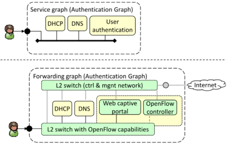
6.1.1. Authentication graph
Theauthentication graphis used to authenticate an end user when he connects to the telecom operator network with a new device, and it is automatically deployed by the service layer when the infrastructure starts, hence turning a service-agnostic infrastructure into a network that implements our use case.
The authentication SG (shown at the top of Figure 9) consists of a LAN connected to a VNF that takes care of authenticat-ing the users, a DNS server and a DHCP server. However, the VNF implementing the users authentication is in fact another SG made up of three VNFs: an Openflow switch, an Openflow controller and a web captive portal. The resulting FG, com-pleted with the control and management network, is shown at the bottom of Figure 9; as evident, only the control network is connected to the Internet while all the user traffic is kept local.
When an unauthenticated user connects to the network, his traffic is brought to the authentication graph. In particular, the DHCP server returns an initial IP address to the user, which is
Forwarding graph (Authentication Graph) User authentication
DHCP DNS
Service graph (Authentication Graph)
L2 switch (ctrl & mgnt network)
OpenFlow controller
Internet
DHCP DNS Web captive portal
L2 switch with OpenFlow capabilities
Figure 9: Authentication SG and FG.
able to generate traffic. All DNS queries are resolved by the DNS server into the proper IP addresses, but all the web re-quests are redirected to the captive portal; in fact, the HTTP traffic entering into the Openflow switch is sent to the Open-flow controller, which modifies the original MAC and IP desti-nation addresses with those of the web captive portal and then sends back the packet to the Openflow switch, which will de-liver it to the captive portal. This VNF provides a HTTP302
temporary redirect message to the user in order to notify
the client of the redirection and avoiding wrong caching, then a login page is shown. After the (successful) user authentication, the web captive portal contacts the SLApp through the control network and triggers the deployment of the SG associated with that user on the infrastructure.
6.2. Global orchestrator
The global orchestratorimplements the first two levels of the orchestration layer depicted in Figure 2 and consists of a technology-dependent and a technology-independent part.
The technology-independent part receives the FG from the service layer (through its northbound interface) and it executes the following operations as defined in the lowering process (Section 4.2). First, for each VNF specified in the graph, it retrieves the corresponding VNF template from the OpenStack Swift service. In case the template is actually a subgraph com-posed by other VNFs (Section 4.4), it executes the “VNFs ex-pansion” step (Figure 5(c)) and retrieves the description of the new VNFs that, in turn, could be recursively expanded in fur-ther subgraphs. The “VNFs consolidation” step follows, possi-bly consolidating multiple function instances as shown in Fig-ure 5(d). Finally, the “flow-rules definition” step creates a se-quence of “flow-space/action” pairs describing how to steer the traffic within the graph.
At this point, the global orchestrator schedules the FG on the proper node(s) of the physical infrastructure. Although the general model presented in Section 3.2 supports a scheduling based on parameters such as CPU and memory requirements of the VNFs, KQIs (e.g., maximum latency, expected through-put) and high level policies, the current implementation simply instantiates the entire FG on the same node used as a network
entry point for the traffic to be injected into the graph itself. The resulting FG is then provided to the proper control adapter, cho-sen based on the type of infrastructure node (i.e., OpenStack-based node or integrated node) that has been selected by the scheduler and that has to execute the FG. These adapters take care of translating the FG into the formalism accepted by the properinfrastructure controller, which is in charge of sending the commands to the infrastructure layer. Moreover, they con-vert the abstract endpoints of the graph (i.e., the ones that have not yet been translated into physical ports e.g., by the service layer) into physical ports of the node; finally, if needed, they instruct the infrastructure controller to create the required GRE tunnels. Tunnels can be used to connect together graphs that have been instantiated on two different nodes (graph cascad-ing), or to connect two portions of the same graph that have been deployed on different nodes (graph splitting). In our use case, a tunnel is required to bring the user’s traffic from the edge node he is connected to towards the node where the graph has been instantiated, as well as to bring the traffic generated by unknown user terminals to the authentication graph.
As a final remark, the global orchestrator supports the up-date of existing graphs. In fact, when it receives a FG from the service layer, it checks if this graph has already been de-ployed; in this case, both FGs (the one deployed and the new one) are provided to the proper control adapter, which sends to the infrastructure controller either the difference between the two graphs in case of integrated node, or both FGs in case of OpenStack-based node, as that implementation will be able to automatically identify the differences thanks to the OpenStack Heat module.
6.3. The integrated node
Theintegrated node[23] [24] is the first flavor of our in-frastructure layer and it consists of a single physical machine running mostly ad hoc software, whose overall architecture is shown in Figure 10. In this implementation, the infrastructure controller isintegratedon the same server running the VNFs. Multiple integrated nodes are possible on the infrastructure and must be coordinated by the global orchestrator.
The integrated node receives the FG through the northbound (REST) interface of thenode resource manager, which is the component that takes care of instantiating the graph on the node itself; this requires to execute the reconciliation process in or-der to obtain the IG, to start the proper VNF images (down-loaded from aVNFs repository) and to configure the proper traffic steering among the VNFs. Particularly, the last two op-erations are executed through two specific modules of the node resource manager, namely thecompute controllerand the net-work controller.
Traffic steering is implemented with a (pure) Openflow DPDK-enabled datapath, based on theextensible Data-Path deamon (xDPd) [25]. xDPd supports the dynamic creation of several Openflow switches, called Logical Switch Instances (LSIs); each LSI can be connected to physical interfaces of the node, to VNFs, and to other LSIs. A different LSI (called
Integrated Node
LSI - 0 Node resource manager
VNF1
...
Virtual link among LSIs
Openflow connection Network function port (between an LSI and a VNF)
xDPd OF controller LSI tenant N OF controller LSI tenant 1 OF controller LSI 0 LSI - Tenant 1 VNF repository Management connection VNF5 [FG] Network controller Compute controller DPDK driver Docker driver VM driver libvirt VNF4 VNF3 Compute control LSI - Tenant N VNF2
Figure 10: Logical architecture of the integrated node.
of a specific graph, while the LSI-0is in charge of classify-ing the traffic coming from the network (or from other graphs) and of delivering it to the propertenant-LSI. TheLSI-0is the only one allowed to access the physical interfaces, and the traffic flowing from onetenant-LSI to another has to tran-sit through theLSI-0as well. Since LSIs arepureOpenflow switches, the reconciliation process described in Section 4.3 cannot remove the L2Switch VNFs, which are then imple-mented using the proper software images because of the un-availability of the backward learning algorithm in xDPd.
When a FG description (either a new one or an update of an existing FG) is received by the node resource manager, this module: (i)retrieves a software image for each VNF required and installs it;(ii)instantiates atenant-LSIon xDPd and con-nects it to the LSI-0and to the proper VNFs; (iii) creates a new OpenFlow controller associated to the tenant-LSI that is in charge of inserting the required forwarding rules (i.e., traffic steering), which sets up the proper connections among VNFs as required by the FG. In particular, the FG rules that define the paths among VNFs (and physical ports) originate two se-quences of Openflowflowmodmessages: one to be sent to the
LSI-0, so that it knows how to steer traffic among the graphs
deployed on the node and the physical ports; the other used to drive thetenant-LSI, so that it can properly steer the packets among the VNFs of a specific graph.
When a packet enters into the LSI-0 and cannot be for-warded to anytenant-LSI, it is delivered to theLSI-0 con-troller using the Openflow packet inmessage; at this point the Openflow controller notifies the service layer of the pres-ence of a new user terminal, which will react by creating the proper network setup (e.g., tunnels) to redirect that traffic to the authentication graph.
The integrated node supports three flavors of VNFs: DPDK processes [26], Docker containers [27], and VMs. While the former type provides better performance (in fact, an LSI ex-changes packets with DPDK VNFs with a zero-copy mecha-nism), Docker containers and VMs guarantee better isolation among VNFs, as well as they allow to limit CPU and mem-ory usage. Data exchange between LSIs and Docker contain-ers/VMs takes place through theKNIvirtual interface available with the DPDK framework.
Finally, the architecture of the integrated node can support
In fr as tr uc tur e con tr ol ler
Generic network device (router, switch, …) Nova compute agent Docker libvirt Nova Compute node OpenStack Neutron Network API Modular layer 2 (ML2) […] [OVS] ODL OpenStack Nova Compute API Nova scheduler OpenDayLight Network controller OpenStack Heat
[FG (Heat JSON format)]
VNFs repository (OpenStack
Glance)
[Openflow / OVSDB] [OS Nova on RabbitMQ]
[ODL REST interface]
VM KVM
OpenvSwitch
OpensStack compute domain
Figure 11: OpenStack-based node.
a network-aware scheduling algorithm, which has the potential to optimize the location of each VNF based on the I/O con-nections of the VNF itself. This allows for example to start two cascaded VNFs on two cores of the same physical CPU in order to keep the traffic within the same NUMA node, or to allocate a VNF on the CPU that is connected to the NIC used to send the packet out to the network. This is possible because the node resource manager, which takes care of both deploy-ing the VNFs and configurdeploy-ing the vSwitch to properly steer the traffic among them, receives the entire FG from the upper layer, which describes both the VNFs to be executed and the connec-tions among them.
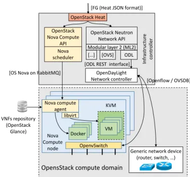
6.4. The OpenStack-based node
TheOpenStack-based nodeis the second flavor of our in-frastructure layer and it consists of a cluster of servers within the same OpenStack domain. As shown in Figure 11, all the physical machines of the cluster are managed by a single infras-tructure controller, which is composed of a number of Open-Stack modules and a SDN controller. Multiple OpenOpen-Stack- OpenStack-based nodes are possible on the infrastructure and must be co-ordinated by the global orchestrator.
OpenStack [18] is a widespread cloud toolkit used for man-aging cloud resources (network, storage, compute) in data-centers; hence, its support in our architecture represents an in-teresting choice because of the possibility to deploy our ser-vices in an existing (and widely deployed) environment. How-ever, since OpenStack was designed to support the deployment ofcloudservices, several modifications have been made to sup-port FGs (hencenetworkservices) as well.
As depicted in Figure 11, our OpenStack-based node exploits the following components: (i)Nova, the compute service;(ii)
and(iv)Glance, the VM images repository. Openstack is able to start VMs by interacting with a wide range of different hyper-visors (e.g. KVM, Xen, VMware); moreover, in order to prop-erly steer the traffic between the several servers under its control our prototype integrates also the OpenDaylight (ODL) [28] SDN controller. As evident from the picture, Heat, Nova sched-uler, Nova API, Neutron and ODL compose the infrastructure controller, while each physical machine executing the VNFs is a Nova compute node, which runs a Nova compute agent, the OpenvSwitch (OVS) [29] softswitch and theKVM hypervi-sor.
When the global orchestrator decides to deploy a FG in an OpenStack-based node, the proper control adapter translates the FG description into the format supported by Heat. To be used in our prototype, Heat has been extended in order to support the
flow-rule primitive, which describes how to steer the
traf-fic between the ports of the VNFs composing a graph. This primitive provides an interface similar to the OpenFlow 1.3
flowmod; however, it allows the traffic steering between
vir-tual ports without knowing in advance the physical server on which the respective VNFs will be scheduled. As soon as Heat receives the FG, it performs a reconciliation step that removes, from the graph itself, all the VNFs implementing the L2 switch, since this functionality will be mapped on the OVS instances running on the physical servers. In fact, OVS is able both to forward traffic based on traffic steering rules, as well as to exe-cute the MAC learning algorithm. After this translation, the FG is decomposed into a set of calls to Nova and Neutron.
For the compute part, Nova receives a sequence of com-mands for each VNF of the graph in order to deploy and start the VNF itself; at this point, the Nova scheduler(i)selects the physical server on which the VNF must be deployed using the standard OpenStack “filter & weight” algorithm2,(ii)sends the proper command to the Nova compute instance on the selected node, which in turn(iii)retrieves the VNF image from Glance and finally (iv) starts the VM3. It is worth noting that Nova scheduler has two limitations: (i)it schedules a VNF as soon as it receives the command from Heat;(ii)it does not have any information on the paths among the VNFs in the graph. As a consequence, the FG could be split on the available compute nodes without taking into account the paths among the VNFs, clearly resulting in suboptimal performance.
For the networking part, when Heat detects that all the VNFs (i.e., VMs) are started, Heat sends a flow-ruleat a time to Neutron, which takes care of creating the proper connections among these VNFs. Similarly to Heat, also Neutron has been extended to support theflow-ruleprimitive4. When Neutron
2This algorithm acts as follows: first, all the Nova compute nodes that are
not able to run a VM are filtered (e.g., because the VM requires an hypervisor that is not available on the node). Then, a weight is associated with each one of the remaining servers, and the one with higher weight is selected to run the VM. The weights are calculated by considering the resources available on the machine.
3Note that no modification has been required by Nova compute in order to
support the deployment of the FGs.
4The
flow-ruleis functional equivalent to the Neutron official traffic
steer-ing extension [19]. However, it has not been used in our prototype because:(i)
receives aflow-rule, it retrieves the network topology from ODL and then creates the proper Openflowflowmodmessages required to steer the traffic on the physical infrastructure. At this point, the flowmods are provided to ODL, which sends them to the proper switches; note that these switches could be either inside a Nova compute node, or physical switches used to interconnect several servers, in case the VNFs have been in-stantiated by the Nova scheduler on many compute nodes.
In addition to the components described so far, each Open-Stack deployment also includes thenetwork node, which is a particular server running some services such as a NAT, a DHCP server, a load balancer and a router; moreover, by default it is crossed by all the traffic entering/leaving the cluster of servers.
Similarly to the integrated node, also the OpenStack-based node notifies the service layer when a new user terminal con-nects to the node itself in order to allow the system to redirect that traffic to the authentication graph.
6.5. Discussion: Openstack-based node vs. integrated node
Table 2 summarizes the main differences between the inte-grated node and the OpenStack-based node. As shown, the main advantage of the latter is its capability to deploy SGs in an existing cloud environment (albeit with some modifica-tions), which facilitates the introduction of those services in telecom operator networks; in fact, operators often already have OpenStack instances active in their data centers. However, this very important advantage is balanced by severe limitations compared to the integrated node.
First, OpenStack does not allow the service layer to have the complete control of the service chain, as each OpenStack domain is connected to the Internet through thenetwork node
(Section 6.4) and all the packets towards/from the Internet are forced to traverse the network services running in this compo-nent (e.g., NAT and router), even if the SG does not include those functions.
Second, the OpenStack-based node cannot optimize the placement of the VNFs based on their layout in the FG, e.g., possibly instantiating two consecutive VNF within the same graph on the same physical server. This is due to the fact that the OpenStack scheduler, implemented in Nova, is unaware of the overall layout of the FG: this information is only received by Heat and it is not passed down to the Nova scheduler. To make things worse, the Nova scheduler is invoked individually per each VNF that has to be scheduled and therefore it is unable to implement even a simple optimization such as scheduling all the VNFs of the same FG on the same server. This problem is not present in the integrated node as it receives the entire FG, hence it has all the information related to the required VNFs and the paths among them, hence potentially scheduling the VNFs on the available CPUs by considering their position in the graph, with the obvious advantages in terms of overall per-formance.
it was not available when this prototype was created (July 2014);(ii)it does not support ports that do not belong to a VM.
Table 2: Integrated node vs OpenStack-based node.
Integrated node OpenStack-based node
Compatible with existing No Yes
cloud environments
Complete control of the FG Yes No (due to the network node)
Support to smart scheduling of the FG Possible Requires many changes to the OpenStack internals
Type of VNFs Docker containers, DPDK processes, VMs VMs, Docker containers (not completely supported)
Third, the integrated node shows better memory consump-tion compared to the OpenStack-based node, whose compo-nents have not been created for resource-constrained environ-ments as this is unlikely to occur in (almost resource-unlimited) data centers.
Finally, the OpenStack-based node supports only VM-based VNFs, as the initial support for Docker containers appears still rather primitive. Vice versa, the integrated node supports VNFs implemented as Docker containers, VMs and DPDK pro-cesses, which seems to suggest the possibility to write more lightweight and efficient VNFs, particularly with respect with the potentially better I/O capabilities, which represent a fun-damental difference from VNF and traditional VM-based ser-vices.
7. Prototype validation
To validate the architecture described in the paper, we carried out several tests aimed at both testing the functionalities imple-mented, and to measure the performance of the infrastructure layer in terms of throughput, latency introduced and resource required. The tests were repeated both with an infrastructure layer consisting of a single integrated node, as well as in case of an OpenStack cluster composed by two compute nodes. Note that, in the latter case the graphs are split so that the VNFs are distributed between the two physical servers.
7.1. Service overview
The FGs deployed in the tests are shown in Figure 12; ac-cording to our use case, these graphs include the authentica-tion graph used to authenticate new end users connected to the network, and the telecom operator graph, which provides con-nectivity to the Internet and that is crossed by the traffic gener-ated from/going towards all the end users. The control network of this telecom operator graph also includes a firewall, so that only the authorized entities (e.g., the telecom operator itself) can control and configure the deployed VNFs.
The end user graph provides an example of traffic steering, since it requires that the web traffic is delivered to a traffic mon-itor and then to a firewall that blocks the HTTP GET towards specific URLs, while the other packets simply traverse a second traffic monitor VNF. Thanks to the control interface of the traf-fic monitors we are able to observe the packets flowing through the specific VNF, and hence to validate the correct behavior of the traffic steering mechanism.
Authentication Graph User Blue FG Service provider FG Traffic monitor Traffic monitor DHCP
L2 switch (ctrl & mgnt network)
L2 switch
no web
web NAT
DHCP NAT L2 switch with OpenFlow capabilities
L2 switch (ctrl & mgnt network) Flow rule: MAC blue Flow rule: * - { MAC blue} L2 switch Firewall L2 switch (ctrl & mngt) Firewall DHCP DNS OpenFlow controller Web captive portal
Figure 12: Use case scenario.
During the tests carried out on the OpenStack-based node, the VNFs are implemented as VMs running on the KVM hy-pervisor. In contrast, in the tests with the integrated node, the firewall is implemented as a DPDK process5, while all the oth-ers VNFs are implemented as Docker containoth-ers. In particular, both the VMs and the Docker containers run an Ubuntu oper-ating system, and the VNFs are implemented throughstandard
Linux tools (e.g.,iptables).
As a final remark, according to our use case and the current implementation of the architecture, the end users are directly connected to the node on which their graphs are deployed.
7.2. Performance evaluation
This section shows the tests executed in order to measure the performance of the preliminary implementation of our architec-ture.
During the tests, a machine is dedicated to the execution of the service layer (i.e., SLApp, Keystone and Horizon) and the global orchestrator; it is equipped with 16 GB RAM, 500GB HD, Intel i7-2620M @ 2.7 GHz (one core plus hyperthreading) and OSX 10.9.5, Darwin Kernel Version 13.4.0, 64 bit, which is the same for both the infrastructure nodes.
The infrastructure layer is implemented on a set of servers with 32 GB RAM, 500GB HD, Intel i7-3770 @ 3.40 GHz CPU (four cores plus hyperthreading) and Ubuntu 12.04 server OS, kernel 3.11.0-26-generic, 64 bits. In case of the integrated node, one of those machines executes all the software. In case of OpenStack-based node, a first machine hosts the infrastructure controller (Heat, Nova scheduler, Nova API, Neutron and ODL)
5Note that this firewall is a quite simple single thread process based on the
libpcreregular expression engine, which drops all the packets matching