HAL Id: hal-02089064
https://hal-centralesupelec.archives-ouvertes.fr/hal-02089064
Submitted on 3 Apr 2019
HAL
is a multi-disciplinary open access
archive for the deposit and dissemination of
sci-entific research documents, whether they are
pub-lished or not. The documents may come from
teaching and research institutions in France or
abroad, or from public or private research centers.
L’archive ouverte pluridisciplinaire
HAL
, est
destinée au dépôt et à la diffusion de documents
scientifiques de niveau recherche, publiés ou non,
émanant des établissements d’enseignement et de
recherche français ou étrangers, des laboratoires
publics ou privés.
Deep Learning for UL/DL Channel Calibration in
Generic Massive MIMO Systems
Chongwen Huang, George Alexandropoulos, Alessio Zappone, Chau Yuen,
Mérouane Debbah
To cite this version:
Chongwen Huang, George Alexandropoulos, Alessio Zappone, Chau Yuen, Mérouane Debbah. Deep
Learning for UL/DL Channel Calibration in Generic Massive MIMO Systems. Internation Conference
on Communications (ICC), May 2019, Shanghai, China. �hal-02089064�
Deep Learning for UL/DL Channel Calibration
in Generic Massive MIMO Systems
Chongwen Huang
1, George C. Alexandropoulos
2, Alessio Zappone
3, Chau Yuen
1, and M´erouane Debbah
2,31Singapore University of Technology and Design, 487372 Singapore emails: chongwen [email protected], [email protected]
2Mathematical and Algorithmic Sciences Lab, Huawei Technologies France SASU,92100 Boulogne-Billancourt,France emails:{george.alexandropoulos, merouane.debbah}@huawei.com
3CentraleSup´elec, Universit´e Paris-Saclay, 91192 Gif-sur-Yvette, France email: [email protected]
Abstract—One of the fundamental challenges to realize massive multiple-input multiple-output communications is the accurate acquisition of channel state information for a plurality of users at the base station. This is usually accomplished in the UpLink direction profiting from the Time Division Duplexing mode. In practical base station transceivers, there exist inevitably non-linear hardware components, like signal amplifiers and various analog filters, which complicates the calibration task. To deal with this challenge, we design a deep neural network for channel calibration between the uplink and downlink directions. During the initial training phase, the deep neural network is trained from both uplink and downlink channel measurements. We then leverage the trained deep neural network with the instan-taneously estimated uplink channel to calibrate the downlink one, which is not observable during the uplink transmission phase. Our numerical results confirm the merits of the proposed approach, and show that it can achieve performance comparable to conventional approaches, like the Agros method and methods based on least squares, that however assume linear hardware behavior models. More importantly, considering generic nonlin-ear relationships between the uplink and downlink channels, it is demonstrated that our deep neural network approach exhibits robust performance, even when the number of training sequences is limited.
Index Terms—Channel calibration, deep learning, massive MIMO, multilayer neural networks, nonlinear hardware model.
I. INTRODUCTION
Massive Multiple-input Multiple-Output (MIMO) is already considered as a core physical layer component for fifth Gener-ation (5G), and beyond, broadband wireless networks [1]–[3]. It refers to the deployment of very large number of antenna elements at the Base Station (BS), which are intended to simultaneously serve multiple User Equipments (UEs). As it has been shown, massive MIMO can drastically improve the spectral efficiency of cellular networks [3], [4]. To achieve its theoretical gains, this technology necessitates accurate knowledge of the channels between the BS and each user, in order for the former to realize optimum DownLink (DL)
The work of C. Yuen was supported by the MIT-SUTD International design center and NSFC 61750110529 Grant, and that of C. Huang by the PHC Merlion PhD program. The work of M. Debbah was supported by H2020 MSCA IF BESMART, Grant 749336, and H2020-ERC PoC-CacheMire, Grant 727682; the former project also funded the work of A. Zappone.
precoding. Leveraging the Time Division Duplexing (TDD) mode [2], this knowledge can be efficiently acquired from the UpLink (UL) direction via orthogonal training signals simultaneously sent from the UEs to BS. The UL channels are first estimated, and then exploiting channel reciprocity [5], they are mapped to DL channels.
In practice, however, although in TDD mode the UL and DL wireless propagation channels are physically reciprocal [6], the analog front-end circuitry for transmission and reception at the BS and users are not in general [7]–[9]. This complicates the application of the massive MIMO paradigm, rendering the effective baseband-to-baseband UL and DL channels non-reciprocal. To rely on the channel reciprocity assumption, and consequently, utilize the UL Channel State Information (CSI) estimation to compute the DL precoding vectors, the non-reciprocal transceiver responses need to be appropriately calibrated [10]–[15]. This process is often termed as channel calibration, and usually includes two procedural steps: i) estimation of the calibration coefficients between the UL and DL channels; and ii) calibration compensation by applying those coefficients to the UL channel estimates in order to obtain the estimation of the DL channels.
Channel calibration of TDD MIMO channels with small numbers of antennas has been a matter of study in recent years. Depending on the system setup and requirements, the approach adopted can take many forms. For example, [7] proposed a methodology based on bidirectional measurements between the two ends of a MIMO link to estimate suitable reciprocity calibration coefficients. This calibration approach falls into the class of Over-The-Air (OTA) calibration schemes, where users are involved in the calibration process. Recently, the authors in [16] working on the massive MIMO Argos prototype performed OTA calibration with the help of a reference antenna. The Argos calibration approach, however, is sensitive to the location of the reference antenna, and as a consequence, it is not suitable for distributed massive MIMO scenarios. As an improved method, [17] proposed a novel family of calibration schemes based on antenna grouping, which can greatly speed up the calibration process with respect to the classical approaches. In addition, some experimental data about the calibration coefficients were recently reported
TDL Base Station (M antennas) User Equipment (single antenna) hDL hUL RUL cUL cDL tUL rDL wDL wUL
Figure 1. The considered model for bidirectional links (DL and UL direc-tions) between aM-antenna base station and single-antenna user equipment.
in [17], [18], giving an insight on how the impairments evolve in the time and frequency domains as well as with temperature. In the latter two papers, the hardware characteristics behind those coefficients were also discussed.
Deep learning methods have demonstrated significant im-provements in various application fields in the last years. These methods are capable of outperforming human-level object detection in some tasks [19], and achieve state-of-the-art results in machine translation [20] and speech processing [21]. Additionally, deep learning combined with reinforcement learning techniques was able to beat human champions in challenging games, such as the Go [22]. Very recently, deep learning methods have been also proposed for communication systems. For instance, various channel decoders using deep learning techniques were proposed in [23], [24]. In [25], it was proposed to learn a channel auto-encoder via deep learning tools. However, the use of deep learning methods for channel calibration in MIMO systems has not been investigated, yet.
In this paper, we propose a deep learning framework for calibration between UL and DL channels in massive MIMO systems. The proposed framework is rather general, targeting at training a Deep Neural Network (DNN) to learn the, possibly nonlinear, relationship between UL and DL channels. To this end, our designed DNN can be applied to generic TDD and Frequency Division Duplexing (FDD) massive MIMO systems with nonlinear hardware transceivers. During the training phase, the DNN is trained from both UL and DL training measurements. Then, the trained network is used to carry out the calibration task for yet unobserved channels. Compared with existing methods [16], [17] that are limited to linear UL/DL relationships, it is shown via simulations that our DNN design approaches the Cram´er-Rao Bound (CRB). Moreover our DNN approach exhibits robust performance, even when the number of training sequences is limited.
II. SYSTEMMODEL
In this section, we introduce our considered generic massive MIMO system model together with the special case of linear channel model for TDD operation.
A. Generic System Model
In practical communication systems, the UL and DL baseband-to-baseband channels between any pair of nodes are usually nonlinear, due to the front-end hardware at Transmitter (TX) and RX. For example, nonlinear solid-state devices, like signal power and low noise amplifiers, are modeled as
memoryless devices whose nonlinearity appears when the instantaneous input signal power fluctuates and approaches the saturation level of the device [26]. Other nonlinear devices, such as fiber optics, are usually modeled as nonlinear functions with memory, and their nonlinear effects originate from the physical limitations of the communication channel [27].
Let us consider the bidirectional link depicted in Fig.1 be-tween anM-antenna BS and a single-antenna User Equipment (UE). The upper part of the figure showcases the DL commu-nication from BS to UE, whereas the lower part illustrates the UL communication from UE to BS. The M ×M complex-valued matrices TDL and RUL represent the responses of the BS Radio Frequency (RF) front-ends of the transmit and receive modes, respectively. The diagonal elements in these matrices represent the linear effects attributable to the impairments in the TX and RX parts of the RF front-ends, respectively, whereas their off-diagonal elements correspond to RF crosstalk and possible antenna mutual coupling. The complex scalarstDLandrULrepresent the responses of the UE RF front-end of the transmit and receive modes, respectively. Notations cDL ∈ C1×M and cUL ∈ CM×1 denote the OTA wireless propagation channels in the DL and UL directions, re-spectively. Without loss of generality, in this paper, we assume frequency flat channels, as typically occuring in narrowband communications or in a single subcarrier of a multi-carrier system. We have used hDL ∈ C1×M and hUL ∈ CM×1 to indicate the DL and UL propagation channels, respectively, in digital baseband. Finally,wUL∈CM×1denotes the Additive White Gaussian Noise (AWGN) vector at BS, while the complex scalar wDL is the AWGN at the UE side.
Suppose that N single UEs simultaneously transmit or-thogonal pilot symbols in the UL to the M-antenna BS. By collecting all pilot symbols in the vector xUL , [x(1)ULx(2)UL · · ·xUL(N)]T, wherex(n)UL denotes the pilot symbol of the n-th UE withn= 1,2, . . . , N, theM-element complex-valued received signal at the BS antenna elements can be expressed in the general case as
yUL=f(HUL,xUL) +wUL, (1) where HUL , [h (1) ULh (2) UL · · ·h (N) UL] ∈ CM×N (column con-catenation) with h(n)UL ,[h(1,n)UL h(2,n)UL · · · h(M,n)UL ]T ∈ CM×1 being the channel between BS and the n-th UE. Also, f(·) denotes a general nonlinear function ofHUL andxUL.
When DL channel estimation is the objective, the BS sequentially transmits the orthogonal pilot symbols vector
xDL,[x (1) DLx (2) DL · · ·x (M) DL ]
T to each of theN single-antenna UEs, withx(m)DL representing the pilot symbol transmitted from the m-th BS antenna. In this case, the N-element complex-valued vector including the received signals at all UE is given by the general expression
yDL=g(HDL,xDL) +wDL, (2) whereg(·)is a general nonlinear function of the DL baseband-to-baseband channel HDL , [h (1) DL;h (2) DL;· · · ;h (N) DL] ∈ CN×M (row concatenation) and xDL, and wDL ,
[wDL(1)w(2)DL · · ·wDL(N)] ∈ CN×1 represents the vector with the AWGN values at all N UEs.
B. Special Case: The Linear TDD Communication
State-of-the-art channel calibration methods [7], [16]–[18] assume a linear relationship between the transmitted and received signals. Then, recalling our frequency flat channel model assumption, the received signals at the BS in the UL direction and at all UEs in the DL direction can be respectively expressed using (1) and (2) as
yUL=HULxUL+wUL, (3)
yDL =HDLxDL+wDL. (4) By further assuming that our massive MIMO system operates in TDD mode, channel reciprocity holds for every link be-tween BS and the n-th UE, i.e.,c(n)UL= (c(n)DL)T. In this case, the baseband DL and UL channels for every latter n-th link are respectively given according to Fig.1 as
h(n)DL =rDL(n)c(n)DLT(n)DL, (5)
h(n)UL =R(n)UL(c(n)DL)Tt(n)UL, (6) and hence, they can be easily related as follows:
h(n)DL =r(n)DLc(n)DLT(n)DL, =r(n)DL((R(n)UL)−1hUL(n)(t(n)UL)−1)TT(n)DL, =r(n)DL(t(n)U L)−1 | {z } ,a(n) (h(n)UL)T(R(n)UL)−TT(n)DL | {z } ,B(n) , =a(n)(h(n)UL)TB(n). (7) The OTA channel reciprocity calibration for the case of massive MIMO TDD systems has the following two phases. In the first phase, the calibration process is performed which includes the estimations of the complex-valued scalara(n)and
B(n)∈CM×M appearing in (7) ∀n. Then, during the second data transmission phase, the latter matrices are used together with the instantaneously measured UL channels h(n)UL ∀n to estimateh(n)DL ∀naccording to (7).
III. DNN-BASEDCHANNELCALIBRATION
In this section, we present a DNN-based channel calibra-tion approach for generic massive MIMO systems, which is fully data driven. It comprises a training phase to obtain the designed DNN’s parameters, followed by the online channel calibration phase that feeds UL channel estimation to the DNN, which finally outputs the predicted DL channels.
A. Deep Learning Basics
Suppose that θ , {θ1, θ2, . . . , θL} includes L sets of pa-rameters. A feedforward DNN (or multi-layer perceptron) with Llayers describes a mappingF(r0,θ) :RN0×17→
RNL×1 of
the input vector r0 ∈ RN0×1 to an output vector in RNL×1
through the following Literative processing steps:
r`,f`(r`−1;θ`), `= 1,2, . . . , L, (8) ●●● ●● ● ●● ● ●● ● ●● ● Input Output
Input layer Hidden layer Hidden layer Hidden layer Output layer
Figure 2. The proposed Calinet DNN for channel calibration in generic massive MIMO systems comprising of five layers.
wheref`(r`−1;θ`) :RN0×17→
RNL×1represents the mapping
carried out by the `-th DNN layer. This mapping depends on the output vectorr`−1from the previous(`−1)-th layer and on a set of parametersθ`. In general, the mappingf`(·;·)can be stochastic, i.e., it can be a function of random variables. The` -th DNN layer is called dense or fully-connected if all neurons in this layer are connected to all neurons in the following layer. In this case,f`(r`−1;θ`)withθ`,{W`,b`} has the form:
f`(r`−1;θ`) =σ(W`r`−1+b`), (9) where W` ∈ RN`×(N`−1) denotes the neurons’ weights at
this layer, b` ∈ RN`×1 stands for the bias vector, and σ(·)
represents a so-called activation function.
B. Proposed DNN Massive MIMO Channel Calibration
According to the universal approximation theorem [28], a feed-forward neural network with a fully-connected single hid-den layer can approximate continuous functions on compact subsets ofRN×1. As a standard multi-layer processor, a DNN is capable of approximating any continuous function to any desired degree of accuracy. Our proposed DNN for channel calibration in generic massive MIMO systems, namedCalinet, is illustrated in Fig. 2. It consists of five layers; namely, the input layer, three hidden layers, and the output layer. In particular, there exist multiple neurons in each hidden layer, and each layer’s output is a nonlinear function of a weighted sum of the values of the neurons at the input of this layer. As shown in Fig.2, Calinet’s input layer consists ofM Nneurons, which forward the instantaneous channel coefficients inHUL to the first hidden layerl1. The role of the hidden and output layers is to capture the relationship between HUL andHDL. In all layers, we have usedtanh(·)as activation functionσ(·), since it works well with approximations of nonlinear functions and provides full mapping in [−1,1].
The proposed DNN-based massive MIMO channel calibra-tion works as illustrated in Fig. 3. First, the DNN of Fig. 2 undergoes a training phase, and then, the trained DNN is used for online channel calibration. More specifically:
Base Station Physical
Channel UEs Estimated
via Pilots Predicted
Calinet Weights Bias Calibrating Phase Training Phase Calinet Estimated via Pilots
Figure 3. Schematic of the proposed procedure for deep learning based massive MIMO channel calibration using the Calinet DNN in Fig.2.
1) Training Phase: In this phase, pilot signals are used in both the DL and UL directions to obtain P pairs of bidirectional channel estimations; let(HDL,p,HUL,p) denote thep-th pair, withp= 1,2, . . . , P, of UL and DL channel estimations. Then, this P-element training set is fed to Calinet and a training algorithm is deployed to adjust the DNN’s parametersθ. This process is detailed in the following subsection.
2) Channel Calibration Phase: The trained Calinet from the previous phase is used to predict DL channels from UL channel estimations. The UL channel estimation HUL obtained from UL pilots is fed to Calinet that outputs the predicted DL channels. We denote those channels by
ˆ HDL ,[hˆ (1) DL;hˆ (2) DL;· · ·;hˆ (N) DL]∈C N×M. C. DNN Training Process
In the beginning of the training phase, the desired inputs {HUL,p}Pp=1 and desired outputs {HDL,p}Pp=1 of the DNN Calinet are obtained via dedicated channel sounding. After-wards, the weights and bias of Calinet’s layers are designed in order to minimize the Minimum Mean Squared Error (MMSE) between the P actual outputs {HˆDL,p}Pp=1 of the DNN and the P desired outputs{HDL,p}Pp=1, namely
L(HˆDL,p(θ),HDL,p) = = P X p=1 kvec(HˆDL,p(θ))−vec(HDL,p)k2 (10)
where θ ,{θ1,θ2, . . . ,θ5} with θ` ={W`,b`}. Notation
ˆ
HDL,p(θ) indicates that the actual DNN vector output is a function of the network’s parametersθand of course its input vector HUL,p.
In order to minimize (10) with respect toθ, several off-the-shelf training algorithms can be used, that employ variations of the stochastic gradient descent methods, where at each step the gradient of the cost function is estimated from a randomly-selected subset of training samples, called mini-batch. Thus, at each gradient iteration, the DNN parameters are updated as
θ=θ−η∇L(b θ), (11)
where ∇L(b θ) denotes the estimated gradient, and η the
algorithm learning rate. Moreover, at each step, gradients are
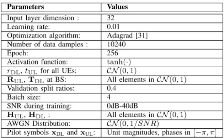
Table I
PARAMETERS FORCALINETDESIGN ANDSIMULATIONS
Parameters Values
Input layer dimension : 32 Learning rate: 0.01 Optimization algorithm: Adagrad [31] Number of data damples : 10240
Epoch: 256
Activation function: tanh(·) rDL,tULfor all UEs: CN(0,1)
RUL,TDLat BS: All elements inCN(0,1)
Validation split ratios: 0.4
Batch size: 4
SNR during training: 0dB-40dB
HUL,HDL: All elements inCN(0,1)
AWGN Distribution: CN(0,1/SN R)
Pilot symbolsxDLandxUL: Unit magnitudes, phases in[−π, π]
efficiently computed by means of the backpropagation method [29]. Specifically, the proposed DNN Calinet has been trained by means of the Adagrad algorithm [31].
IV. NUMERICALRESULTS
For our numerical analysis, we consider a massive MIMO system comprising a BS withM = 32 antenna elements and N = 4single-antenna UEs. Considering the linear TDD case of Sec.II-B, we compare the performance of the Argos [16] method and the Norm plus Phase Constraint First Coefficient (NPC FC-II) [17] method, as well as the method in [11] with that of the proposed DNN approach presented in Secs. III-B and III-C. Moreover, we also report the CRB, which can be obtained in closed form following similar steps as in [17]. We have also investigated the calibration performance of the proposed DNN approach for generic nonlinear scenarios, for which no other method is available. The simulation parameters and the parameters for the designed Calinet are summarized in Table I, where SNR denotes the Signal-to-Noise Ratio and CN(0, λ) represents the circularly symmetric complex Gaussian distribution with zero mean and variance λ. A total of500 independent channel realizations were generated for the results that follow, which were obtained using the deep learning library TensorFlow [32] and MATLABTM. For the DNN approach, the considered data set was randomly partitioned into the training set (60% of the total samples) and the test set (40% of the total samples).
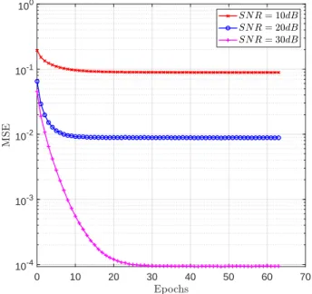
In Fig. 4, the Mean Squared Error (MSE) performance between the actual HDL and the HbDL obtained using all considered calibration methods is plotted as a function of the SNR in dB. As shown, all methods share the same decreasing MSE trend when SNR increases. Although the NPC FC-II algorithm achieves the best MSE performance since it is sufficiently close to CRB, the proposed DNN approach outperforms the Argos method and the approach from [11], exhibiting only a limited gap from CRB, despite the limited size of the training set. In Fig.5, we sketch the iteration behavior of the DNN training process for three different SNR values. It can be seen that MSE decreases drastically with more iterations and reaches a floor that becomes lower as the SNR increases. In addition, the lower the SNR the faster is
0 5 10 15 20 25 30 35 40 10-4 10-3 10-2 10-1 100 101 102
Figure 4. MSE comparison of various channel calibration schemes for a linear TDD massive MIMO system withM= 32andN= 4.
0 10 20 30 40 50 60 70 10-4 10-3 10-2 10-1 100
Figure 5. MSE performance convergence of the training process with the proposed DNN approach in Fig.4 for different SNR values.
the convergence. These results showcase that higher operating SNR values grant better DNN-based performance, but this happens at the price of a longer training time.
The MSE performance versus the SNR in dB of the pro-posed DNN-based channel calibration approach for generic massive MIMO scenarios is depicted in Fig. 6. We have assumed that the DL and UL channels between BS and eachn -th UE exhibit -the one linear (for TDD mode) and two nonlinear relationships, namely: h(n)DL =c(n)(h(n)UL)TD, (12) 0 10 20 30 40 10-4 10-3 10-2 10-1 100 101 102
Figure 6. MSE performance of the proposed DNN-based channel calibration approach for generic massive MIMO scenarios withM= 32andN= 4.
h(n)DL =c(n)tanh(h(n)UL)D, (13)
h(n)DL =c(n)(h(n)UL)2D, (14) where c(n) is a complex scalar distributed as CN(0,1) and
D ∈ CM×M is a unitary matrix. As shown in this figure, the MSE performance improves as the SNR increases for all considered linear and nonlinear scenarios. Moreover, it can be seen that the prediction error is larger for the nonlinear scenarios, especially the Power-Type one given by (14).
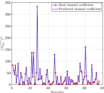
Finally, Fig.7 compares the actual and predicted values of the squared moduli of the channel coefficient h(2,3)DL between the 2-nd BS antenna and the3-rd user’s single-antenna. The nonlinear Tanh-Type massive MIMO scenario (13) of Fig. 6 was considered and the operating SNR was set to 20dB. As shown in the figure, all predicted channel values sufficiently match the actual ones.
V. CONCLUSION
A deep-learning-based method for channel calibration in generic massive MIMO systems is proposed and compared against traditional calibration methods. Unlike existing meth-ods that assume linear relationships between DL and UL channels, the proposed DNN method can operate also in non-linear setting, performing close to the Cram´er-Rao bound in the linear scenario. More importantly, it exhibits robustness in generic nonlinear scenarios even when the number of training sequences is limited. Our results indicate that deep learning-based methods can have significant potential in many param-eter estimation problems for communications, e.g., nonlinear channel estimation in massive MIMO systems.
0 20 40 60 80 100 0 50 100 150 200 250 300 350
Figure 7. Predictions of a DL channel coefficient using the proposed DNN approach for the nonlinear Tanh-Type massive MIMO scenario (13) of Fig.6 with operating SNR= 20dB.
REFERENCES
[1] J. G. Andrewset al., “What will 5G be?”IEEE J. Sel. Areas Commun., vol. 32, no. 6, pp. 1065–1082, Jun. 2014.
[2] T. L. Marzetta, “Noncooperative cellular wireless with unlimited numbers of base station antennas,”IEEE Trans. Wireless Commun., vol. 9, no. 11, pp. 3590–3600, Nov. 2010.
[3] E. G. Larsson et al., “Massive MIMO for next generation wireless systems,”IEEE Commun. Mag., vol. 52, no. 2, pp. 186–195, Feb. 2014. [4] F. Ruseket al., “Scaling up MIMO: Opportunities and challenges with very large arrays,”IEEE Signal Process. Mag., vol. 30, no. 1, pp. 40–60, Jan. 2013.
[5] L. Zheng and D. N. C. Tse, “Communication on the Grassmann manifold: A geometric approach to the noncoherent multiple-antenna channel,” IEEE Trans. Inf. Theory, vol. 48, no. 2, pp. 359–383, Feb. 2002. [6] G. Smith, ”A direct derivation of a single-antenna reciprocity relation for
the time domain,”IEEE Trans. Ant. Propag., vol. 52, no. 6, pp. 1568– 1577, Jun. 2004.
[7] F. Kaltenberger et al., “Relative channel reciprocity calibration in MIMO/TDD systems,” in Proc. IEEE FNMS, pp. 1-10, Florence, Italy, Jun. 2010.
[8] M. Petermannet al., “Multi-user pre-processing in multi-antenna OFDM TDD systems with non-reciprocal transceivers,”IEEE Trans. Commun., vol. 61, no. 9, pp. 3781–3793, Sep. 2013.
[9] X. Luo, “Robust large scale calibration for massive MIMO,” in Proc. IEEE GLOBECOM, San Diego, USA, pp.1-6, Dec. 2015.
[10] H. Wei et al., “Mutual coupling calibration for multiuser massive MIMO systems,” IEEE Trans. Wireless Commun., vol. 15, no. 1, pp. 606–619, Jan. 2016.
[11] R. Rogalinet al., “Scalable synchronization and reciprocity calibration for distributed multiuser MIMO,”IEEE Trans. Wireless Commun., vol. 13, no. 4, pp. 1815–1831, Apr. 2014.
[12] H. Papadopoulos et al., “Avalanche: Fast RF calibration of massive arrays,” inProc. IEEE GlobalSIP, pp. 607–611, Atlanta, USA, Dec. 2014. [13] J. Vieira et al., “Reciprocity calibration methods for massive MIMO based on antenna coupling,” in Proc. IEEE GLOBECOM, pp. 3708– 3712, Austin, USA, Dec. 2014.
[14] X. Luo, “Multi-user massive MIMO performance with calibration er-rors,”IEEE Trans. Wireless Commun., vol. 15, no. 7, pp. 4521–4534, Jul. 2016.
[15] W. Zhanget al., “Large-scale antenna systems with UL/DL hardware mismatch: Achievable rates analysis and calibration,”IEEE Trans. Com-mun.,vol. 63, no. 4, pp. 1216–1229, Apr. 2015.
[16] C. Shepard et al., “Argos: Practical many-antenna base stations,” in Proc. ACM Mobicom, New York, USA, pp. 53–64, Aug. 2012. [17] X. Jiang et al., “A framework for over-the-air reciprocity calibration
for TDD massive MIMO systems,”IEEE Trans. Wireless Commun.,vol. 17, no. 9, pp. 5975–5990, Sep. 2018.
[18] J. Vieiraet al., “Reciprocity calibration for massive MIMO: Proposal, modeling, and validation,” IEEE Trans. Wireless Commun., vol. 16, no. 5, pp. 3042–3056, May 2017.
[19] K. Heet al., ”Deep residual learning for image recognition,” inProc. IEEE CVPR, Las Vegas, USA, pp. 770–778, Nov. 2016.
[20] M. T. Luong et al., “Effective approaches to attention-based neural machine translation,” inProc. CEMNLP, Lisbon, Portugal, pp. 1–11, Sep. 2015.
[21] A. Graves et al., “Speech recognition with deep recurrent neural networks,” inProc. IEEE ICASSP, Vancouver, Canada, pp. 6645–6649, May 2013.
[22] D. Silveret al., “Mastering the game of Go with deep neural networks and tree search,”Nature, vol. 529, no. 7587, pp. 484–489, Jan. 2016. [23] W. Xuet al., “Improved polar decoder based on deep learning,” inProc.
IEEE SIPS, pp. 1–6, Lorient, France, Oct. 2017.
[24] L. Lugosch and W. J. Gross, “Neural offset min-sum decoding,” inProc. IEEE ISIT, pp. 1361–1365, Aachen, Germany, Jun. 2017.
[25] T. J. O’Sheaet al., “Learning to communicate: Channel auto-encoders, domain specific regularizers, and attention,” inProc. IEEE ISSPIT, pp. 223–228, Limassol, Cyprus, Dec. 2016.
[26] T. Yoo and A. Goldsmith, “Capacity and power allocation for fading mimo channel with channel estimation error,”IEEE Trans. Inf. Theory, vol. 52, no. 5, pp. 2203–2214, May 2006.
[27] A. Serra et al., “Modelling channel estimation error in lte link level simulations,” inProc. European CFSTR, pp. 8–10, Barcelona, Spain, Feb. 2012.
[28] K. Hornik et al., “Multilayer feedforward networks are universal approximators,”Neural Netw., vol. 2, no. 5, pp. 359–366, Mar. 1989. [29] D. Rumelhart et al., “Learning representations by back-propagating
errors,”Nature, vol. 323, pp. 533-536, Oct. 1986.
[30] D. Kingma and J. Ba, “Adam: A method for stochastic optimization,” [Online] https://arxiv.org/abs/1412.6980, 2014.
[31] J. Duchi et al., “Adaptive subgradient methods for online learning and stochastic optimization.”J. Machine Learning Research, vol. 12, pp. 2121-2159, Jul. 2011.