Available Online at www.ijpret.com 731
INTERNATIONAL JOURNAL OF PURE AND
APPLIED RESEARCH IN ENGINEERING AND
TECHNOLOGY
A PATH FOR HORIZING YOUR INNOVATIVE WORK
HORIZON PLANE AND COMMUNICATION DURATION FOR LOW EARTH ORBITING
(LEO) SATELLITE GROUND STATIONS
SHEETAL RAJPUT
Dept. of Computer Sci. & Engg., PRMCEAM, Amravati-444701 Accepted Date: 15/03/2016; Published Date: 01/05/2016
\
Abstract: Communication via satellite begins when the satellite is positioned in the desired
orbital position. Ground stations can communicate with LEO (Low Earth Orbiting) satellites only when the satellite is in their visibility region. The visibility region is in fact the horizon plane. Because of natural barriers or too high buildings in urban areas, practical horizon plane differs from the ideal one. The duration of the visibility and so the communication duration varies for each satellite pass at the ground station, specifically for LEO satellites which do move too fast over the Earth. This paper discusses the satellites motion detection, the difference in between ideal and practical horizon and further the variations of the communication duration between the ground station and LEO satellites. Main objective is determination of practical horizon plane and critical maximal elevation angle related to communication duration. For this paper, data recorded at the Vienna satellite ground station within the Canadian space observation project “MOST” (Micro variability and Oscillations of Stars) are applied
Keywords: LEO, satellite, ground station, horizon plane, communication duration.
.
Corresponding Author: MS. SHEETAL RAJPUT Access Online On:
www.ijpret.com
How to Cite This Article:
Sheetal Rajput, IJPRET, 2016; Volume 4 (9): 731-739
Available Online at www.ijpret.com 732 INTRODUCTION
The typical satellite communication system comprises of a ground segment, space segment and
control segment. The link which transmits radio waves from the ground station to the satellite is
called uplink. The satellite in turn transmits to the ground station by the downlink. The function of the ground segment is to receive or transmit the information to the satellite in the most reliable manner while retaining the desired signal quality. The space segment consists of one or more artificial satellites. In case of more satellites they are organized in a network called
constellation. The control segment consists of all ground facilities for control and monitoring
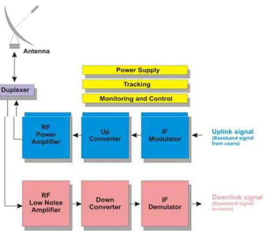
satellite. Ground stations are distinguished by their size which varies according to the volume of traffic to be carried and the type of traffic. The largest ground stations are equipped with antennas of 30 m diameter. The smallest ground stations have typically 0.6 m antennas. Some stations both transmit and receive, and some of them are receive-only (RCVO) stations. The general organization of a ground station consists of antenna subsystem with associated tracking system, transmitting and receiving equipment, monitoring system and normally power supply. Fig. 1 shows typical architecture of a ground station for both receiving and transmitting. The antenna is common to transmission and reception. The separation of the transmission and reception is achieved by means of duplexer [1].
Fig. 1. The satellite ground station architecture
Available Online at www.ijpret.com 733
ideal horizon plane is considered under 0º angles of elevation. The communication between the satellite and a ground station is established only when the satellite is visible from the ground station. For low cost LEO satellite ground stations in urban environment it will be a big challenge to ensure communication down to the horizon [2], [3]. The communication at low elevation angles can be hindered through natural barriers or too high buildings in urban areas. Misspointing is another reason of loss in communication [4]. Practical horizon differs from the ideal horizon.
This difference impacts on communication duration in between the satellite and ground stations, specifically under low elevation angles.
Thus, in order to determine the practical horizon plane and its impact on communication duration between the satellite and ground station, the general concepts of artificial satellites, orbits, tracking of satellite and ground satellite station geometry are further given. Then, data recorded at Vienna satellite ground stations are applied to determine the practical horizon plane and maximal elevation angle under which communication between the ground station and satellite rapidly fall consequently causing loss in data transfer between the source and dedication.
2 Artificial Satellites
An artificial satellite is manufactured object dedicated to continuously orbit the Earth, or other body in space. The original objectives of artificial satellites were to serve low-cost communications relays and to provide new opportunities on investigation and development of new radio techniques. Recently, especially with escalating cost of large satellites, attention is turned to smaller satellites so called microsatellites. LEO satellites have very wide applications, from remote sensing of oceans, through analyses on Earth’s climate changes, Earth’s imagery with high resolution or astronomical purposes. Ground stations have to be established in order to communicate with such satellites. Scientific missions can be accomplished in principle by only one ground station. The reason behind building more ground stations is to increase the coverage and number of measurements per observed object or area, and practically increase data download capability [2], [6], [7].
An artificial satellite essentially consists of two main functional units: payload and bus
(platform). The primary function of the payload is to provide communication by repeater and
Available Online at www.ijpret.com 734 Fig. 2. Artificial satellite [8]
Every satellite carries special instruments that enable it to perform its mission [9]. Thus, artificial satellites are classified according to their mission. There are six main types of artificial satellites, classified as follows [10]:
▪ Scientific research satellites
▪ Weather satellites
▪ Communications satellites
▪ Navigation satellites
▪ Earth observing satellites
▪ Military satellites
Scientific research satellites gather data for scientific purposes. These satellites during
performing their missions gather information about the composition and effects of the space around the Earth. Most of these satellites operate in low altitude orbits (LEO). Scientific research satellites also orbit other stars and planets. Usually, these satellites communicate with ground stations in S-band.
Weather satellites are dedicated for analyses related to weather forecast. Weather satellites
observe the atmospheric conditions over large areas. Most of these satellites operate in low altitude orbits (LEO) and in S-band. These satellites always observe the Earth at the same local time. These weather data collected under constant sunlight conditions, then can be easier compared.
Communication satellites serve as relay stations, receiving radio signals from one location and
Available Online at www.ijpret.com 735
Earth orbits (MEO & LEO). Earth observing satellites are used to map and monitor our planet’s resources and ever-changing chemical-biological life. They follow LEO orbits. [10].
Military satellites include weather, communications, navigation and Earth observing satellites
used for military purposes. The scientific research satellites, Earth observing satellites and weather satellites use low Earth orbits (LEO).
3 Orbits
The basic resources available for communication with satellites are radio frequency spectrum (RF) and orbits. The orbit is the trajectory followed by the satellite. Generally, the orbits of communication satellites are ellipses within the orbital plane defined by space orbital parameters. Orbits with zero eccentricity are called circular orbits. The movement of the satellite within its circular orbit is represented by orbital time, radius, altitude and velocity. Circular orbits are categorized based on the altitude above Earth’s surface as presented in Fig. 3.
• GEO (Geosynchronous Earth Orbits)
• MEO (Medium Earth Orbits) and
• LEO (Low Earth Orbits)
Fig. 3. Satellite orbits
4 Space Orbital Parameters
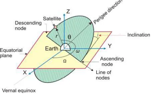
The path of the satellite’s motion is an orbit. In order to describe the satellite’s movement within its orbit in space, a few parameters are required to be defined. These are known as
space orbital parameters schematically presented in Fig. 7 and defined under below items a),
Available Online at www.ijpret.com 736 Fig. 4. Space orbital parameters
a) The position of the orbital plane in space.
This is specified by means of two parameters – the inclination i and the right ascension of the
ascending node Ω. Inclination i represents the angle of the orbital plane with respect to the
Earth’s equator. The right ascension of the ascending node Ω defines the location of the ascending and descending orbital crossing nodes with respect to a fixed direction in space. The fixed direction is Vernal equinox.
b) Location of the orbit in orbital plane.
Normally an infinite number of orbits can be laid within an orbital plane. So, the orientation of the orbit in its plane is defined by the argument of perigee ω. This is the angle, taken positively from 0º to 360º in the direction of the satellite’s motion, [1], [14], [15].
c) Position of the satellite in the orbit.
The position of the satellite in orbit is determined by the angle θ called the true anomaly, which is the angle measured positively in the direction of satellite’s movement from 0º to 360º,
d) The shape of orbit.
The shape of orbit is presented by the semi-major axis a (Fig. 4) which defines the size of orbit and the eccentricity e which defines the shape of the orbit.
5 The Horizon Plane
Available Online at www.ijpret.com 737
The inclination of a prograde orbit always lies between 0º and 90º (Fig. 4). The inclination of a retrograde orbit always lies between 90º and 180º.
Fig. 5. Orbit and ground station
6 Tracking of the Satellite
For tracking the satellite a tracking mechanism and appropriate software is used. As inputs Keplerian elements are used, calculating the actual position of
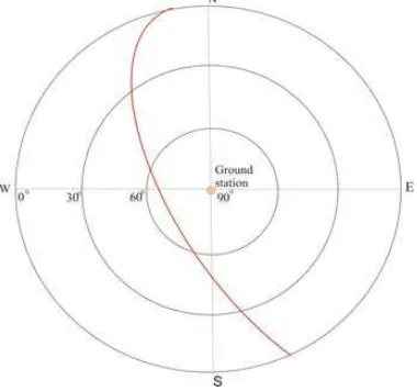
the satellite. The respective software provides real-time tracking information, usually displayed in “radar map” [2], [3]. The display mode of “radar map” includes the accurate satellite’s position with the ground station considered at the center, as in Fig. 6 presented.
Available Online at www.ijpret.com 738
The satellite’s movement (satellite’s pass) is presented with satellite’s path in radar map (red line), what in fact is the satellite’s orbit projection on the horizon plane (Fig. 8).
7 CONCLUSIONS
Motion detection enables practical horizon determination. Obviously practical horizon differs from the ideal one, for at least 2º-3º degrees of elevation in average, because of natural barriers. This is confirmed based on records at Vienna satellite ground station. Considering that for LEO satellites the contact between satellite and ground station is in range of (3-15) minutes, this difference impacts communication duration, also. During communication with LEO satellites it is obvious that at elevation angles below 10º the time efficiency falls, because of natural barriers, thus not the whole pass can be used. This leads to a decreased data flow compared to the theoretical case. The analysis of the data amount at a low elevation pass has shown that it is worth to dimension the ground station also for low elevation passes, because an important part of the stored data at the satellite can be downloaded at such passes.
REFERENCES:
1. G. Maral, M .Bousquet, SatelliteCommunications Systems, John Wiley & sons, UK, 2005. 2. S. Cakaj, K. Malaric, Rigorous analysis on performance of LEO satellite ground station in urban environment, International Journal Satellite Communications and Networking, Vol.25, No.6, 2007, pp. 619-643.
3. S. Cakaj, W. Keim, K. Malaric, Communication duration with low Earth orbiting satellites, Proc. IEEE, IASTED, 4th International Conference on Antennas, Radar and Wave Propagation, Montreal, Canada, 2007, pp. 85-88.
4. E. Alejandro at al., Control system for the antenna positioning, Proc. WSEAS, 7th International Conference on Applied Informatics and Communications, Athens, Greece, 2007, pp. 390 -392.
5. R. E. Zee, P. Stibrany, The MOST Microsatellite: A low – cost enabling technology for future space science and technology missions, Canadian Aeronautics and Space Journal, Vol. 48, No. 1, Canada, 2002, pp. 1-10.
6. W. Keim, V. Kudielka, A.L. Scholtz, A Satellite ground station for an urban environment, Proc., IASTED, International Conference on Communication Systems and Networks, Marbella, Spain, 2004, pp. 280-284.
7. M. Reyes- Ayala at al., UW Detection in TDMA satellite system, Proc. WSEAS, 6th
International Conference on Applied Informatics and Communications, Elounda, Greece, 2006, pp. 237 - 240.
Available Online at www.ijpret.com 739
9. E.A. Essex at al., monitoring the ionosphere/ plasma sphere with Low Earth Orbit satellites: The Australian microsatellite Fed Sat, Cooperative Research Center for Satellite Systems, Department of Physics, La Trobe University, Bundoora, Australia.
10. J. E. Oberright, Satellite artificial, World Book Online Reference Center, World Book, Inc 2004.
11. http://www.answers.com/topic/van-allenradiation- belt
12. N. Enescu, D. Mancas, E. Manole, Locating GPS coordinates on PDA, Proc. WSEAS, 8th
International Conference on Applied Informatics and Communications, Rhodes, Greece, 2008, pp. 470 - 474.
13. http://www.gps.gov
14. M. Richharia, Satellite Communications Systems, McGraw Hill, New York, 1999. 15. D. Roddy, Satellite communications, McGraw Hill, New York, 2006.
16. S. Cakaj, M. Fischer, A.L. Schotlz, Practical horizon plane for low Earth Orbiting (LEO) satellite ground stations, Proc. WSEAS, 9th International Conference on Applied Informatics and Communications, Istanbul, Turkey, 2009, pp. xx –xx.
17. Radio Frequency Spectrum Management Course, USTTI (United States Telecommunication Training Institute) course M6 -102, Washington DC, 2006. http://www.thetech.org/exhibits/online/satellite
18. B. Elbert, Ground Segment and Earth Station Handbook, Artech House Publishers, Boston, 2001.
19. W. Weis, W. Keim, The Austrian contribution to: Microvariabilty and Oscillation of Stars – Detection of Exoplanets, Report, Universitet Wien, Department of Astronomy, Vienna, Austria 2003.
![Fig. 2. Artificial satellite [8]](https://thumb-us.123doks.com/thumbv2/123dok_us/8712769.1741578/4.612.235.375.92.191/fig-artificial-satellite.webp)