DETAILED ANALYSIS OF AN ENDOREVERSIBLE FUEL
CELL : MAXIMUM POWER AND OPTIMAL OPERATING
TEMPERATURE DETERMINATION
Alexandre Vaudreya,∗, Philippe Baucourb, François Lanzettab, Raynal Glisesb
a
Energy Laboratory, ECAM, 40, montée Saint Barthélemy, 69 321, Lyon, France. b
Energy Department, FEMTO-ST Institute, UMR CNRS 6174, University of Franche-Comte, Parc technologique, 2, avenue Jean Moulin, 90 000 Belfort, France.
ABSTRACT
Producing electrical work in consuming chemical energy, the fuel cell (FC) is forced by the 2ndlaw to reject heat to its surrounding. However, as it
occurs for any other type of engine, this thermal energy cannot be exchanged in an isothermal way in finite time or through finite areas. As it was already done for various types of systems, including chemical engines, the fuel cell is here studied within the finite time thermodynamics framework. An endoreversible fuel cell is then defined, internally reversible but producing entropy during heat exchanges with its ambiance. Considering usual
H2/O2andH2/air chemical reactions and two different types of heat transfer laws, an optimal value of the operating temperature is highlighted, that
corresponds to a potentially maximum produced electrical power. Finally, two fundamentals results are obtained : high-temperature fuel cells could extract more useful power from the same quantity of fuel than low temperature ones, but with lower efficiencies ; thermal radiative exchanges between the fuel cell and its surrounding have to be avoided so far as possible, because of their negative effects on optimal operating temperature value. These results emphasized the importance of heat management system of such energy converters, not only for its durability but also for its performances.
Keywords:Fuel cell, efficiency, finite time thermodynamics, entropy, endoreversibility.
1. INTRODUCTION
The fuel cell (FC) is usually described as a system that directly converts into electricity the chemical energy provided by an isothermal electro-chemical process, based for example on the hydrogen/oxygen couple as fuel and combustive ; Larminie and Dicks (2003). Trying to convert into work the chemical energy carried by reactants, such system could be also viewed as a particular type of engine.
Thereby, as any other engine and according to the second law of thermodynamics, all provided chemical energy could not be converted into work and a heat quantity is always rejected by the FC to its sur-rounding. As demonstrated by Wright (2004) and later by Vaudreyet al.
(2008), the minimum thermal energy released, corresponding to the max-imum produced work, is rejected by areversible fuel cell(RFC), i.e. with no internal production of entropy. In order to include the FC into the fi-nite time thermodynamics framework, equivalence between the RFC and theCarnot heat engine(CHE) is demonstrated in the present study.
This result leads to a new definition of theendoreversible fuel cell
(EFC) and could result in the proposal of more realistic bounds and then performances criteria for FC systems. It also emphasize the strong in-fluence of the temperature difference between FC and its ambiance, and consequently of the thermal management system, on its performances.
∗
Corresponding author. Email: [email protected]
2. FINITE TIME THERMODYNAMICS
As it was highlighted by Chambadal (1957) and Novikov (1958) and later by Curzon and Ahlborn (1975), a reversible (Carnot) heat engine i.e. that have the highest thermal efficiency, can only operate in exchanging heat in an infinitely slow manner. No notable work quantity could then be produced in a limited duration process. Actually, such ideal converter cannot produce any useful power.
Indeed, energy or mass transfers during finite durations or across fi-nite areas need the existence of drops in intensive physical parameters, like e.g. temperature or chemical potential. Fourier or Fick laws are the most simple examples of such relationships betweenflux(heat transfer rate or mass flow) andforces(temperature difference or chemical poten-tial difference). Any difference in intensive parameters always leads to a production of entropy, and consequently to a decrease of whole system performances, Bejan (1997). Production of any rate of work could hence not be done without a relative lost of efficiency, regarding to the Carnot’s one, due to entropy production in exchange processes.
realistic performance criteria, regarding to operating conditions of actual systems.
A system internally reversible i.e. producing entropy only because of irreversible exchange processes with its surrounding, is usually quali-fied asendoreversible. The concept ofendoreversibility, originally pro-posed by Rubin (1979), has been successfully applied to a large scale of systems, including different types of engines, heat pumps or distillation devices. When a system is qualified asirreversible, it means that it houses both internal and external entropy productions.
3. FUEL CELLS AND CHEMICAL ENGINES
Finite time thermodynamics have been previously applied to the study of chemical engines and fuel cell (FC) models. A Carnot heat engine fed by an exothermic chemical process in a flow reactor was studied by On-drechenet al.(1980b). Authors analyzed the influence of limited dwell time and rate of reaction on the produced mechanical power. For dif-ferent orders or reaction, they highlighted the existence of maximum re-sulting mechanical power reactants feeding rates. Later, they extended the same idea to temperature dependant reaction rates phenomena, On-drechenet al.(1980a). De Vos (1991) considered the same type of sys-tem but in a slightly different way. He proposed to extend to matter the heat resistance and reservoir concepts of the Curzon and Ahlborn heat engine (CAHE). Whereas efficiency of the CAHE is limited by the rate at which heat can be transfered from the working fluid to heat reservoirs, the one of a chemical engine is similarly limited by the rate at which matter can be transfered from chemical reactants flow to reaction sites. Temper-ature difference between heat reservoirs in the CAHE is then replaced by a chemical potential difference. The author analyzed the impact of both temperature and chemical potential differences on the energy converter optimal performances, but with linear mass transfer laws. The simpler case of an isothermal chemical engine, i.e. with only a chemical potential difference, fed by linear mass transfer laws have been analyzed by Chen
et al.(1997b). As some authors did for heat transfer laws, De Vos (1985), other types of mass transfer laws have later been tested by Gordon (1993) and Gordon and Orlov (1993) for an isothermal chemical engine. Later, the effect of a possiblemass leakwithin the system was considered by Chenet al.(1998).
The specific case of FC, including electrochemical phenomena, was treated more lately by Sieniutycz (2010, 2011). Author introduced elec-trochemical potentials(instead of chemical ones) andoverpotential phe-nomenon in a model similar to the one of De Vos (1991) previously quoted. Unfortunately, the interesting formalism proposed in this stud-ies have not been applied to practical case of FC systems, including for example an hydrogen/oxygen reaction, or the typical operating tempera-ture range of a specific FC technology.
More complex FC system configurations, including combined cy-cles with heat engines, have been studied by Chenet al.(1997a); Zhao and Chen (2009); Zhang and Chen (2010, 2011). However, in all these studies, FC is always considered only as a system producing both elec-tricity and heat, the latter being used to feed classical endoreversible heat engines. Finite time thermodynamics is then applied only to the com-bined cycle heat engine and not to the fuel cell.
Some other FC particular topics were also concerned by a finite time thermodynamical analysis, like current path within the feeding ducts in Watowich and Berry (1986); Vargas and Bejan (2004) or design of the thermal management system in Sharifian and Saidi (2005). Nevertheless, none of these previous studies took into account neither a particular and practical chemical reaction used in real fuel cells nor the specific parame-ters ranges of different FC technologies, like e.g. high or low temperature systems.
4. REVERSIBLE FUEL CELL AND CARNOT HEAT ENGINE
Let us consider an open and steady state system, similar to a fuel cell i.e. operating at constant temperatureT and pressurepand housing the followed exothermic chemical reaction :
X
j∈R
νj·Aj→X k∈P
νk·Ak (1)
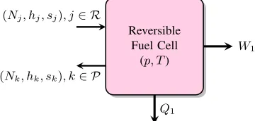
withAithe chemical species andνitheir corresponding stoichiometric coefficients. RandPare respectively the groups of reactants and prod-ucts of previous reaction, both considered as ideal gases. Besides molar quantities of reactants and products, it is assumed that the whole sys-tem exchanges workW1 and heatQ1with its surrounding. Considered
Reversible Fuel Cell
(p, T)
W1
Q1 (Nj, hj, sj), j∈ R
(Nk, hk, sk), k∈ P
Fig. 1Schematic diagram of system 1 : an isothermal and isobaric open system operating in steady state at pressurepand temperatureT, producing workW1and heatQ1 while consuming chemical reac-tantsNjand rejecting chemical productsNk.
system is drawn on Fig. 1 and noted1in the rest. It directly converts into work the chemical energy provided by reaction (1). Its energy and entropy balances are respectively :
δW1 =−∆h(T)·dξ−δQ1 (2)
δiS1 = ∆s(p, T)·dξ+δQ1T (3)
with ∆h and ∆s the variations of molar enthalpy and molar entropy through reaction (1), δQ1 the exchanged heat quantity,δiS1 the
inter-nal production of entropy, pthe vector of the partial pressures of both reactants and products andξthe reaction progress coordinate defined by :
dξ=
−dNj νj
j∈R =
dNk νk
k∈P
(4)
Combining (2) and (3), the variation of produced work can be expressed as :
δW1=−∆g(p, T)·dξ−T·δiS1 (5)
with∆gthe variation of the Gibbs energygfor chemical process (1). Logically, the maximum value of workδW1 will be produced by a
re-versible system, i.e. with no internal production of entropy (δiS1= 0) :
δW1,max=δW1,max=δW1,rev=−∆g(p, T)·dξ (6)
Dividing this provided work by the reaction progress results on the molar reversible workwrevinJ/mol, defined as :
w1,rev=
δW1,rev
dξ =−∆g(p, T) (7)
that corresponds to the quantity of useful energy provided by reversible system1for one mole of consumed chemical reactants. The energy ef-ficiency ηwill be defined as the fraction of useful energyw1 on
con-sumed energy. For the considered reversible system, Larminie and Dicks (2003) :
η1,rev=
w1
−∆h(T) =
∆g(p, T)
∆h(T) (8)
Zhaoet al.(2008). The well known polarization curve i.e. the voltage vs. current produced by the FC should then be replaced by a constant value of voltageE inV, equal to the “reversible” one, Larminie and Dicks (2003) :
Erev=−
∆g(p, T)
ne·F (9)
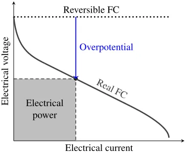
Fis the Faraday constant andnethe number of electrons exchanged by each molecule of fuel (2in the hydrogen/oxygen reaction (21)). Exam-ples of such curves are drawn on Fig. 2.
•
Electrical power
Electrical current
Electrical
v
oltage
Real FC Reversible FC
Overpotential
Fig. 2Schematic polarization curve (voltage vs. current) of a real and a reversible fuel cell (RFC). Contrary to the real one, the RFC have an electrical potentialEindependent on the current value. Eonly depends on both operating temperature and partial pressures of chemical reactants and products, as highlighted by relation (9).
Let us consider now an other system, noted2and drawn on Fig. 3, that produces only heat from the same chemical reaction (1), and used as a hot source of a Carnot heat engine (CHE). First and second laws applied to this combustion system gives :
0 =−∆h(T)·dξ−δQ2 (10)
δiS2 = ∆s(p, T)·dξ+δQT∗2 (11)
withT∗the corresponding temperature of chemical process. Supposing it reversible (δiS2= 0) and combining (10) and (11), the theoretical
tem-peratureT∗arises, sometimes calledentropic temperatureas by Laouir
et al.(2001) orequilibrium temperatureby De Groot (2004) :
T∗(p, T) = ∆h(T)
∆s(p, T) (12)
. .
T∗
. Q2 .
(Nj, hj, sj), j∈ R
.
(Nk, hk, sk), k∈ P
.
CHE .W2,rev
. Q
. T
Fig. 3Schematic diagram of system 2 : a flow reactor housing the same exothermic chemical process as system 1 (Fig. 1) but occurring at equilibrium temperatureT∗and producing only heat quantityQ
2. Reactor is used at heat source of a Carnot heat engine (CHE) that produces workW2,revand rejecting heatQto heat sink at
temper-atureT.
As explained by Lutzet al.(2002); Ro and Sohn (2007), this idealized temperature corresponds to the one reached by a combustion process as (1) that both consumes and rejects reactants and products at temperature
T. It is very important to notice the difference betweenequilibrium tem-peratureT∗and the usualadiabatic flame temperatureTad. The latter
is the temperature reached by an adiabatic combustion process, i.e. if the whole enthalpy variation is used to heat up the reaction, see Bejan (1997). At the contrary, combustion phenomenon in system2is not adiabatic, it continuously exchanges heat of reaction with combined heat engine. TemperatureT∗is reached in using heat contained in chemical products and rejected during their cooling fromT∗toT, to heat up reactants from
T toT∗.
A Carnot heat engine (CHE) operating between temperaturesT and
T∗in consuming heatδQ2, provided by previous ideal combustion
sys-tem, can produce a work quantity Wright (2004); Vaudreyet al.(2008) :
δW2,rev = δQ2·η2=δQ2·
1− T T∗(p, T)
= −∆h(T)
| {z } =q∗
·dξ·
1−T·∆s(p, T) ∆h(T)
= −∆g(p, T)·dξ (13) It can be seen that in relations (6) and (13) thatw1,rev=w2,rev.
Conse-quently,η1,rev=η2,rev. This leads to conclude on the thermodynamical
equivalence of both reversible systems, i.e. of RFC and CHE. Indeed, system2is defined as a burner (housing an exothermic chemical reac-tion) associated to a Carnot engine that producing work. Efficiencyη2
of the whole system is the one of a classical ideal heat engine. It is im-portant here to notice that temperatureT∗is not really considered as an actual physical temperature but more as a mathematical way to express a chemical engine efficiency in the same form1−Tcold
Thot as for heat engine,
as highlighted by Eq.(13).
Hence, a reversible fuel cell could be considered as a Carnot heat engine operating with a heat source at equilibrium temperatureT∗and a cold sink at its own temperatureT(see Fig. 3).
5. ENDOREVERSIBLE FUEL CELL
As originally demonstrated by Chambadal (1957) and Novikov (1958), an entirely reversible engine can exchange thermal energies only in in-finitely slowly processes and finally can not produce any useful power. Heat transfer can not occur across finite exchange areas in an isothermal way and a finite difference of temperature is necessary to allow rejection of produced heat. On Fig. 4, the FC operates at temperatureT in an am-biance at the cold temperature notedTc< T. DifferenceT−Tcbetween the FC operating temperature and the surrounding one vary with the spe-cific FC technology. It is weak for low temperature systems like PEMFC and could be very important for high temperature systems such as SOFC. Rejected molar heat quantityq=δQ/dξinJ/molis now a function of temperaturesTandTc, see Fig. 4. De Vos (1985) showed that different heat transfer laws could be applied to this system. Present study will consider the general heat transfer law as :
q(T, Tc) =kn·(Tn−Tcn) (14)
wherekis equivalent to a thermal conductance (usually defined as a prod-uct of heat transfer coefficient and heat transfer area), but divided by re-action progress as previously did for molar work of Eq.(7) and lately for molar heat rejectedq. nis an integer representative of the type of heat transfer law. Then, the heat exchange process will be called linear as with usual thermal convection ifn= 1, and nonlinear ifn >1.
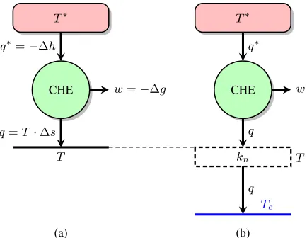
The equivalent heat engine of Fig. 4 operating betweenT andT∗
and being internally reversible (i.e. endoreversible), its molar entropy balance is :
q∗(T) T∗(p, T) =
q(T, Tc)
T∗
q∗=−∆h
CHE w=−∆g
q=T·∆s
T
T∗
q∗
CHE w
q
kn T
q
Tc
(a) (b)
Fig. 4Equivalent heat engines of (a) reversible fuel cell (RFC) and (b) endoreversible fuel cells (EFC).
withq∗(T) = −∆h(T) the heat delivered by an equivalent hot heat source (Fig. 3). Combining (13), (14) and (15), the molar work becomes :
w = q∗(T)·
1− T T∗(p, T)
=q(T, Tc)·
T∗(p, T) T −1
= kn·(Tn−Tcn)·
T∗(p, T) T −1
(16) and explicitly depends on temperaturesT andTc. Otherwise, related energy efficiency is :
η= w q∗ = 1−
T
T∗(p, T) =η1,rev (17)
Let us now suppose that operating temperatureT could vary from the environment oneTc to T∗. Considering expression (16) of the molar workw, three cases have to be considered :
1. IfT = Tc, according to equation (14), no heat quantity can be exchanged and thenq=T·∆s= 0(see Fig. 4). Therefore, molar variation of entropy∆sis null and chemical process can not occur. The whole system can not produce any useful work andw= 0. 2. IfT increases, it can reach its maximum value, notedTmax, that
corresponds to an equality between the operating temperature and the entropic one, i.e. root of the following function :
f(T) =T−T∗(p, T) = 0⇒Tmax (18)
This situation leads to the vanishing of Gibbs energy variation :
−∆g(p, Tmax) = 0 (19)
and tow= 0, according to (7).
3. IfTc< T < Tmax, the workwis a continuous and positive
func-tion ofT which could be maximized.
Unlike other endoreversible engines, that are usually supposed to operate with independent values of hot and cold temperatures, Eq.(16) (i.e. the molar produced work) depicts a non linear link between entropic and op-erating temperatures,T∗andT. This situation corresponds to an equiva-lent heat engine whose value of the hot source temperature is a function of the cold sink one. Consequently, the maximum power corresponding temperature could not be given as the usual geometric mean of high and low temperatures√Tc·Tmax, see Bejan (1996). The optimal
tempera-tureTbcorresponds to a maximum value ofw: b
T = arg max
T (w(T)) (20)
This relationship will be optimized by a Newton numerical algorithm us-ing√Tc·Tmaxas an initial point which turns out to be a satisfying
ap-proximation (see Fig. 7).
6. HYDROGEN FUEL CELL
As a practical example, let us consider the case of an endoreversible fuel cell (EFC) operating in consuming hydrogen as fuel. Chemical reaction (1) is :
H2+ 1/2·O2→H2O (21)
The surrounding temperature is fixed for example at Tc = 298,15 K. Thanks to experimental correlations published by Chase (2000),
evolu-Fig. 5Entropic temperatureT∗of Eq.(12) regarding to the fuel cell (FC) operating oneT for pureO2as combustive (xO2= 1).Tmaxis the
maximum value of operating temperatureT and is reached when
T =T∗(p, T).
tion of the entropic temperatureT∗vs. reduced temperatureθfor pure oxygen as combustive have been represented on Fig. 5:
θ= T−Tc Tmax−Tc
(22) Dot at the end of curve represents the maximum temperature, correspond-ing toθ = 1⇒T∗=T =Tmax. Maximum temperature for pureO2
isTmax(xO2= 1)'4 310 K. Using air as combustive leads to a similar
curve, but withTmax(xO2= 0,21)'3 884 K.
Using Eqs.(8) and (17), respective energy efficiencies for pure oxy-gen and air as combustive are represented on Fig. 6, with values of coor-dinateθbased on maximum temperature with pure oxygenTmax(xO2= 1). It can be observed on Fig. 6 a quasi linear decrease ofηwith the operating temperatureT, leading to a zero value forT =Tmax(see
rela-tion (19)). Energy efficiency corresponding to air consumprela-tion reach zero at is own value ofTmax, less than the one of pure oxygen, as presented
on the right part of figure 6.
Range ofθvalues does not start at zero because of the possible liquid water formation that can occur below100◦C. Hence, below this temper-ature, it is extremely difficult to know whether the produced water is in liquid or vapor phase. Values of enthalpy variation∆hand then of en-ergy efficiency (8) being strongly different if water is in gaseous or liquid phase, this specific temperature range have not been treated.
6.1. Linear heat transfer law
Considering the molar work (16) produced with linear transfer law (n= 1) as for example with a heat convection phenomenon, it can be given by :
w=k1·(T∗(p, T)−T)·
1−Tc T
Fig. 6Energy efficienciesηof RFC (Eqs.(8) and (17)) fed by pureO2(full line) and air (dashed line) as combustive. ηvanish in both cases for respective values ofTmax.
Fig. 7Reduced molar workw/wbvs. θwith the finite conductance (14)
for RFC and for an endoreversible heat engine (EHE) operating between constants temperaturesTcandTmax.
are drawn on Fig. 7. Evolution of reduced workw/wbvs. reduced op-erating temperatureθof Eq.(22) is drawn in continuous line (curve1).
b
wis the maximum value ofwregarding to temperatureT. The second dashed line (curve2), corresponds to the case where hot temperature is supposed to be constant and equal to the highest operating oneTmaxand
where expression of the molar workw00corresponds to those of an usual endoreversible heat engine (EHE) :
w00=k1·(Tmax−T)·
1−Tc T
(24)
In fact, this engine is the one represented on Fig. 4b, but in replacing variable high temperatureT∗by the constant oneTmax. In this particular
case, it is easy to show that, Chambadal (1957) :
∂w00 ∂T =k1·
Tc·Tmax
T2 −1
= 0⇒Tb=
√
Tc·Tmax (25)
and the optimal operating temperatureTbalso leads to a maximum work :
b
w=k1· √
Tmax−
√ Tc
2
(26)
and to the famous form related energy efficiency :
b
η= 1− Tb Tmax
= 1−
r
Tc Tmax
(27)
ˆ
ηis the energy efficiency of EHE operating betweenTcandTmaxwhen
produced work is maximum. Difference between curves 1and 2is a direct consequence of nonlinear link between the entropic temperature
T∗and the operating oneT, see relation (12). Therefore, the value of the optimal temperatureTbcorresponding tow=wbis slightly modified and
actually different from those obtained by a geometric mean (25) of both high and low temperatures. Main results are presented in Table 1 for an hydrogen/air chemical reaction.
Table 1Maximum power operating temperatureTband related energy
ef-ficiencyηbfor variable and constant equivalent high temperatures.
Concerned chemical process involve air as combustive.
High temperature T∗(p, T) Tmax b
T 992 K 1 076 K
b
η 75,3% 72,3%
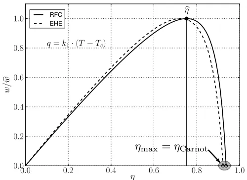
The well used curvew/wb=f(η)is drawn on Fig. 8 for each en-doreversible system. Difference between curves, due to nonlinearity of
Fig. 8Reduced molar workw/wbregarding to energy efficiencyη for an
EFC and for an EHE operating betweenTcandTmax. Maximum i.e. Carnot values of efficiencies, corresponding to thermal equilib-rium between converters and ambiance (T =Tc) and then to no
work produced, are highlighted on the right of horizontal axis.
T∗=f(T)is here more significant, and leads to different values of max-imum (Carnot) efficiencies, emphasized on the right part of efficiencies axis.
This first result is interesting but does not take into account the dif-ference of heat transfer types between low and high-temperature systems. Hence, high temperature heat transfer processes are often driven by radia-tive effects.
6.2. Nonlinear heat transfer law
the specific effect of radiative exchange on performances. Produced mo-lar work can be expressed as :
w=k4·(T4−Tc4)·
T∗(p, T) T −1
(28)
As presented on Fig. 9 (full line), the nonlinear heat exchange law leads to a strong increase of the optimal temperature :Tb'2 910 Kin the same
chemical conditions as previously. This result could be explained by the
Fig. 9Evolutions of reduced molar workw/wbvs.θforn= 4(continuous
curve) andn= 1(dashed curve).
fact that the same heat quantity needs a higher value of the temperature difference to be exchanged by a radiative way than thanks to convective phenomenon. The molar heatqcorresponding to a maximum produced work could be only released beyond a temperature difference higher with radiative exchange than with only a convective one. To make the dif-ference with previous linear case, we have drawn on the same graph the molar work corresponding to the linear heat transfer law (dashed line).
Efficiency-work curves of both linear and nonlinear heat transfer laws are presented on Fig. 10. Simultaneously to the increase of the
max-Fig. 10Evolutions of reduced molar workw/wbregarding to energy
effi-ciencyηwithn= 4(full line) andn= 1(dashed line). For any type of heat transfer law, minimum operating temperatureT =Tc
corresponds to maximum efficiencyη=ηmaxand tow= 0.
imum work operating temperature, it appears a strong decrease of related
energy efficiency :ηb'25%. As presented on Fig. 9, an increase of the operating temperature corresponds to a decrease of its efficiency. Hence, the radiative heat transfer process appears to be unfavourable regarding to EFC performances because it moves up the optimal operating temper-ature from those corresponding to convective heat exchange phenomena. Finally, a relevant thermal management system design for high tempera-ture FC will have to minimize radiative losses effects in order to decrease as much as possible the corresponding optimal temperature. The closer it is from operating temperature and the better are potential performances of the system.
6.3. Consequences on different fuel cell technologies
Previous curves are useful for making the difference between low and high-temperatures fuel cells. Typical range of operating temperatures of protons exchange membrane fuel cells (PEMFC), i.e. 60◦C ≤ T ≤ 120◦Cis drawn on the left of figure 11. As previously presented on
Fig. 11Reduced molar work and efficiency of different types of FC for air as combustive. Low temperature FC as e.g. PEM are characterized by high values of energy efficiencyηbut low values of produced work
w. At the contrary for high temperature FC as e.g. SOFC, produced work is potentially high but balanced by a lower efficiency.
Fig. 6, a low temperature hydrogen fuel cell is characterized by high value of its energy efficiencyη. On a first hand, its low temperature difference with surrounding prevents to reject large heat quantityq, and according to the Carnot principle, to produce large work quantityw, as presented on Fig. 11.
On a second hand, high-temperature fuel cells, such as solid oxide ones (SOFC), can easily evacuate generated heat quantities, because of their high temperature differences with the ambiance, and are also able to produce large quantities of useful work. On the right part of Fig. 11 is also drawn the typical operating temperature range of SOFC, i.e. 700◦C≤ T ≤ 1 000◦C. However, this advantage is counterbalanced by a lower energy efficiency, as shown on right part of Fig. 6.
Nevertheless, operating temperatureTˆthat corresponds to a maxi-mum amount of work produced is even so within the temperature range of actual SOFC.
7. CONCLUSIONS
any other type of energy converter, the finite time thermodynamics study of FC :
• provide more realistic bounds of performances, regarding to those of actual systems.
• allow to look for optimal operating conditions, corresponding for example to a maximum work produced.
Then, maximization of the produced electrical work regarding to the fuel cell operating temperature has led to highlight an optimal configuration, numerically calculated for an hydrogen/air reaction for standard condi-tions of pressure. If only exchanging heat with surrounding via convec-tion process, such hydrogen fuel cell could potentially produce a maxi-mum amount of useful power if operating at temperatureTˆ'992 K = 719◦C. In that case, corresponding energy efficiency is about75%. This result is important because obtained optimal temperature is within the operating temperature range of actual solid oxide fuel cells.
However, existence of an other heat transfer process, as e.g. a radia-tive one, could modify the corresponding value of optimal temperature. In a pure radiative heat exchange configuration, our results show that the latter dramatically increase, far over the operating temperature range of any existing fuel cell technology. Moreover, corresponding efficiency drop to about25%.
These results leads to conclude on the necessity for a relevant ther-mal management system to avoid radiative therther-mal effects as far as possi-ble and to favour the convective heat exchange phenomena, for example in adapting design of heat management ancillary systems. An efficient thermal management system will be able to evacuate the heat generated while maintaining operating temperature of the FC close to the optimal one previously highlighted.
The present endoreversible fuel cell is based on an only one thermal finite conductance due to the heat transfer rate exchange with the am-biance. It would be significant to also consider a non reversible chemical reaction, using for example the results of chemical thermodynamics in finite time Andresenet al.(1984), or a finite time electrochemistry Wa-towich and Berry (1986). In the same way, different types of internal entropy production could be progressively taken into account.
Moreover, design and optimization processes of fuel cell systems have also to take into account the fundamental Carnot principles. The heat rate rejected from the system to the surrounding is fundamental and strongly influences at least the electrical power produced.
NOMENCLATURE
A chemical species
E electrical potential (V)
F Faraday constant (C/mol)
g molar Gibbs energy (J/mol)
h molar enthalpy (J/mol)
k molar thermal conductance (J/(mol·K))
N amount of substance (mol)
p pressure (Pa)
P groups of products of a chemical reaction
q molar heat (J/mol)
Q heat or thermal energy (J)
R groups of reactants of a chemical reaction
s molar entropy (J/(mol·K))
S entropy (J/K)
T temperature (K)
w molar work (J/mol)
W work or useful energy (J)
Greek Symbols
∆ variation of a molar quantity through a chemical reaction
η energy efficiency
ν stoichiometric coefficient
ξ reaction progress (mol)
Superscripts
* equilibrium phenomenon
Subscripts
c cold temperature i internal production rev reversible phenomenon
Acronyms
CAHE Curzon and Ahlborn Heat Engine model CHE Carnot Heat Engine
EFC Endoreversible Fuel Cell FC Fuel Cell
RFC Reversible Fuel Cell
REFERENCES
Andresen, B., Berry, R.S., Ondrechen, M.J., and Salamon, P., 1984, “Thermodynamics for Processes in Finite Time,”Accounts of Chemical Research,17, 266–271,
http://dx.doi.org/10.1021/ar00104a001.
Bejan, A., 1996, “Entropy generation minimization : The new thermo-dynamics of finite-size devices and finite-time processes,”Journal of Ap-plied Physics,79(3), 1191–1218,
http://dx.doi.org/10.1063/1.362674.
Bejan, A., 1997,Advanced Engineering Thermodynamics, Wiley, New York.
Chambadal, P., 1957,Les centrales nucléaires, A. Colin, Paris.
Chase, M.W., 2000,NIST-JANAF Thermochemical Tables, American In-stitute of Physics.
Chen, L., and Sun, F., 2004,Advances in Finite Time Thermodynamics : Analysis and Optimization, Nova Science Publishers.
Chen, L., Sun, F., and Wu, C., 1998, “Performance of chemical engines with a mass leak,”Journal of Physics D: Applied Physics,31, 1595,
http://dx.doi.org/10.1088/0022-3727/31/13/014.
Chen, L., Sun, F., Wu, C., and Gong, J., 1997a, “Maximum Power of a Combined-Cycle Isothermal Chemical Engine,”Applied Thermal Engi-neering,17(7), 629–637,
http://dx.doi.org/10.1016/S1359-4311(96)00082-8.
Chen, L., Sun, F., Wu, C., and Yu, J., 1997b, “Performance characteristic of isothermal chemical engines,” Energy conversion and management,
38(18), 1841–1846,
http://dx.doi.org/10.1016/S0196-8904(96)00120-3.
Curzon, F.L., and Ahlborn, B., 1975, “Efficiency of a Carnot Engine at Maximum Power Output,”American Journal of Physics,43, 22–24,
http://dx.doi.org/10.1119/1.10023.
De Groot, A., 2004,Advanced exergy analysis of high temperature fuel cell systems, Ph.D. thesis, Delft University of Technology, Delft, Nether-lands.
De Vos, A., 1985, “Efficiency of some heat engines at maximum-power conditions,”American Journal of Physics,53(6), 570–573,
http://dx.doi.org/10.1119/1.14240.
De Vos, A., 1991, “Endoreversible Thermodynamics and Chemical Re-actions,”Journal of Physical Chemistry,95(11), 4534–4540,
Gordon, J.M., 1993, “Maximum work from isothermal chemical en-gines,”Journal of applied physics,73(1), 8–11,
http://dx.doi.org/10.1063/1.353835.
Gordon, J.M., and Orlov, V.N., 1993, “Performance characteristics of en-doreversible chemical engines,”Journal of applied physics,74(9), 5303– 5309,
http://dx.doi.org/10.1063/1.354253.
Laouir, A., Le Goff, P., and Hornut, J.M., 2001, “A model mechanism for assessment of exergy: analogic with the balance of a lever,”International Journal of Thermal Sciences,40, 659–668,
http://dx.doi.org/10.1016/S1290-0729(01)01255-8.
Larminie, J., and Dicks, A., 2003,Fuel Cell Systems Explained, Wiley. Lutz, A.E., Larson, R.S., and Keller, J.O., 2002, “Thermodynamic com-parison of fuel cells to the Carnot cycle,”International Journal of Hydro-gen Energy,27, 1103–1111,
http://dx.doi.org/10.1016/S0360-3199(02)00016-2.
Novikov, I.J., 1958, “The efficiency ot atomic power stations,”J Nuclear Energy,7(2), 125–128.
Ondrechen, M.J., Andresen, B., and Berry, R.S., 1980a, “Thermodynam-ics in finite time : Processes with temperature-dependent chemical reac-tions,”Journal of Chemical Physics,73(11), 5838–5843,
http://dx.doi.org/10.1063/1.440026.
Ondrechen, M.J., Berry, R.S., and Andresen, B., 1980b, “Thermodynam-ics in finite time : A chemically driven engine,” Journal of Chemical Physics,72(9), 5118–5124,
http://dx.doi.org/10.1063/1.439744.
Ro, S.T., and Sohn, J.J., 2007, “Some issues on performance analysis of fuel cells in thermodynamic point of view,”Journal of Power Sources,
167, 295–301,
http://dx.doi.org/10.1016/j.jpowsour.2007.02.073.
Rubin, M.H., 1979, “Optimal configuration of a class of irreversible heat engines. I,”Physical Review A,19(3), 1272–1276.
Sharifian, L., and Saidi, M.H., 2005, “Optimization of the PEM Fuel Cell Cooling System by Entropy Generation Minimization,”3rd International Conference on Fuel Cell Science, Engineering and Technology, ASME, Ypsilanti, Michigan, USA,
http://dx.doi.org/10.1115/FUELCELL2005-74124.
Sieniutycz, S., 2010, “Finite-rate thermodynamics of power production in thermal, chemical and electrochemical systems,”International Journal of Heat and Mass Transfer,53(13), 2864–2876,
http://dx.doi.org/10.1016/j.ijheatmasstransfer.2010.02.009.
Sieniutycz, S., 2011, “Identification and selection of unconstrained con-trols in power systems,”International Journal of Heat and Mass Transfer,
54(4), 938–948,
http://dx.doi.org/10.1016/j.ijheatmasstransfer.2010.10.009.
Sieniutycz, S., and Jezowski, J., 2009,Energy Optimization in Process Systems, Elsevier.
Vargas, J.C.V., and Bejan, A., 2004, “Thermodynamic optimization of in-ternal structure in a fuel cell,”International Journal of Energy Research,
28, 319–339,
http://dx.doi.org/10.1002/er.967.
Vaudrey, A., Baucour, P., Lanzetta, F., and Glises, R., 2008, “Finite time analysis of an endoreversible fuel cell,”Fundamentals and Developments of Fuel Cell Conference, Nancy, France.
Watowich, S.J., and Berry, R.S., 1986, “Optimal Current Paths for Model Electrochemical Systems,” Journal of Physical Chemistry, 90, 4624– 4631,
http://dx.doi.org/10.1021/j100410a031.
Wright, S.E., 2004, “Comparison of the theoretical performance potential of fuel cells and heat engines,”Renewable Energy,29(2), 179–195,
http://dx.doi.org/10.1016/S0960-1481(03)00191-5.
Wu, C., Chen, L., and Chen, J., 1999,Recent Advances in Finite Time Thermodynamics, Nova Science Publishers.
Zhang, X., and Chen, J., 2010, “Performance analysis and parametric optimum criteria of a class of irreversible fuel cell/heat engine hybrid systems,”International Journal of Hydrogen Energy,35(1), 284–293,
http://dx.doi.org/10.1016/j.ijhydene.2009.09.093.
Zhang, X., and Chen, J., 2011, “Maximum equivalent power output and performance optimization analysis of an alkaline fuel cell/heat-driven cy-cle hybrid system,”Journal of Power Sources,196, 10088–10093,
http://dx.doi.org/10.1016/j.jpowsour.2011.08.001.
Zhao, Y., and Chen, J., 2009, “Modeling and optimization of a typical fuel cell-heat engine hybrid system and its parametric design criteria,”
Journal of Power Sources,186, 96–103,
http://dx.doi.org/10.1016/j.jpowsour.2008.09.083.
Zhao, Y., Ou, C., and Chen, J., 2008, “A new analytical approach to model and evaluate the performance of a class of irreversible fuel cells,” Inter-national Journal of Hydrogen Energy,33(15), 4161–4170,