Copyright © 2013 IJECCE, All right reserved
Simulation of DA DCT Using ECAT for Reducing the
Truncation Errors
K. V. S. P. Pravallika
Abstract — Discrete cosine transform (DCT) is widely used
in image and video compression applications. The paper mainly deals with implementation of image compression application based on Distributed Arithmetic (DA) DCT using Error Compensated Adder Tree (ECAT) and simulating it to achieve low error rate. Distributed Arithmetic (DA) based Error Compensated Adder Tree (ECAT) is operates shifting and addition in parallel instead of using multipliers where the complexity is reduced. The proposed architecture deals with 9 bit input and 12 bit output where it meets the Peak Signal to Noise Ratio (PSNR) requirements. Advantages of ECAT based DA-DCT are low error rate and improved speed in image and video compression applications. The project is implemented in Verilog HDL language and simulated in ModelSim XE III 6.4b. The project synthesis is done using Xilinx ISE 10.1. The results obtained were evaluated with the help of MATLAB.
Keywords — Distributed Arithmetic (DA), Error
Compensated Adder Tree (ECAT), Discrete Cosine Transform (DCT), Peak Signal to Noise Ratio (PSNR).
I.
I
NTRODUCTIONDiscrete Cosine Transform (DCT) is widely used tool in image an video compression applications [1]. The multiplier-based DCTs were presented and implemented in [2] and [3].To reduce area, ROM-based distributed arithmetic (DA) was applied in DCT cores [4]–[6]. Uramoto et al [4] implemented the DA-based multipliers using ROMs to produce partial products together with adders that accumulated these partial products. In this way, instead of multipliers, the DA-based ROM can be applied in a DCT core design to reduce the area required. In addition, the symmetrical properties of the DCT transform and parallel DA architecture can be used in reducing the ROM size in [5] and [6], respectively. Recently, ROM-free DA architectures were presented [7]– [11]. Shams et al. employed a bit-level sharing scheme to construct the adder-based butterfly matrix called new DA (NEDA) [7]. Being compressed, the butterfly-adder-matrix in [7] utilized 35 adders and 8 shift-addition elements to replace the ROM. Based on NEDA architecture, the recursive form and arithmetic logic unit (ALU) were applied in DCT design to reduce area cost [8], [9]. Hence the NEDA architecture is the smallest architecture for DA-based DCT core designs, but speed limitations exist in the operations of serial shifting and addition after the DA-computation. The high-throughput shift-adder-tree (SAT) and adder-tree (AT), those unroll the number of shifting and addition words in parallel for DA-based computation, were introduced in [10] and [11], respectively. However, a large truncation error occurred. In order to reduce the truncation error effect, several error compensation bias methods have been presented [12]–[14] based on statistical
analysis of the relationship between partial products and multiplier-multiplicand. DA-based DCT core with an error-compensated adder-tree (ECAT) was proposed in [15]. ECAT operates shifting and addition in parallel by unrolling all the words required to be computed. Furthermore, the error-compensated circuit alleviates the truncation error for high accuracy design.
This paper uses this ECAT architecture to design 2D-DCT core and simulate it to demonstrate 2D-DCT based image compression. The ECAT (p,q) is chosen to be (12,9) to achieve more precision and less truncation errors.
II.
D
ISTRIBUTEDA
RITHMETICB
ASEDD
ISCRETEC
OSINET
RANSFORMDistributed Arithmetic (DA) plays a key role in embedding DSP functions in FPGA devices. Distributed Arithmetic performs multiplication with look-up table based schemes. DA specifically targets the sum of products (sometimes referred to as the vector dot product) computation that covers many of the important DSP filtering and frequency transforming functions. The derivation of the DA algorithm is extremely simple but its applications are extremely broad. The mathematics includes a mix of Boolean and ordinary algebra and requires no prior preparation - even for the logic designer. In DA the task of summing product terms is replaced by table look-up procedures that are easily implemented in the configurable logic block (CLB) look-up table architecture. The arithmetic operations are reduced to addition, subtraction, and binary scaling. With scaling by negative powers of 2, the actual implementation entails the shifting of binary coded data words toward the least significant bit and the use of sign extension bits to maintain the sign at its normal bit position.
Discrete Cosine Transform (DCT)
The forward and inverse 2-D DCT can be written as shown in equation 1 and 2 below
𝑧 𝑥, 𝑦 =2
𝑁𝐶 𝑥 𝐶(𝑦) 𝑥 𝑖, 𝑗 𝑐𝑜𝑠
2𝑖 + 1 𝑥𝜋 2𝑁 𝑁−1
𝑗 =0 𝑁−1
𝑖 =0
𝑐𝑜𝑠 2𝑗 + 1 𝑦𝜋 2𝑁
(1)
𝑥 𝑖, 𝑗 =2
𝑁 𝐶 𝑥 𝑐 𝑦 𝑍(𝑥, 𝑦)𝑐𝑜𝑠
2𝑖 + 1 𝑥𝜋 2𝑁 𝑁−1
𝑦=0 𝑁−1
𝑥=0
𝑐𝑜𝑠 2𝑗 + 1 𝑦𝜋 2𝑁
(2)
where 𝑥 𝑖, 𝑗 is the image pixel data, and 𝑍(𝑥, 𝑦) is the transport data.
Copyright © 2013 IJECCE, All right reserved
𝑍 𝑢, 𝑣 = 2
𝑁 𝑐 𝑢 𝑌 𝑣, 𝑖 cos
2i + 1 uπ
2N
𝑁−1
𝑖=0
(3)
𝑌 𝑣, 𝑖 = 2
𝑁 𝑐 𝑣 𝑥 𝑖, 𝑗 cos
2j + 1 vπ
2N
𝑁−1
𝑗 =0
(4)
Similarly equation (2) can be decomposed into two 1-D IDCT's as shown in equations (5) and (6) below.
𝑥 𝑖, 𝑗 = 2
𝑁 𝑐 𝑢 𝑌 𝑗, 𝑢 cos 2i+1 uπ
2N 𝑁−1
𝑢=0 (5)
𝑌 𝑗, 𝑢 = 2
𝑁 𝑐 𝑣 𝑍 𝑢, 𝑣 cos 2j+1 vπ
2N 𝑁−1
𝑣=0 (6)
Computation of the DCT
The 8 x 8 DCT coefficient matrix can be written as shown in equation (7)
𝐶(𝐷𝐶𝑇)8𝑥8=
𝑎 𝑎 𝑎 𝑎 𝑎 𝑎 𝑎 𝑎 𝑏 𝑑 𝑒 𝑔 −𝑔 −𝑒 −𝑑 −𝑏 𝑐 𝑓 −𝑓 −𝑐 −𝑐 −𝑓 𝑓 𝑐 𝑑 −𝑔 −𝑏 −𝑒 𝑒 𝑏 𝑔 −𝑑 𝑎 −𝑎 −𝑎 𝑎 𝑎 −𝑎 −𝑎 𝑎 𝑒 −𝑏 𝑔 𝑑 −𝑑 −𝑔 𝑏 −𝑒 𝑓 −𝑐 𝑐 −𝑓 −𝑓 𝑐 −𝑐 𝑓 𝑔 −𝑒 𝑑 −𝑏 𝑏 −𝑑 𝑒 −𝑔 (7)
Even rows of C are even-symmetric and odd rows are odd-symmetric. Therefore by exploiting this symmetry in the rows of C and separating even and odd rows we can get 1D-DCT as shown in equation (8)
𝑦0 𝑦2 𝑦4 𝑦6 = 𝑎 𝑎 𝑎 𝑎 𝑐 𝑓 −𝑓 −𝑐 𝑎 −𝑎 −𝑎 𝑎 𝑓 −𝑐 𝑐 −𝑓 𝑥0+ 𝑥7
𝑥1+ 𝑥6
𝑥2+ 𝑥5
𝑥3+ 𝑥4
𝑦1 𝑦3 𝑦5 𝑦7 = 𝑏 𝑑 𝑒 𝑔 𝑑 −𝑔 −𝑏 −𝑒 𝑒 −𝑏 𝑔 𝑑 𝑔 −𝑒 𝑑 −𝑏 𝑥0− 𝑥7
𝑥1− 𝑥6
𝑥2− 𝑥5
𝑥3− 𝑥4
(8)
1D-DCT is written as shown in equations (9) and (10) 𝑦0 𝑦1 𝑦2 𝑦3 = 𝑎 𝑐 𝑎 𝑓 𝑎 𝑓 −𝑎 −𝑐 𝑎 −𝑓 −𝑎 𝑐 𝑎 −𝑐 𝑎 −𝑓 𝑥0 𝑥2 𝑥4 𝑥6 + 𝑏 𝑑 𝑒 𝑔 𝑑 −𝑔 −𝑏 −𝑒 𝑒 −𝑏 𝑔 𝑑 𝑔 −𝑒 𝑑 −𝑏 𝑥1 𝑥3 𝑥5 𝑥7 (9) 𝑦7 𝑦6 𝑦5 𝑦4 = 𝑎 𝑐 𝑎 𝑓 𝑎 𝑓 −𝑎 −𝑐 𝑎 −𝑓 −𝑎 𝑐 𝑎 −𝑐 𝑎 −𝑓 𝑥0 𝑥2 𝑥4 𝑥6 − 𝑏 𝑑 𝑒 𝑔 𝑑 −𝑔 −𝑏 −𝑒 𝑒 −𝑏 𝑔 𝑑 𝑔 −𝑒 𝑑 −𝑏 𝑥1 𝑥3 𝑥5 𝑥7 (10) Where 𝑎 𝑏 𝑐 𝑑 𝑒 𝑓 𝑔
= 2 𝑁 cos 4𝜋 16 cos𝜋 16 cos2𝜋 16 cos3𝜋 16 cos5𝜋 16 cos6𝜋 16 cos7𝜋 16 (11)
ROM BASED Distributed Arithmetic based VLSI
Architecture for DCT
For a 2-D data 𝑥 𝑖, 𝑗 , 0 ≤ 𝑖 ≤ 7 and 0 ≤ 𝑗 ≤ 7, 8x8 2-D 2-DCT is given by equation (12)
𝐹 𝑢, 𝑣 =2
8𝐶 𝑢 𝐶(𝑣) 𝑥 𝑖, 𝑗 𝑐𝑜𝑠
2𝑖 + 1 𝑢𝜋 16 7
𝑗 =0 7
𝑖=0
𝑐𝑜𝑠 2𝑗 + 1 𝑣𝜋 16
(12) where 0 ≤ 𝑢 ≤ 7 and 0 ≤ 𝑣 ≤ 7, and 𝑐 𝑢 , 𝑐 𝑣 =
1
2 𝑓𝑜𝑟 𝑢, 𝑣 = 0, 𝑐 𝑢 , 𝑐 𝑣 = 1.414 otherwise.
Implementation computation is reduced by decomposing equation (12) in two 8x1 1-D DCT given by equation (13)
𝐹 𝑢 =1
2𝐶 𝑢 𝑥(𝑖)
7
𝑖=0
𝑐𝑜𝑠 2𝑗 + 1 𝑢𝜋 16
(13)
For 2-D DCT computation of a 8x8 2-D data, first row-wise 8x1 1-D DCT is taken for all rows followed by column-wise 8x1 1-D DCT to all columns. Intermediate results of 1-D DCT are stored in transposition memory.
𝐹 0 = 𝑋 0 + 𝑋 1 + 𝑋 2 + 𝑋 3 + 𝑋 4 + 𝑋 5 + 𝑋 6 + 𝑋(7) 𝑃
(14)
𝐹 1 = 𝑋 0 − 𝑋(7)]𝐴 + [𝑋 1 − 𝑋 6 ]𝐵 + [𝑋 2 − 𝑋 5 ]𝐶 + [𝑋 3 − 𝑋 4 𝐷
(15)
𝐹 2 = 𝑋 0 − 𝑋 3 − 𝑋 4 + 𝑋(7)]𝑀 + [𝑋 1 − 𝑋 2 − 𝑋 5 − 𝑋 6 𝑁
(16)
𝐹 3 = 𝑋 0 − 𝑋(7)]𝐵 + [𝑋 1 − 𝑋 6 ](−𝐷) + [𝑋 2 − 𝑋 5 ](−𝐴) + [𝑋 3 − 𝑋 4 (−𝐶)
(17)
𝐹 4 = 𝑋 0 − 𝑋 1 − 𝑋 2 + 𝑋 3 + 𝑋 4 − 𝑋 5 − 𝑋 6 + 𝑋(7) 𝑃
(18)
𝐹 5 = 𝑋 0 − 𝑋(7)]𝐶 + [𝑋 1 − 𝑋 6 ](−𝐴) + [𝑋 2 − 𝑋 5 ]𝐷 + [𝑋 3 − 𝑋 4 𝐵
(19)
𝐹 6 = 𝑋 0 − 𝑋 3 − 𝑋 4 + 𝑋(7)]𝑁 + [𝑋 1 − 𝑋 2 − 𝑋 5 − 𝑋 6 (−𝑀)
(20)
𝐹 3 = 𝑋 0 − 𝑋(7)]𝐷 + [𝑋 1 − 𝑋 6 ](−𝐶) + [𝑋 2 − 𝑋 5 ]𝐵 + [𝑋 3 − 𝑋 4 (−𝐴)
(21) where,
𝑀 =1
2𝑐𝑜𝑠 𝜋 8, 𝑁 =
1 2𝑐𝑜𝑠
3𝜋 8 , 𝑃 =
1 2𝑐𝑜𝑠
𝜋 4 𝐴 =1
2𝑐𝑜𝑠 𝜋 16, 𝐵 =
1 2𝑐𝑜𝑠
3𝜋 16, 𝐶 =
1 2𝑐𝑜𝑠
5𝜋 16, 𝐷 =
1 2𝑐𝑜𝑠
7𝜋 16
Copyright © 2013 IJECCE, All right reserved data is determined by number of times shift operation is
done. So different bit-width intermediate data are present which are to be added. For 2-input adder both input data width has to be equal and hence sign extension is done in smaller bit-width data. Shifting and addition with sign extension creates error.
III.
ECAT
A
RCHITECTUREThe shifting and addition computation uses a shift-and-add operator in VLSI implementation in order to reduce hardware cost. However, when the number of the shifting and addition words increases, the computation time will also increase. Therefore, the shift-adder-tree (SAT) presented in operates shifting and addition in parallel by unrolling all the words needed to be computed for high-speed applications. However, a large truncation error occurs in SAT, and ECAT architecture is proposed in [15] to compensate for the truncation error in high-speed applications.
Error-Compensated Scheme
The distributed arithmetic equation which represents the inner product of Discrete Cosine Transform can be represented in main part (MP) and truncation part (TP) as shown in equation (22).
𝑌 ≈ 𝑀𝑃 + 𝜎 . 2−(𝑃−2) (22)
where 𝜎 is the compensated bias from the TP to the MP and can be expressed as shown in equation (23). The truncation part can be further divided into TPmajor and TPminor as shown in equations (24) and (25).
𝜎 = 𝑅𝑜𝑢𝑛𝑑(𝑇𝑃𝑚𝑎𝑗𝑜𝑟 + 𝑇𝑃𝑚𝑖𝑛𝑜𝑟) (23)
𝑇𝑃𝑚𝑎𝑗𝑜𝑟 = 1
2 𝑦𝑗 (𝑃−1−𝑗 ) 𝑄−1
𝑗 =0 (24)
𝑇𝑃𝑚𝑖𝑛𝑜𝑟 = 1
4 𝑦1(𝑃−1)+ ⋯ + 𝑦 𝑄−1 (𝑃−𝑄+1) + 1
8 𝑦2(𝑃−1)+ ⋯ + 𝑦 𝑄−1 (𝑃−𝑄+2) + ⋯ + 1
2 𝑄
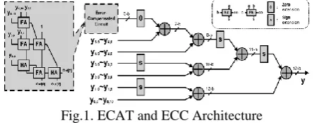
𝑦 𝑄−1 (𝑃−1) (25) The ECAT architecture propose in [15] is illustrated in Fig 1 below for (P,Q)=(12,6), where block FA indicates a full-adder cell with three inputs (a, b, and c) and two outputs, a sum (s) and a carry-out (co). Also, block HA indicates half-adder cell with two inputs (a and b) and two outputs, a sum (s) and a carry-out (co).
Fig.1. ECAT and ECC Architecture
IV.
I
MPLEMENTATION OFI
MAGEC
OMPRESSIONA
PPLICATIONU
SINGECAT
The 2-D transform can be carried out with two passes of 1-D transforms. The separability property of 2-D DCT/IDCT allows the transform to be applied on one dimension (row) then on the other (column). This technique requires 2N instances of N-point 1-D DCT to
implement an N x N 2-D DCT. The 2-D DCT of a data matrix is defined as equation (26)
𝑍 = 𝐶. 𝑋. 𝐶𝑇 (26)
Where X is the data matrix, C is the matrix of DCT Coefficients, and CT is th transpose of C.
An expanded form of above equation is shown in equation (27).
𝑍 =
𝐶00 𝐶01 … 𝐶07 𝐶10 𝐶11 … 𝐶17 ⋮ ⋮ ⋮ ⋮ 𝐶70 𝐶71 … 𝐶77
𝑋00 𝑋01 … 𝑋07 𝑋10 𝑋11 … 𝑋17 ⋮ ⋮ ⋮ ⋮ 𝑋70 𝑋71 … 𝑋77
𝐶00 𝐶10 … 𝐶70 𝐶01 𝐶11 … 𝐶71 ⋮ ⋮ ⋮ ⋮ 𝐶07 𝐶17 … 𝐶77
(27)
Where, for an N x N data matrix, the co-efficient values in the above matrix can be represented as shown in equation (28).
𝑐
𝑘,𝑙=
2 𝑁
𝑐𝑜𝑠
2𝑘−1 𝑙−1 𝜋
2𝑁
(28)
The 2-D DCT (8 x 8 DCT) is implemented by the row-column decomposition technique. We first compute the 1-D 1-DCT (8 x 1 1-DCT) of each column of the input data matrix X to yield XTC after appropriate rounding or truncation, the transpose of the resulting matrix, CTX, is stored in an transpose buffer. We then compute another 1-D 1-DCT (8 x 1 1-DCT) of each row of CTX to yield the desired 2-D DCT as defined in equation above. A block diagram of the design is shown in Fig 2 below.
Fig. 2. 2D DCT using Row-Column Decomposition
The test image is converted to grayscale using MATLAB utility function rgb2gray() and read as multiple 8x8 blocks from the implemented ModelSim testbench code. The 8x8 block is simulated using the proposed system. As illustrated in Fig. 2, 2D DCT is performed in two steps by using the same 1D DCT core proposed. In first step, 1D DCT is performed on each of the rows of 8x8 block and output is written to intermediate buffer. In second step, 1D DCT is performed again on all the columns of 8x8 blocks from the intermediate buffer and output captured from this step is the 2D DCT output of the test image.
The eight separated ECATs work simultaneously as shown in Fig. 4, enabling high-speed applications to be achieved. After the data output from the DA-Matrix is completed, the transform output will be completed during one clock cycle by the proposed ECATs. In contrast, the traditional shift-and-add architecture requires Q clock cycles to complete the transform output Z, if the DA-precision is Q bits.
Copyright © 2013 IJECCE, All right reserved 2-D DCT core has a latency of 10 clock cycles and is
operated at 100 MHz. As a result of the 8 parallel outputs, the proposed 2-D DCT core can achieve a throughput rate of 800 Mpixels per second, meeting the 1080 p high definition television (HDTV) specifications for 200 MHz based on low power operations.
Fig.3. 2D DCT FLOW
Fig.4. ECAT DA-DCT Flow
V.
R
ESULTS ANDD
ISCUSSIONThe 2-D DCT architecture and the implementation were discussed in the previous chapters. Now this chapter deals with the simulation and synthesis results of the implemented 1-D 8-point DCT. Here ModelSim tool is used in order to simulate the design and checks the functionality of the design. Once the functional verification is done, the design will be taken to the Xilinx tool for Synthesis process and the net-list generation.
The test image “Mushroom” shown in Fig. 5 is used to check the system accuracy is comprised of 32 x 32 pixels with each pixel being represented by 8-bit 256 gray level data.
Fig.5. Original Image 32x32
Copyright © 2013 IJECCE, All right reserved Fig.6. DCT Image 32x32
The transformed mage is fed into MATLAB to compute the inverse DCT using 64-bit double-precision operations. The reconstructed image using MATLAB IDCT function is shown in Fig. 7 below.
Fig.7. Reconstructed image 32x32
PSNR calculation is performed on the reconstructed image to check if desired accuracy is achieved with the proposed architecture. PSNR is used for measuring the quality of compressed image. Higher PSNR values represent good quality in compression. PSNR for test image was calculated approximately 45dB was achieved with this implementation
Proposed implementation is synthesized using Xilinx ISE 10.1. The synthesis report is shown in Fig. 8 below.
Fig.8. Xilinx synthesis report
The proposed 2-D DCT core synthesized by using Xilinx ISE 10.1 and the Xilinx XC3S500 FPGA can achieve around 500 megapixels per second (M-pels/sec) throughput rate. Table I compares the proposed 2-D DCT core with previous FPGA implementations. The throughput rate is comparable to other results for given P,Q values of 12,9 along with high PSNR value.
Table I : Comparison of 2-D DCT Architectures in FPGA
FPGA-Chip XC2VP30 XC3S200 XC3S500
Architecture [15] [11] [15] Proposed
Number of 4
input LUTs 2990 2271 2847 931
Number of
Slices 1872 1221 1585 503
Number of Slice Flip Flops
1837 616 1817 971
Throughput
(M-pels/s) 792 400 488 500
Clock Frequecy (MHz)
99 50 61 99
VI.
C
ONCLUSION AND FUTURE SCOPEThe Distributed Arithmetic Discrete Cosine Transform (DA DCT) was designed successfully and the coding was done in Verilog HDL. The RTL simulations were performed using ModelSim III XE 6.4b from Mentor Graphics. The synthesis was done using Xilinx ISE 10.1. DA DCT Design is verified for all test cases. The DA DCT works properly for all the test values and achieved high PSNR values by maintaining the high throughput values.
Future scope of the Work
1) This work can be improved by implementing JPEG 2000 Image compression standard in which ordinary DCT transformation part can be replaced by our Distributed Arithmetic Discrete Cosine Transform (DA DCT) Design.
2) The 8-Point Distributed Arithmetic Discrete Cosine Transform (DA DCT) Design can be made to 16, 32-point Distributed Arithmetic Discrete Cosine Transform (DA DCT) by making minor modifications to the code.
3) This work can be extended in order to increase the accuracy by increasing the level of transformations. 4) This can be used as a part of the block in the full
Copyright © 2013 IJECCE, All right reserved
R
EFERENCES[1] Y.Wang, J. Ostermann, and Y. Zhang, Video Processing and Communications, 1st ed. Englewood Cliffs, NJ: Prentice-Hall, 2002.
[2] Y. Chang and C.Wang, “New systolic array implementation of the 2-D discrete cosine transform and its inverse,” IEEE Trans. Circuits Syst. Video Technol., vol. 5, no. 2, pp. 150–157, Apr. 1995.
[3] C. T. Lin, Y. C. Yu, and L. D. Van, “Cost-effective triple-mode reconfigurable pipeline FFT/IFFT/2-D DCT processor,” IEEE Trans. Very Large Scale Integr. Syst., vol. 16, no. 8, pp. 1058– 1071, Aug. 2008.
[4] S. Uramoto, Y. Inoue, A. Takabatake, J. Takeda, Y. Yamashita, H. Yerane, and M. Yoshimoto, “A 100-MHz 2-D discrete cosine transform core processor,” IEEE J. Solid-State Circuits, vol. 27, no. 4, pp. 492–499, Apr. 1992.
[5] S. Yu and E. E. S. , Jr., “DCT implementation with distributed arithmetic,” IEEE Trans. Comput., vol. 50, no. 9, pp. 985–991, Sep. 2001.
[6] P. K. Meher, “Unified systolic-like architecture for DCT and DST usi distributed arithmetic,” IEEE Trans. Circuits Syst. I, Reg. Papers, vol.53, no. 12, pp. 2656–2663, Dec. 2006. [7] A. M. Shams, A. Chidanandan, W. Pan, and M. A. Bayoumi,
“NEDA: A low-power high-performance DCT architecture,” IEEE Trans. Signal Process., vol. 54, no. 3, pp. 955–964, Mar. 2006.
[8] M. R. M. Rizk and M. Ammar, “Low power small area high performance 2D-DCT architecture,” in Proc. Int. Design Test Workshop, 2007, pp. 120–125.
[9] Y. Chen, X. Cao, Q. Xie, and C. Peng, “An area efficient high performance DCT distributed architecture for video compression,” in Proc. Int. Conf. Adv. Comm. Technol., 2007, pp. 238–241.
[10] C. Peng, X. Cao, D. Yu, and X. Zhang, “A 250 MHz optimized distributed architecture of 2D 8�8 DCT,” in Proc. Int. Conf. ASIC, 2007, pp. 189–192.
[11] [C. Y. Huang, L. F. Chen, and Y. K. Lai, “A high-speed 2-D transform architecture with unique kernel for multi-standard video applications,” in Proc. IEEE Int. Symp. Circuits Syst., 2008, pp. 21–24.
[12] S. S. Kidambi, F. E. Guibaly, and A. Antonious, “Area-efficient multipliers for digital signal processing applications,” IEEE Trans. Circuits Syst. II, Exp. Briefs, vol. 43, no. 2, pp. 90–95, Feb. 1996.
[13] K. J. Cho, K. C. Lee, J. G. Chung, and K. K. Parhi, “Design of low-error fixed-width modified booth multiplier,” IEEE Trans. Very Large Scale Integration. (VLSI) Syst., vol. 12, no. 5, pp. 522–531, May 2004.
[14] L. D. Van and C. C. Yang, “Generalized low-error area-efficient fixedwidth multipliers,” IEEE Trans. Circuits Syst. I, Reg. Papers, vol. 52, no. 8, pp. 1608–1619, Aug. 2005.
[15] High Throughput DA-Based DCT With High Accuracy Error-Compensated Adder Tree. Yuan-Ho Chen, Tsin-Yuan Chang, and Chung-Yi Li. IEEE Vol. 19, No. 4, April 2011
A
UTHOR’
SP
ROFILEK. V. S. P. Pravallika
was born in kothagudem on July 4th 1988. She is pursuing her M.Tech. in Advanced VLSI System Design from CVSR College of Engineering, Hyderabad, A.P. She pursued her BTech in Electronics and Communication Engineering from Sai Spurthi Institute of Technology, Sathupally, A.P. in 2009.