* Corresponding author. Fax: +98-21-66405846. E-mail address: [email protected] (E. Keshavarz Alamdari).
Journal Homepage: ijmge.ut.ac.ir
The effect of chemical composition and burning temperature on pellet
quality
Aref Sardari
a, Eskandar Keshavarz Alamdari
b, *, Mohammad Noaparast
c, Sied Ziaedin Shafaei
Tonekaboni
caDepartment of Mining Engineering, Tehran Science and Research branch, Islamic Azad University, Tehran, Iran
bDepartment of Mining and Metallurgical Engineering, Amirkabir University of Technology, Tehran, Iran
cSchool of Mining Engineering, University of Tehran, Tehran, Iran
A
B
S
T
R
A
C
T
The effect of pellet chemical composition and burning temperature on pellets’ properties of the Gol-e-Gohar hematite recovery plant was investigated in this study. Green pellets of different sodium hydroxide ratio and hydrated lime were prepared as well. Then the pellets were burnt in a muffle kiln under different temperature conditions. The Design Expert software was employed to explore the optimized conditions and to model the effective parameters in the pelletizing process. The wet compressive strength of green pellets was determined to be 1.4-1.5 kilograms per pellet. The porosity of burnt pellets at different temperatures was determined between 16% to 38%. The firing process of green pellets provided discrimination between the outer layer and the central part of individual pellets. The model developed by the experiment design software showed that the temperature was the most effective parameter on increasing the compressive strength. While the burn temperature increased the cold compressive strength, it reduced the porosity of pellets. The cold compressive strength of burnt pellets was improved through increasing the temperature. However, a further increase in temperature led to a decrease in the cold compressive strength, because of hematite decomposition into secondary magnetite.
Keywords : Experiment design, Burn Temperature, Compressive Strength, Pellet, SEM
1.
Introduction
Iron ore pelletizing typically involves balling of fine iron powders on a rotating disk to produce wet pellets and their induration in a furnace to produce burnt pellets [1]. The parameters of pelletizing are specific to a given ore or concentrate. Oxide pellets with advantages of uniform size, high strength, good permeability, improved reducibility, swelling and softening melting characteristics are used in the reduction step. Green pellets should be in desirable diameter size and have sufficient mechanical strength to enable their safe transportation from pelletizing facilities to the induration machine [2].
Many researchers have investigated pelletizing from various viewpoints; Yang [1] showed that blending raw materials would affect the quality of pellets; Forsmo [2] revealed that the fine particles could increase the compressive strength of green pellets and Umadevi [3] showed the importance of the burning step on hematite pelletization. Forsmo [4] investigated the Influence of green pellet properties on pelletizing magnetite iron ores and revealed that excessive grinding of pelletization raw materials, both magnetite concentrate and additives, could cause severe problems and step-wise changes in the oxidation and sintering procedure without resulting in any additional gain in the mechanical strength of green pellets. Excessive grinding would increase the surface of green pellets and would cover the surface with oxides, decreasing the oxidation rate.
Optimizing the pelletization process is highly beneficial and it has been reported that it would decrease bentonite consumption from 0.66%
to 0.33% [5]. Although bentonite could be activated by using a slight amount of sodium carbonate, Mohamed [6] showed the pellets produced by conventional bentonite to have higher strength than those of activated bentonite. According to Forsmo, the hematite to magnetite conversion happens at 1200°C and the oxidized layer starts to swell as a result of this conversion [9].
Umadevi [10] optimized the burn temperature for hematite pellets and showed that the burn temperature of the induration machine would strongly influence the physical and metallurgical properties of the pellet. The optimum physical and metallurgical properties of the hematite pellet reported by Umadevi increased from 0.7 to 1.30%, by adding carbon to the system. Generally, the energy needed for hematite pellet production is greater than that of consumed for magnetite pellets [8]. Majumder [7] simulated the induration process of pelletizing to find a proper process time extent. Martinez investigated the induration of pellets prepared from mixed magnetite–hematite concentrates [8]; however, all of the effective parameters have not been investigated yet. Tang investigated the oxidation of magnetite pellet and proved that during the process of magnetite pellet heating, oxidization would occur in the pellet volume but an unoxidized core would be remained [9].
Feng [10] investigated the drying and preheating of pellets and presented a mathematical model. Another thermo-kinetic model was proposed by Cross [11] for the whole induration process with a general focus on drying, preheating, burning, after-burning, and cooling. Since pelletization is conducted in large scales and it is affected by many parameters, developing optimized models and conducting pre-production calculations are beneficial to the final results.
Article History:
Although several studies have been carried out on thermal conditions of magnetite pellets [12, 13], and the optimum parameters have been investigated in the literature, a more precise investigation on the effect of temperature and other process conditions seems necessary.
This work aims to explore the effect of various parameters on pellet quality in the burn step using supportive tools such as experiment design software and SEM.
2.
Materials and methods
2.1. Materials
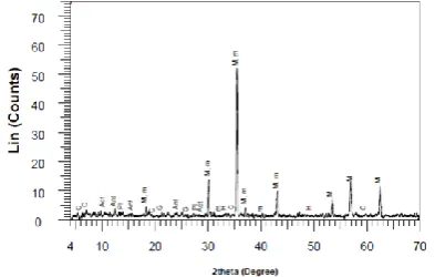
The representative sample for producing the pellets was obtained from the outlet of the magnetite conveyer (flotation product) in the Gol-e-Gohar hematite recovery plant. X-ray diffraction patterns showed that magnetite was the dominant phase in this sample. Some traces of hematite and actinolite, calcite, anorthite and geolite were also identified (Fig. 1). According to sieve analysis, the d80 index of the sample was 38μ.
Fig. 1. X-ray diffraction pattern of magnetite concentrate (M: magnetite, H: hematite, Act: actinolite, C: Calcite, Ant: anorthite, G: geolite). The chemical composition of the magnetite concentrate and bentonite measured using XRD is presented in Table 1. Also, sodium hydroxide, as bentonite activator, and lime, were used to produce green pellets.
Table 1. Chemical composition of magnetite concentrate and bentonite. L.O.I
(%) MgO
(%) CaO
(%) Al2O3
(%) SiO2 (%)
P (%) S (%) FeO (%) Fe (%)
0.64 1.01 0.05 0.01 0.17 0.001 0.112 28.39 70.05 Magnetite Concentrate
0.75 2.35 2.69 12.42 66.65 0.014 0.058 -2.03 Bentonite
2.2. Methods
Due to a low specific surface area (1300cm2/g) and in order to achieve more uniform distribution in particle size, the dried sample was subjected to further grinding. A 1-ton semi-industrial ball mill with a rotation rate of 70rpm was employed at the Gol-e-Gohar Pelletizing Laboratory. The specific surface area of the magnetite concentrate and bentonite used in experiments were 2050 cm2/g and 3042 cm2/g, respectively
.
Blaine air-permeability apparatus is a permeable pressure-variable testing device. The value of the specific surface area was measured based on the required time for a given volume of air to pass through the sample bed and barometer pressure drop at two specific points: Hinitial and Hfinal [14]. Blaine air-permeability apparatus was used to determine the specific surface area of bentonite and magnetite concentrate.
According to the literature, the ingredients used to produce green pellets are magnetite concentrate, bentonite, water, sodium hydroxide (bentonite activator) and lime which are used in various proportions. The portions of sodium hydroxide and lime for each pellet are given in Table 2. The amount of water and bentonite in all tests was adjusted 8wt% and 0.7wt%, respectively. In order to prepare green pellets, the raw materials were mixed by Erich’s mixing device and then, the prepared
paste was fed to a pelletizing disk (90cm in diameter, 45° angle and rotation rate of 20rpm).
Table 2. Portions of sodium hydroxide and lime added to green pellets. Pellet 1 Pellet 2 Pellet 3 Pellet 4 Pellet 5 Pellet 6 Pellet 7 Industrial lime
(wt %) 1.5 1 0.5 - - - -
NaOH (wt %) - - - 0.045 0.03 0.015
-The moisture of samples paste was calculated by measuring the weight loss caused by moisture removal after 15 minutes of heating the samples in a hygroscope at 130°C. This scientific standard method is employed elsewhere [15].
The properties of green pellets, such as the drop number and wet compressive strength, were also measured. The drop number of a pellet is the number of falls before the pellet is crushed [16]. The drop number was determined by repeatedly dropping green pellets from a height of 46cm over a steel sheet. The green pellets were dried at 110°C for 24 minutes and then subjected to induration in an Exciton Ex-1500 muffle furnace with dimensions 16×15.5×22 cm3 at different temperatures and under air atmosphere. After the pellets were slowly cooled in the furnace (300°C), they were removed from the furnace to reach the room temperature. The cooling rate depends on the heating duration and the furnace final temperature varying from 70 to 150 minutes.
The cold compressive strength of indurated pellets was determined by crushing 30 pellets, according to the scientific standard, by means of Kogel FPG 7/20-5-010s apparatus and the average CCS value was measured.
In order to measure the porosity of burnt pellets, they were placed in boiling water at 300°C for 30 minutes.
Table 3 represents the temperature and time conditions in the pellet burning process and Table 4 shows the specifications of resulted burnt pellets. The retention time at the final temperatures was set 10 minutes for all tests. The heating rate varied throughout the process. However, the average heating rate was 15.84 °C/min. Moreover, the temperature was monitored using the screen on the burning kiln.
Table 3. The temperature and time conditions in the pellet burning process.
Test No. Time to reach final temperature (min) Final temperature (°C) Cooling time (min)
1 20 650 70
2 25 850 80
3 30 1050 90
4 35 1230 100
5 40 1250 110
6 45 1280 120
7 50 1300 130
8 55 1320 140
9 60 1350 150
Smooth cross-sections of burnt pellets were provided to conduct microscopic analyses [17]. Optical and SEM micrographs were taken to study the obtained results. Pellet No. 5 (Table 4) represents the current conditions in the Gol-e-Gohar pelletizing plant. Based on the results obtained from chemical composition analyses of burnt pellets and oxidation starting time, five pellets with the same chemical composition as pellet No. 5 were burnt at final temperatures for SEM analysis.
2.3. Designing the experiments
A series of experiments were designed using Design Expert 7 Trial (State Ease, Inc., Minneapolis, MN, USA) to explore the relationship between the responses (FeO%, S%, porosity e%, CCS) and the process parameters (NaOH, Lime, Temperature). The dataset was value surveyed by ANOVA and a suitable model was conducted according to the experimental data. The Response Surface Method (RSM) and Historical Data were used as well.
3.
Results and Discussion
necessary to maintain a reasonable pellet diameter so that burning occurs uniformly throughout the pellets.
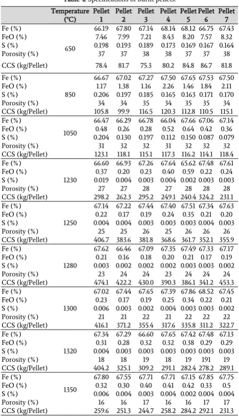
Table 4. Specifications of burnt pellets.
Pellet 7 Pellet 6 Pellet 5 Pellet 4 Pellet 3 Pellet 2 Pellet 1 Temperature (°C) 67.43 66.75 68.12 68.14 67.14 67.80 66.19 650 Fe (%) 8.32 7.57 8.20 8.43 7.21 7.99 7.46 FeO (%) 0.164 0.167 0.169 0.173 0.189 0.193 0.198 S (%) 38 37 37 38 38 37 37 Porosity (%) 81.8 86.7 84.8 80.2 75.3 81.7 78.4 CCS (kg/Pellet) 67.50 67.53 67.65 67.50 67.27 67.02 66.67 850 Fe (%) 2.11 1.84 1.46 2.26 1.16 1.38 1.17 FeO (%) 0.170 0.171 0.163 0.165 0.185 0.197 0.206 S (%) 34 35 35 34 35 34 34 Porosity (%) 115.1 110.5 112.8 120.3 116.5 99.9 105.8 CCS (kg/Pellet) 67.14 67.06 67.66 66.04 66.78 66.29 66.47 1050 Fe (%) 0.36 0.42 0.64 0.52 0.28 0.26 0.48 FeO (%) 0.079 0.087 0.150 0.112 0.197 0.130 0.204 S (%) 32 32 32 31 32 32 31 Porosity (%) 118.4 114.1 116.2 117.3 115.1 118.1 123.1 CCS (kg/Pellet) 67.61 67.48 65.62 67.64 67.26 66.93 66.60 1230 Fe (%) 0.24 0.22 0.59 0.40 0.23 0.20 0.37 FeO (%) 0.003 0.003 0.002 0.004 0.003 0.004 0.019 S (%) 28 28 28 27 28 27 27 Porosity (%) 231.1 324.2 240.4 249.1 295.2 262.3 298.2 CCS (kg/Pellet) 67.63 67.34 67.51 67.40 67.44 67.22 67.14 1250 Fe (%) 0.20 0.21 0.35 0.24 0.19 0.17 0.22 FeO (%) 0.003 0.004 0.003 0.003 0.003 0.004 0.004 S (%) 26 26 26 25 26 25 25 Porosity (%) 355.9 352.1 361.7 368.6 381.8 383.6 406.7 CCS (kg/Pellet) 67.17 67.33 67.49 67.35 67.09 66.46 67.62 1280 Fe (%) 0.19 0.17 0.21 0.20 0.18 0.16 0.21 FeO (%) 0.002 0.003 0.003 0.002 0.002 0.002 0.003 S (%) 24 24 24 23 24 24 23 Porosity (%) 453.3 341.2 386.1 390.3 430.0 422.2 474.1 CCS (kg/Pellet) 67.45 68.52 67.86 67.39 67.65 67.44 67.02 1300 Fe (%) 0.21 0.22 0.34 0.25 0.19 0.17 0.23 FeO (%) 0.002 0.003 0.003 0.004 0.002 0.003 0.006 S (%) 22 22 22 21 22 21 21 Porosity (%) 322.7 311.2 335.8 317.6 355.4 371.2 416.1 CCS (kg/Pellet) 67.13 67.48 67.42 67.65 66.60 67.29 67.34 1320 Fe (%) 0.29 0.29 0.38 0.32 0.32 0.28 0.31 FeO (%) 0.003 0.003 0.003 0.003 0.003 0.003 0.004 S (%) 19 191 19 18 19 18 18 Porosity (%) 289.1 278.2 282.4 291.1 309.2 325.1 404.2 CCS (kg/Pellet) 67.75 67.85 67.15 67.71 67.71 67.55 67.80 1350 Fe (%) 0.5 0.33 0.42 0.41 0.40 0.30 0.32 FeO (%) 0.004 0.004 0.002 0.004 0.003 0.004 0.006 S (%) 17 17 16 16 17 16 16 Porosity (%) 231.3 292.1 284.2 258.2 244.7 251.3 259.6 CCS (kg/Pellet)
The drop number was observed to be almost constant (3.8-4.4) in all experiments, due to the same moisture and bentonite contents (8% and
0.7%, respectively) and also the same specific surface area (2050cm2/g) applied in all experiments. The partial increase in the drop number, however, might be attributed to the growth in mechanical and chemical interactions between the particles. As the surface area increased, the distance between the particles reduced and resulted in more interlocked particles.
Pellet strength in the green form is due to the hydraulic bonds between the particles and bentonite; in fact, a bentonite gel is formed by absorbing water. The volume of bentonite gel increases as the absorption capacity of water increases. The gel covers iron ore concentrate particles and increases their adhesive bonds [21]
.
Additionally, the inflation caused by water absorption in bentonite increases the strength of the pellet. The compressive strength of green pellets was determined by pressing 10 pellets on a digital balance and recording the displayed weight when the pellets crushed. The average number was reported as the wet compressive strength which was in the range of 1.4-1.5 kilograms per pellet. The results of chemical composition analysis, porosity and cold compressive strength (CCS) measured at different temperatures (final temperatures) are given in Table 4. As shown in the Table, while the burn temperature increased the cold compressive strength, it reduced the porosity of the final product on the other hand.3.1. Microscopic analysis
In order to perform accurate studies on crack initiation in the pellets, microstructural studies were carried out on seven types of produced green pellets. All experiments were repeated twice to assure the accuracy of the obtained results. As previously mentioned, pellet No. 5 had the same chemical composition as the processing line in the Gol-e-Gohar pelletizing plant; therefore, this pellet was chosen as the representative sample for the pelletization plant.
The burnt pellets were cut from the center and then, the cross-sections were polished with sandpapers of different numbers. The smoothness of resulted surfaces for the final samples was high (up to 1μ). Polarized microscopy was carried out with magnification orders of ×160 and ×500 at the Geological Survey of Iran.
Fig. 2 shows the surface and microscopic image of pellet No. 5. Grooves can be seen on the surface revealing the lower layer of the pellet which is seen in a different color. Some cracks were initiated at the end of segregations and have propagated over the pellet due to the relatively distributed large voids. Segregations formed as a result of structural stresses between hematite (oxidized magnetite) and magnetite; in fact, these two phases have different crystalline lattices and sintering behaviors which would lead to structural stresses [22]. The main reason for existing two phases and, consequently, different behaviors originated from the oxidation lag between the central area and the outer layer of magnetite.
Fig. 2. Segregations near pellet surface areas in Pellet No. 5 at magnification order of ×160 at 650°C. Color differences show segregation. In order to explore this issue, the pellets were cut from two sections,
one near the surface and the other from the central area. Optical and SEM micrographs regarding these areas were taken at the magnification order of ×500 (Figs 3, 4 and 5). The dark areas indicate the existing voids and pores over the pellet’s cross-section, while light and grey areas
represent iron oxide phases coalesced each other via narrow glassy bands.
these phases, it is evident that un-oxidized magnetite is the dominant phase in the central area of the pellet. On the other hand, hematite dominates in marginal zones. Therefore, the formation of these two phases with different metallurgical behaviors, in terms of the crystalline lattice, air bubbles and recrystallization temperature of particles, led to the creation of structural stresses and, consequently, the separation of the outer layer from the central part [22].
Fig. 3. Polarized micrographs of central areas in Pellet No. 5 at a magnification order of ×500: a: 1350 °C and b: 1320 °C.
Fig. 4. Polarized micrographs of marginal areas in Pellet No. 5 at a magnification order of ×500: a: is marked, 1300 °C, and b: 1250 °C. Hematite and Magnetite are
marked.
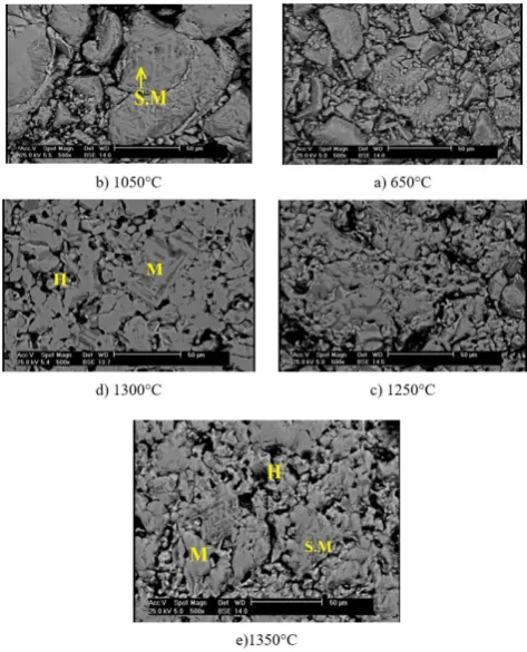
The SEM micrographs of the pellets burnt at different temperatures are shown in Fig. 5. The brighter areas represent hematite, the darker areas are magnetite, and the deep black spots are pyrite [23]. As seen, temperature increase from 650 °C to 1300 °C decreased the surface heterogeneity and improved the continuity as a result of grain refinement due to recrystallization. Indeed, more possible sites would be available to bridge with oxygen by increasing the temperature. The pellets contain pores left from the evaporated interlocked water. Oxygen molecules reach the core via pores, easing the nucleation process [2].
These sites provide the required space for hematite formation through the oxidation reaction. They also play an important role in the recrystallization process and microstructures homogeneity. Microstructures homogeneity increases the cold compressive strength of indurated pellets. The glassy phase formed among the particles is obtained through reactions between impurities such as Al2O3 and SiO2 with iron oxides and improves the cold compressive strength. In fact, the flow-ability of the glassy phase increases at high temperatures [24]. Consequently, the glassy phase distributes better amongst the particles and increases the adhesion between hematite particles and improves the strength. However, as Fig. 5 shows, an additional increase in temperature to 1350°C did not show a specific improvement in surface heterogeneity and continuity since the microstructure did not seem to become smoother as the temperature increased to 1350°C.
Cold compressive strength, FeO content, sulfur content and hematite to magnetite ratio of Pellet No. 5 burnt at different temperatures are given in Table 5.
According to Table 5, the cold compressive strength of burnt pellets was improved by rising the burn temperature from 650°C to 1280°C. Moreover, it is evident from the microscopic pictures that the Hematite/Magnetite content was constant during the last three stages. This might result from the alteration of hematite to magnetite which causes the halt and reversion of hematite magnetite alteration.
Fig. 5. SEM micrographs of Pellet No. 5 at final temperatures (magnification order: ×500).
Table 5. Cold compressive strength, FeO and sulfur contents and hematite to magnetite ratio of Pellet No.5 samples burnt at different temperatures.
Hematite/Magnetite (%) CCS
(kg/Pellet) S (%)
FeO (%) Temperature
(°C)
60/40 84.8
0.169 8.2
650
50/50 112.8
0.163 1.46 850
30/70 116.2
0.150 0.64 1050
20/80 240.4
0.002 0.59 1230
15/85 361.7
0.003 0.36 1250
10/90 386.1
0.003 0.21 1280
15/85 335.8
0.003 0.33 1300
15/85 282.4
0.003 0.38 1320
15/85 284.2
0.002 0.42 1350
Several reactions occur during the pellet induration process, including the formation of solid phases between impurities and iron oxides, slag formation, and magnetite oxidation to hematite and decomposition of hematite to magnetite [2]
.
Each of these reactions affects the induration process and the properties of the final product. Slag bands caused by impurities reactions may create bonds between iron concentrate particles and improve the cold compressive strength of indurated pellets. As the temperature increased, sintering took place and magnetite converted into hematite, causing the coalescence of microcracks and micropores. Therefore, it resulted in the filling of pores by impurities and slag bands.Also, most of the solid sulfur converted into gaseous sulfur as the temperature increased; therefore, the sulfur content decreased in the burnt pellets.
strength. A further increase in burn temperature from 1280°C to 1350°C reduced the compressive strength of burnt pellets. This could be the result of hematite decomposition in this temperature and the formation of secondary magnetite. Secondary magnetite divides the microstructure into two phases and decreases the compressive strength.
The fraction of Hematite/ Magnetite remained constant as seen in Table 5. The particular reason for this phenomenon might be that a thick layer of oxide covered the pellet and prevented the core from receiving enough oxygen.
4.
Conclusions
The obtained results in the present work can be summarized as follows:
- The wet compressive strength of green pellets was determined to be 1.4-1.5 kilograms per pellet.
- While the burn temperature increased the cold compressive strength, it reduced the porosity of burnt pellets.
- The porosity of burnt pellets at different temperatures was determined to range between 16% and 38%.
- The modeling by Design Expert showed that among the studied parameters (temperature, lime and sodium hydroxide), the temperature was the most effective parameter on all responses (FeO%, S%, porosity, CCS).
- The burn process of green pellets discriminated against the outer layer and the central part of individual pellets.
- The temperature rise to about 1300°C decreased surface heterogeneity and improved continuity. However, an additional increase in temperature to 1350°C did not improve surface heterogeneity and continuity.
- Cold compressive strength of burnt pellets was improved by increasing the temperature from 650 °C to 1280 °C.
- High burn temperatures lead to higher hematite yield. This further oxidation increased bonding among iron ore particles and, consequently, improved the cold compressive strength of burnt pellets.
An additional increase in temperature from 1280°C to 1350°C decreased the cold compressive strength of burnt pellets; as a result of the decomposition of hematite to secondary magnetite in this condition. This created a two
-
phase microstructure and decreased the cold compressive strength.REFERENCES
[1] Majumder, S., Natekar, P.V., & Runkana, V. (2009). Virtual indurator: A tool for simulation of induration of wet iron ore pellets on a moving grate. Computers & Chemical Engineering, 33(11), 41-52.
[2] Von Bogdandy, L., & Engell, H.J. (1971). The Reduction of Iron Ores Book. Springer, 1-575.
[3] Yang, L. (2005). Sintering fundamentals of magnetite alone and blended with hematite and hematite/goethite ores. ISIJ international. 45, 469-76.
[4] Forsmo, S., Samskog, P.O., Björkman B. A. (2008). study on plasticity and compression strength in wet iron ore green pellets related to real process variations in raw material fineness. Powder technology, 181, 321-330.
[5] Umadevi, T., Kumar, P.P, Kumar, P., Lobo, N.F., & Ranjan, M. (2008). Investigation of factors affecting pellet strength in straight grate induration machine. Ironmaking & steelmaking. 35(5), 321-326.
[6] Forsmo, S. (2007). Influence of green pellet properties on pelletizing of magnetite iron ore. Doctoral thesis, Luleå: Luleå
tekniska universitet, 1-106.
[7] Kawatra, S.K, & Ripke, S.J. (2002). Effects of bentonite fiber formation in iron ore pelletization. International journal of mineral processing. 65, 141-149.
[8] Mohamed, O., Shalabi, M., El-Hussiny, N., Khedr, M., & Mostafa, F. (2003). The role of normal and activated bentonite on the pelletization of barite iron ore concentrate and the quality of pellets. Powder Technology. 130, 277-282.
[9] Forsmo, S.P.E., Forsmo, S.E., Samskog, P.O., & Bjrkman B.M.T., (2008). Mechanisms in Oxidation and Sintering of Magnetite Iron Ore Green Pellets. Powder Technology. 183(2), 247–259. doi:10.1016/j.powtec.2007.07.032.
[10] Umadevi, T., Lobo, N.F., Desai, S., Mahapatra, P.C., Sah, R., & Prabhu, M. (2013). Optimization of firing temperature for hematite pellets. ISIJ international. 53, 1673-1682.
[11] Martinez, N.P., Trejo, M.H., Estrella, R.M., Román, M.J.C., Esparza, R.M., & Villareal, M.C. (2014). Induration Process of Pellets Prepared from Mixed Magnetite–35% Hematite Concentrates. ISIJ international. 54, 605-612.
[12] Tang, M., Cho, H.J., & Pistorius, P.C. (2014). Early gaseous oxygen enrichment to enhance magnetite pellet oxidation. Metallurgical and Materials Transactions B. 45, 1304-1314.
[13] Feng, J-x., Zhang, Y., Zheng, H-w., Xie, X-y., & Zhang, C. (2010). Drying and preheating processes of iron ore pellets in a traveling grate. International Journal of Minerals, Metallurgy, and Materials. 17, 535-540.
[14] Cross, M., & Blot, P. (1999). Optimizing the operation of straight-grate iron-ore pellet induration systems using process models. Metallurgical and Materials Transactions B. 30, 803-813.
[15] Ferreira, S., Siguin, D., & Garcia, F., (1994). Thermal analysis of sintering of magnetite pellets. Ironmaking & steelmaking. 21, 119-123.
[16] Ruiz Sierra, J., Badie, J., Chejne Janna, F. (1994). Non-isothermal conditions inside magnetite pellet due to its oxidation by air. Ironmaking & steelmaking. 21, 114-117.
[17] ASTM C. 204. (1998). Standard Test Method for Fineness of Hydraulic Cement by Air Permeability Apparatus. Annual Book of ASTM Standards.
[18] Standard M.J. (2011). Iron Ores: Determination of Hygroscopic Moisture in Analytical Samples - Gravimetric, Karl Fisher and Mass-loss Methods (first Revision) (ISO 2596:2006, IDT): Department of Standards Malaysia.
[19] Publication B.S. ISO 4700: (2015). Iron ore pellets for blast furnace and direct reduction feedstocks, Determination of the crushing strength.
[20] Ramdohr P. (2013). The ore minerals and their intergrowths: Elsevier.
[21] Forsmo, S.P.E., A.J., Apelqvist, B.M.T., Björkman, & Samskog, P.O. (2006). Binding Mechanisms in Wet Iron Ore Green Pellets with a Bentonite Binder. Powder Technology. 169 (3): 147–158. doi:10.1016/j.powtec.2006.08.008.
[22] Barbosa, P.F. & Lagoeiro, L. (2010). Crystallographic texture of the magnetite-hematite transformation: Evidence for topotactic relationships in natural sample from Quadrilatero Ferriferi, Brazil, American Mineralogist, 95, 118-125.
Powder Technology, 284–291. doi:10.1016/j.powtec.2012.01.013.
[24] Clout, J.M.F., & Manuel, J.R. (2015). Mineralogical, Chemical,