R E S E A R C H
Open Access
Optimized intelligent control of a 2-degree of
freedom robot for rehabilitation of lower limbs
using neural network and genetic algorithm
Wahab Aminiazar
1*, Farid Najafi
2and Mohammad Ali Nekoui
3Abstract
Background:There is an increasing trend in using robots for medical purposes. One specific area is rehabilitation. Rehabilitation is one of the non-drug treatments in community health which means the restoration of the abilities to maximize independence. It is a prolonged work and costly labor. On the other hand, by using the flexible and efficient robots in rehabilitation area, this process will be more useful for handicapped patients.
Methods:In this study, a rule-based intelligent control methodology is proposed to mimic the behavior of a healthy limb in a satisfactory way by a 2-DOF planar robot. Inverse kinematic of the planar robot will be solved by neural networks and control parameters will be optimized by genetic algorithm, as rehabilitation progress. Results:The results of simulations are presented by defining a physiotherapy simple mode on desired trajectory. MATLAB/Simulink is used for simulations. The system is capable of learning the action of the physiotherapist for each patient and imitating this behaviour in the absence of a physiotherapist that can be called robotherapy. Conclusions:In this study, a therapeutic exercise planar 2-DOF robot is designed and controlled for lower-limb rehabilitation. The robot manipulator is controlled by combination of hybrid and adaptive controls. Some safety factors and stability constraints are defined and obtained. The robot is stopped when the safety factors are not satisfied. Kinematics of robot is estimated by an MLP neural network and proper control parameters are achieved using GA optimization.
Keywords:Rehabilitation, Robotic rehabilitation, Intelligent control, Impedance control, Adaptive control, Neural network, Genetic algorithm
Background
The process of strengthening muscles to their normal values is a costly labor which requires time and patience [1]. This process is named rehabilitation. An intelligent instrument that replaces the duty of the physiotherapist and can accomplish such routine physical movements without the guidance and assistance of a physiotherapist will simplify the process and lower the costs drastically [2]. There are many exercise machines for rehabilitation purposes like CPMs [2]. Nevertheless, these machines are used only for ankle function and because of their low degree of freedom, their poor dynamic efficiency
and prospect of high expense, they are used limitedly [3,4]. The most important machines used widely in many medical centers for therapy and rehabilitation pur-poses are LOKOMAT [5], ALEX [6] and LOPES [7]. These machines have high degree of freedom but their high cost causes them to be used limitedly. Moreover, their manipulation is hard and requires ingenuity. In addition, control system design is one of the major diffi-culties in construction of rehabilitation robots. Different approaches were developed to control movement of robot-aided therapy attached to human limbs [1,8-12]. It is observed that the devices developed for rehabilitation purpose usually employ two control methods including hybrid control (force and position control) and imped-ance control. Intelligent techniques, which are optimized based on therapy session, were used in few works [2,9]. * Correspondence:[email protected]
1
Department of Electrical Engineering, Science and Research branch, Islamic Azad University, Tehran, Iran
Full list of author information is available at the end of the article
The main purpose of the developed system in this study is to introduce a low-cost system to satisfy the patient safety by a flexible structure controlled by an intelligent control strategy. The control parameters will be changed based on the therapy of different stages and patient qualification, thus the hybrid and adaptive control are used for controlling the suggested system. Neural net-works are employed as the reference input of the pro-posed controller. Control parameters are optimized based on therapy sessions and safety factors and for this purpose a genetic evolutionary algorithm was applied. The suggested system can be used for rehabilitation of two limbs/joints (knee and hip).
Methods
Rehabilitation mode
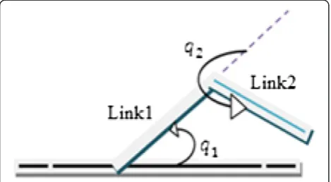
The proffered structure is based on the flexion and ex-tension movement for knee and hip [1]. For this purpose a 2-DOF planar robot is defined that can be attached to the trunk of lower limb (Figure 1).
In Figure 1, link 1 is aligned to the thigh and link 2 is aligned to the shank andq1٫q2are the angles of hip and knee, respectively and the limits of them are based on the flexion-extension of knee and hip process shown in Figure 1 and are written as:
0≤q1≤π
2 ð1Þ
7π
6 ≤q2≤2π ð2Þ
In robotic rehabilitation, the desired trajectory of ma-nipulator obtained from the physiotherapist and then the related variables of the robot such as angles and vel-ocity of them are computed based on inverse kinematic problem. Thereafter these parameters are used for con-trol of robot to track the desired trajectory. These issues will be described in the next stages.
Control strategy used in proposed algorithm
As mentioned earlier, neural networks are employed as the reference input of proposed control algorithm. Thus, the neural network and its usages in proposed strategies are explained first and then the proffered control strat-egy will be described.
Neural network
An important area of neural networks application is in the field of robotics. Usually, these networks are designed for learning and reconstructing complex non-linear mapping and have been widely used in the identi-fication and control of a manipulator, which is the most important form of an assistant robot, and in tracking a trajectory based on sensory information. Generally, kinematics of parallel robot are non-linear problems and difficult to solve, thus an MLP neural network is used to estimate the joint variables. The second idea in using neural networks is originated from the results of experi-ments showing that there are training vulnerability centers in the adult mammalian spinal cord which acti-vate and control motor neurons that are responsible for walking patterns [13-15]. These walking patterns that have been previously been reserved in can be replaced by other neurons. It means each neuron can be consid-ered as a walking pattern.
The MLP neural network used in suggested method has two layers tansig activation function in layer (1) and activation purelin function in layer (2). The best number of neurons in layer (1) is obtained from an it-eration algorithm. The Levenberg-Marquardt back propagation or trainlm algorithm is used for network training.
Control strategy
Control strategies of rehabilitation systems can be classi-fied into three categories: force control, position control, position and force control [16,17]. Nevertheless, unlike industrial robots, rehabilitation-aided robots must be configured for stable, safe and compliant motion while interacting with humans [18]. The impedance control strategy propounded by Hogan [17,19] is one of the most appropriate approaches for such applications. Im-pedance control aims at controlling the position and force by adjusting the mechanical impedance of the ma-nipulator to the external forces generated by contact with the manipulator’s environment. Mechanical imped-ance is roughly an extended concept of the stiffness of a mechanism against a force applied to it [20].
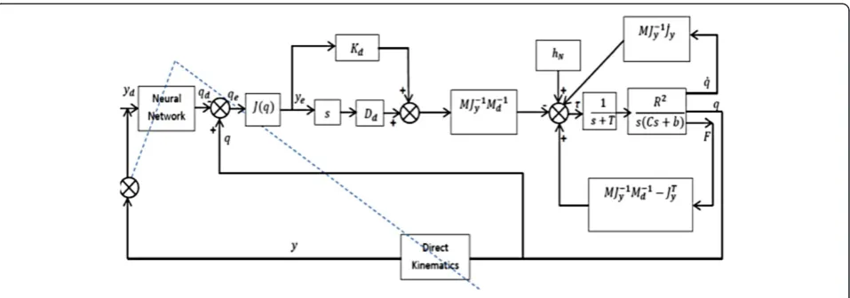
The control block diagram used for rehabilitation pur-pose shown in Figure 2.
Therefore, the necessary joint torques to obtain de-sired impedance parameters are computed as: (Eq. (3) is obtained from the dynamic equation of robot
manipulator that is in contact with its environments in joint space [2]):
τ¼hN q;q̇
−M qð ÞJ−y1ð ÞqJ̇yð Þq q̇−M qð ÞJ−y1ð Þq Md−1DdẏeþKdye þ M qð ÞJ−1
y ð ÞqM−d1−JTy
h i
F
ð3Þ
Where theyand subscriptydenote the task space and theqdenotes the joint space.
In this equationτ2*1is the torque input vector,qd2*1is the joint vector, y2*1 is the manipulator’s end effector vector, q2*1 is the joint angle vector, hN(q٫˙q)2*1 is the Coriolis and centrifugal force effects and other effects (such as gravity), M(q)2*2 is the inertia matrix, Md2*2 is the desired inertia matrix, J 2*2 is the Jacobean matrix, Dd2*2is the desired damping coefficient matrix,Kd2*2is the desired stiffness coefficient matrix andF2*1is exter-nal force exerted on the end-effector by its environment (this force can be defined as action and reaction force between patient and end-effector).
The term R2
s Csð þbÞ denotes the transfer function of any
arm of robot, equipped with a DC servo motor, where R is the gear reduction ratio in motor and the parameters C and b are the effective moment of inertia and viscous friction coefficient, respectively [15]. 1
sþT is the amount of approximated delay.
In the applied control structure, Neural Network box is used to convert yd (desired position) to qd (desired joint angles). And y is the target of NN. In this block diagram, it is assumed that:
ye¼dy¼J qð Þdq≅J qð Þqe ð4Þ
Whereγerepresents the error, or deflection of the MP (y) from its reference/desired position (yd) and qe
represents the error, or deflection of the joints (q) from its desired position (qd).
Patient safety in the proposed algorithm
Patient safety is one of the most important factors in re-habilitation systems and can be guaranteed by the stabil-ity of software and hardware. Stabilstabil-ity conditions for robotic systems under impedance or hybrid controllers had been investigated in some researches [1,8,17,19]. In this paper, a new asymptotic stability conditions for stiffness and impedance controllers is applied using an appropriate Routh approach [15] based on the rela-tionship between a joint angle of the robot and desired trajectory. Corresponding transfer function can be defined as:
G sð Þ ¼C sð Þ R sð Þ¼
q
qd ð5Þ
According to Eq. (3) and the following substitutions:
F¼K ye ð6Þ
Ф¼M qð ÞJ−1y ð Þq ð7Þ
hN q;q̇
¼Nq ð8Þ
Wheregis the gravitational acceleration,mis the mass of patient leg, Lg is distance between the joint and the mass center of link and N is the effects (Coriolis and centrifugal force effects and other effects such as gravity) without static (coulomb) friction (friction ignored).
The transfer function of Eq. (3) will be:
G sð Þ ¼C sð Þ R sð Þ¼
q qd
¼ ФM−1d DdJ
sþФM−1d KdJ−ФM−1d KJþJTKJ s2ðФJþRCÞ þs TRCþ1þФM−1
d DdJ
þ ФM−1d KdJ−ФM−1d KJþJTKJþNÞ
ð9Þ
The denominator polynomial is:
d sð Þ ¼s2ðФJþRCÞ
þs TRCþ1þФM−1d DdJ
þ ðФM−1d KdJ−ФM−1d KJþJTKJþNÞ
¼a0s2þa1sþa2 ð10Þ
After determining the stability conditions of controller gains based on Routh’s theory [15], and taking into ac-count that (M,K,D) are positive definite matrices, there will be:
RC>−ФJ ; ФMd−1KdJþJTKJþN
>ФM−1d ð11Þ
If we consider one of the joints of suggested robot (knee joint) and small movement these substitutions will be obtained:
M¼I; Jy¼JTy ¼Lg; J−1y ¼1 Lg
hn¼τgravity¼mgsin qð ÞLg ¼mgqLg
Dd;Kd¼I; Md¼ 1
2I; Lg ¼1m; g¼−10 m
s2 =
Now the transfer function of (5) will be:
G sð Þ ¼ −2sR
2þkR2−2R2
s3ð−CÞ þs2ð−TC−bÞ þs−bT−2R2þR2ð10m−2þkÞ
ð12Þ
The denominator polynomial is:
d sð Þ ¼s3ð−CÞ þs2ð−TC−bÞ þs−bT−2R2
þR2ð10m−2þkÞ
Then the stability condition will be:
k>2T R
2−10mT R2−ðTCþbÞ2R2þbT
T R2 ð13Þ
As shown in the next sections, the deviation of actual path from the desired path is considered as another system stability condition. In this paper, safety is guar-anteed since some of the controller parameters can be adapted under the following criteria:
1- The stability constraints in (11) or (13)
2- Desired deviation or difference between actual and desired path (ΔPdwill be explained in next section).
3- Different stroked patients (obtained from physiotherapist).
4- Different states of progression in the therapy process (by progress of rehabilitation steps and improvement in movement or feeling less pain obtained from physiotherapist).
5- The action/reaction force (F) between patient and robot (by a force sensor).
The robot is stopped when the safety factors is not sat-isfied. Thus, the recommended control strategy will be based on the combination of two strategies: impedance control and adaptive strategy. Controller parameters are finely tuned using a constrained non-linear optimization strategy such as GA that will be discussed in next section.
Optimization of control parameters
Strategies for solving old optimizing algorithm problems mostly depend on kind of aim, limit factors (linear, non-linear) and types of applied variation in sampling (true and natural). This is a fact that old optimizing ap-proaches, causes limitations in solving mathematical programming and applied research approaches and this is mainly because of intrinsic solving mechanism in those approaches. One of the main features of old opti-mizing algorithms is their inflexibility for the supposed problem and it’s adaptation to possible and dynamic changes. Optimization means the way that tries to find the best parameter values in a function and in this paper the minimal deviation between actual and desired path must be found. For this purpose the classic strategies of optimal control can be used and by getting transfer function, the optimal parameters ((Md٫Kd٫Dd)٫F) are found to minimize the following cost function:
Cost F¼∫n0e tð Þ2dt ð14Þ
Eq. (15) is used for calculation of deviation between actual and desired path [20].
ΔP¼CF ð15Þ
WhereCis the compliance matrix and it is defined as:
C¼JK−1JT ð16Þ
WhereKis the stiffness matrix andJ*is defined as:
J¼F−1TτT ð17Þ
Now the impedance control parameters are modified so that cost function (18) can be minimized:
Cost F¼‖ΔP‖ ð18Þ
In this case, because of the interaction between robot and human, the amplitude of force Fis very important and its high value can damage the patient. Therefore, the cost function is rewritten as:
Cost F¼minð‖ΔP‖Þ subject to ðF≤THRESHOLD Ftð ÞÞ
ð19Þ
The threshold of force is changed based on the ther-apy of different stages and patient qualification. We can incorporate constraint ofFin the cost function (19) and define a new cost function as:
Cost F¼αFþβj jΔP; ðαþβ¼h;h≥1Þ ð20Þ
Where α٫β٫hare changed based on the therapy of dif-ferent stages and patient improvement (adaptive strat-egy).hcan be called the accuracy factor as larger values of hwill result in higher accuracy. Now the control pa-rameters such as (Md٫Kd٫Dd) and evenFused for deter-mination of necessary torques of links based on Eq. (3) are optimized by using a genetic evolutionary algorithm that will be explained in the next section.
Genetic algorithm
GA is a multi-purpose search and optimization algo-rithm that is inspired by the theory of genetics and nat-ural selection. The problem to be solved using GA is encoded as a chromosome that consists of several genes. The solution of the problem is represented by a group of chromosomes referred to as a population. In each iter-ation of the algorithm, the chromosomes in the popula-tion will undergo one or more genetic operapopula-tions such as crossover and mutation. The result of the genetic op-erations will become the next genop-erations of the solu-tion. This process continues until either the solution is found or a certain termination condition is met. The idea behind GA is to have the chromosomes in the population to slowly converge to an optimal solution. At the same time, the algorithm is supposed to maintain
enough diversity so that it can scan a large search space. It is the combination of these two characteristics that makes GA a good search and optimization algorithm.
In the suggested algorithm value representation is used and the cost function is considered as Eq. (20). The main goal is to reach the minimum level of (ΔP) consid-ering (F) which will not be higher than the defined threshold. On the other hand, since the parameters are dimensional, chromosomes will be multi-dimensional instead of being a linear vector. In this case, Md٫Kd٫DdandFwill be the genes of each chromosome.
Thus, the chromosome length will be increased which in turn would result in the increase of problem complex-ity. For this reason, it is essential to find some tech-niques to decrease the chromosome length. Some of applicable techniques are:
Converting the population of chromosomes to multi population.
Fixing some of the parameters in any chromosome that are not very important or critical.
Assuming the parameters of any chromosome as diagonal matrix.
In the first technique, the optimization of the whole parameters will not be done simultaneously and prob-ably it will not result in the optimum result. The second technique is incoherence with the desired aim (adapting the controller parameters under the stability condition for different stroked patients and for different states of progression in the therapy process). Therefore, the third technique is applied in this study. And our mechanism for parent selection is truncation selection with this de-fined threshold in any generation.
T = average of Fitness_Function
Crossover operator is defined as one point crossover and point of crossover is selected randomly.
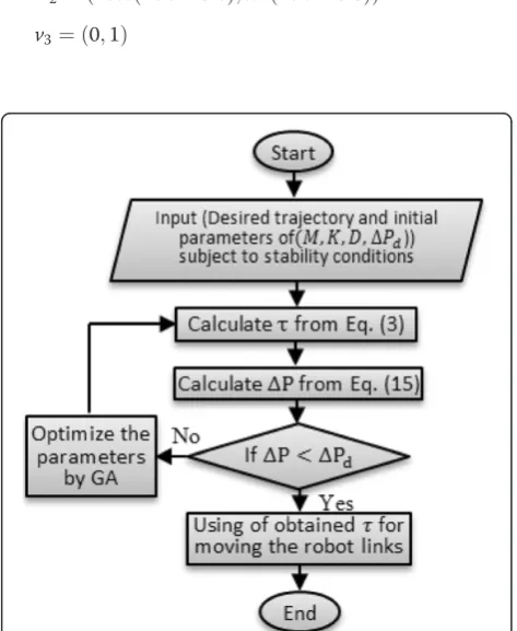
The flowchart of suggested algorithm is shown in Figure 3.
Results and discussion
For implementation of the suggested algorithm on the planar 2-DOF robot described in previous sections, there are several requirements (in terms of position, joint torques, impedance parameters) needed to control the manipulator (MP) as the sequel:
1- Desired position and velocity (trajectory) of MP and
ΔPdobtained from the physiotherapist.
2- Finding the appropriate joint variables with desired trajectory based on IK implemented by NN. 3- Optimization of impedance control parameters
All these requirements were discussed in the previous sections.
For this purpose, a physiotherapy simple mode and its trajectory are defined which are shown in Figure 4.
The angles and velocities of joints for this robot are planned in three phases:
1) Horizontal trajectory from (x٫0) to (xr٫0)with the speed of 1 m/s wherexis the leg length in
maximum extension andxris the distance between
hip source and manipulator in minimum flexion inx
direction (it is marked as the 1st phase in Figure4). 2) Circular trajectory around hip from (xr٫0)to (0٫yr)
with the speed of 1 rad/s whereyris the distance between source and manipulator in minimum flexion inydirection (it is marked as 2nd phase in Figure4).
3) Vertical trajectory from (0٫yr) to (0٫y) with speed of 1 m/s whereyis the leg length in maximum extension (in it is marked as 3rd phase in Figure4).
Assuming:
x¼1:86;y¼1:86;xr¼yr¼0:1
The velocities in three phases will be: v1¼ð−1;0Þ
v2¼ð−cosð10:t−18:6Þ;sinð10:t−18:6ÞÞ
v3¼ð0;1Þ
Angles of the joints in this physiotherapy mode are obtained based on the equations of the inverse kinematic (IK) problem in the suggested 2-DOF planar robot:
q2¼acos
x2þy2−l21−l22 2l1l2
ð21Þ
q1¼atan2 y
x −atan2
l2sinð Þq2 l1þl2cosð Þq2
ð22Þ
Taking into account the following:
x2þy2−l21−l22 2l1l2
≤1 ð23Þ
And they are shown in Figure 5. This figure depicts three phases in desired trajectory described in Figure 4.
Where the range of joint2 is complementary of q2 in Eq. (2).
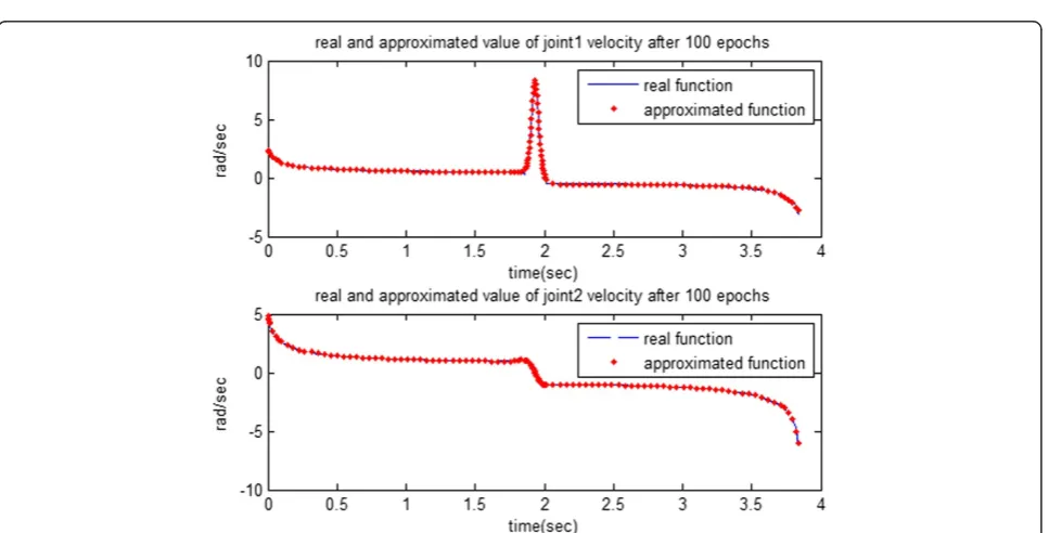
Now, the proposed MLP neural network is used for solving the IK problem. The weight and bias of the MLP neural network for joint1 approximation are obtained after training for 100 epochs which are shown in Table 1. In this table w{1,1} and bi{1} are the weights and biases of layer (1), respectively and w{2,1} and bi{2} are the weights and bias of layer (2), respectively.
The estimated values are shown in Figures 6 and 7, respectively.
The impedance parametersKd, Dd,Mdare initially se-lected by a trial and error method subject to stability conditions and then they are tuned using GA algorithm. These parameters are chosen as below:
Kd¼diag Ksð Þ;Dd¼diag Dsð Þ;Md¼diag Mdsð Þ
Figure 4Trajectory in three phases.
where the initial parameters are:
Ks¼0:05 N
m ;Ms¼0:05kg;Ds¼0:05 Ns
m
If we consider ΔPd= 10cm and the characteristics of robot links as:
l robot armsð Þ ¼1m;
m1¼0:7kg; m2¼0:5kg ðlink weightÞ
T¼0:01sec⋅⋅⋅⋅R¼0:001; C¼0:1; b¼400
The forces and torques that will be used for moving manipulator on the desired path (for 140 points of tra-jectory in 4 sec) are shown in Figures 8 and 9, respectively.
The evident peaks in Figure 9 denote the complemen-tary movement.
The final optimized control parameters based on re-lated torques and forces obtained as follows:
Ms¼51:2 N
m ;Mds¼4:882810
−5kg;Ds
¼0:05 Ns m
Now, the obtained torques from Figure 9 are used for moving the robot. Figures 10 and 11 show the actual (q) and desired joint angles. It should be noted that the de-sired joint angles were approximated by MLP neural net-work that have been already described.
According to Figures 10 and 11 the deviation or difference between desired and actual variables is large for the first
stages which are not suitable for rehabilitation without super-vision. The deviation becomes smaller and converges to zero with the progress of simulation steps.
The difference between the desired and actual trajec-tory is shown in Figure 12.
Figure 5Angles and velocities of joints.
Table 1 Weight and bias of proposed MLP neural network for joint1 approximation
w(1,1) w(2,1) bi(1) bi(2)
−1.3370 −2.7945 2.3883 0.4767
0.1686 −0.6542 −0.3739
0.1437 −0.3735 −0.1026
0.1332 −0.2878 −0.0565
0.1914 −0.8640 −0.6795
0.9674 2.5398 0.0812
1.1624 −0.6009 −1.2252
−0.1694 0.6654 0.3890
−0.1473 0.4066 0.1242
0.1583 −0.5220 −0.2194
3.0389 −1.9478 −5.9277
−0.0881 1.4560 −1.0628
−0.1891 0.8422 0.6456
0.1916 −0.8684 −0.6839
0.1392 −0.3344 −0.0800
0.1100 −0.1665 −0.0099
−0.1663 0.6228 0.3329
−1.0580 0.0915 1.6298
Finally, fitness function diagram of GA for Eq. (20) is displayed in Figure 13.
And the optimal values for GA parameters are obtained as:
α¼1:466⋅⋅⋅⋅;⋅⋅⋅⋅β⋅¼⋅2:006
As the Figure 13 shows, the best control parameters obtained after 100 generations and the fitness function value is: -15.287.
Conclusions
In this study, a therapeutic exercise planar 2-DOF robot was designed and controlled for lower-limb
Figure 6Approximated joint angles that produced from MLP network after 100 epochs.
rehabilitation. The robot manipulator was controlled by combination of hybrid and adaptive controls. Some safety factors and stability constraints were defined and obtained. The robot is stopped when the safety factors are not satisfied. Kinematics of robot is esti-mated by an MLP neural network and proper control parameters are achieved using GA optimization.
The advantages of the proposed algorithm can be clas-sified as the following:
1. The system is capable of learning the action of the physiotherapist for each patient and imitating this behavior in the absence of a physiotherapist that can be called robotherapy.
Figure 8Forces on manipulator.
Figure 9Torques on the joints.
Figure 10The actual and desired joint2.
2. Generation of the source path is completely deliberative and it is done in accordance with the patient’s condition and the therapy’s duration. In this research, the source path was specified after various efforts such as visiting the specialists of the
physiotherapy and observing several sessions in that section to completely gather the whole required information.
3. The neural network identifiers were used for solving the inverse kinematic of robot. The first idea for
using NN is to cope with a non-linear identification problem and the second, more important one, is that the patient’s joints controlling system can be probably replaced by the artificial neural network. 4. Safety is guaranteed since some of the controller
parameters can be adapted under the stability condition for different stroked patients and for different states of progression in the therapy process. 5. To reduce the complexity of optimization of control
parameters, genetic evolution method was used. A different aspect of the defined chromosomes in the suggested algorithm in comparison to conventional methods is that they are defined as matrices not as vectors which were placed because of the abundance of DOF for a system.
In comparison to other related works, some other re-markable issues can be added as follows:
6. The work places that are needed for LOKOMAT [5] and LOPES [7] must be in a large room while the whole place that is needed for manufactured robot is 1 m2 in maximum. Moreover, the cost of rehabilitation with LOKOMAT is very high. 7. The number of DOF in ALEX [6] is very high but in
2-DOF planar robot it is limited to 2.
8. Only two parameters regarding the patient are used for starting the rehabilitation including mass of patient and ability in posture of ankle on the MP. The other parameters such as patient muscles, length and posture of whole body are not required.
Figure 12Difference between desired and actual trajectory.
Abbreviations
CPM:Continues passive motions; GA: Genetic algorithm; MLP: Multi layer perceptron; MP: Manipulator; IK: Inverse kinematic.
Competing interests
The authors declare that they have no competing interests.
Authors’contributions
FN proposed the design. WAA implemented the design on a manufactured 2–DOF robot. MAN worked on the optimization. All authors read and approved the final manuscript.
Authors’information
Wahab Amini Azar, received his B.Sc. in 1999 in Computer Engineering from the Shahid Beheshti University, Tehran, Iran and his M.Sc. in 2002 in Computer Engineering from the Amir Kabir University, Tehran, Iran. And currently he is Ph.D. student at Islamic Azad University, sciences and research branch,Tehran, Iran. Farid Najafi, received his B.Sc. in Mechanical Engineering From Department of Mechanical Engineering, Sharif University of
Technology, Iran, and his M.Sc. and Ph.D. degrees From Faculty of Robotics and Automation, Moscow State Technical University (Bauman), Russia (in 2006). Now, he is associate professor of mechanical engineering at Guilan University, Rasht, Iran and working in the field of automatic control, robotics and mechatronic systems. Mohammad Ali Nekoui received his M.Sc. degree in Electrical Engineering from the University of Tehran in 1976, Diplome d’Espe cialisation in Instrume-ntation etMetrologie from Ecole Superieur d’Electricite (SUPEL EC), France, in 1979 and his Ph.D. degree at the School of Electrical and Electronic Engineering in Computer and Control Department from University of Leeds, U.K. in 1997. Since 1980, he has been with the K.N. Toosi. University of Technology. At present he is an Assistant Professor at the Faculty of Electrical and Computer Engineering of this university. His interests include linear and nonlinear optimization, linear systems, optimal control, and different aspects of mathematics in control.
Acknowledgements
This project was partly supported by mechatronic Lab of Islamic Azad University and currently some of handicapped patients are under therapy by this method. A 2-DOF robot manufactured by IAU robotic team for this purpose.
Author details 1
Department of Electrical Engineering, Science and Research branch, Islamic Azad University, Tehran, Iran.2Department of Mechanical Engineering, Engineering Faculty, Guilan University, Rasht, Iran.3Department of Electrical Engineering, K.N.Toosi. University of Technology, Tehran, Iran.
Received: 25 September 2012 Accepted: 26 July 2013 Published: 14 August 2013
References
1. Tsoi YH, Xie SQ:Impedance Control of Ankle Rehabilitation Robot, In proceedings of the IEEE International Conference on Robotics and Biomimetics. Bnagkok ROBIO; 2008:840–845.
2. Erhan AG, Ertu˘GT, AA M:Knee rehabilitation using an intelligent robotic system.Intell Manuf2009,20:195–202.
3. Neptune RR, Kautz SA, Zajac FE:Contributions of the individual ankle plantar flexors to support forward progression and swing initiation during walking.J Biomech2001,34(11):1387–1398.
4. Palmer LR:Sagittal plane characterization of normal human ankle function across a range of walking gait speeds.Department of Mechanical Engineering, MIT: Master’s thesis; 2002.
5. Lünenburger L, Colombo G, Riener R, Volker D:Clinical Assessments Performed during Robotic Rehabilitation by the Gait Training Robot Lokomat, Proc. Of the IEEE 9th International Conference on Rehabilitation Robotics: 28 June - 1 July 2005. Chicago, IL, USA; 2005:345–348.
6. Banala S, Agrawal S, Scholz J:Active Link Exoskeleton (ALEX) for Gait Rehabilitation of Motor-Impaired Patients, Proc. of the IEEE 10th International Conference on Rehabilitation Robotics: 12-15 June 2007. Noordwijk, The Netherlands; 2007:401–407.
7. Veneman J, Kruidhof R, Hekman E, Ekkelenkamp R, Van Asseldonk E, Van Der Kooij H:Design and evaluation of the LOPES exoskeleton robot for
interactive gait rehabilitation.IEEE Trans Neural Syst Rehabil Eng2007, 15:379–386.
8. Erhan AG, Mehmet AA:The design and control of a therapeutic exercise robot for lower limb rehabilitation.Physiotherabot. Mechatronics2011, 21:509–522.
9. Fuchun S, Zengqi S, Nan L, Lingbo Z:Stable adaptive control for robot trajectory tracking using dynamic neural networks.Machine Intelligence & Robotic Control1999,1:71–78.
10. Robert R, Member IEEE, Lars L, Member IEEE, Saˇso J, Associate Member IEEE, Martin A, Gery C, Volker D:Patient-cooperative strategies for robot-aided treadmill training: first experimental results.IEEE Truncations on neural systems and rehabilitation engineering2005,13:3.
11. Emken J, Bobrow J, Reinkensmeyer D:Robotic Movement Training s an Optimization Problem: Designing a Controller that Assists Only as Needed, Proc. of the IEEE 9th International Conference on Rehabilitation Robotics: 28 June - 1 July 2005. Chicago, IL, USA; 2005:307–312.
12. Jiménez F, Verlinden O:Review of control algorithms for robotic ankle systems in lower-limb orthoses, prostheses, and exoskeletons.Service de Mécanique Rationnelle, Dynamique et Vibrations.Belgium: Faculté Polytechnique, Université de Mons. doi:10.1016/j.medengphy.2011.11.018. 13. Schmidt H, Werner C, Bernhardt R, Hesse S, Krüger J:Gait rehabilitation
machines based on programmable footplates.J Neuroeng Rehabil2007,4:2. 14. Huang V, Krakauer J:Robotic neuro rehabilitation: a computational motor
learning perspective.Journal of Neuro Engineering and Rehabilitation2009,6:5. 15. Ogata K:“Modern control engineering.N.J: Prentice-Hall of Englewood Cliffs; 1970. 16. Yoshikawa T:Foundations of robotics: analysis and control.Cambridge:
MIT Press; 1990.
17. Hogan N:Impedance control: an approach to manipulators. Part 1, 2, 3. J Dyn Syst Meas Control1985,107(1):24. doi:10.1115/1.3140702.
18. Natasa K, Saso K, Pierluigi Beomonte Z, Francesco D:Control Architecture for a Lower Limbs Rehabilitation Robot System.Bangkok, Thailand: Proceedings of the IEEE International Conference on Robotics and Biomimetics; 2009:21–26.
19. Hogan N:Impedance control of industrial robots.Robot“Comput-Integr Manuf1984,1(97):113. doi:10.1016/0736-5845(84)90084-X.
20. Robert JS:fundamentals of robotics, analyze and control.India: prentice hall of India New Delhi press; 2003.
doi:10.1186/1743-0003-10-96
Cite this article as:Aminiazaret al.:Optimized intelligent control of a 2-degree of freedom robot for rehabilitation of lower limbs using neural
network and genetic algorithm.Journal of NeuroEngineering and
Rehabilitation201310:96.
Submit your next manuscript to BioMed Central and take full advantage of:
• Convenient online submission
• Thorough peer review
• No space constraints or color figure charges
• Immediate publication on acceptance
• Inclusion in PubMed, CAS, Scopus and Google Scholar
• Research which is freely available for redistribution